is an open access repository that collects the work of Arts et Métiers Institute of Technology researchers and makes it freely available over the web where possible.
This is an author-deposited version published in: https://sam.ensam.eu Handle ID: .http://hdl.handle.net/10985/7460
To cite this version :
Patrick CHERDIEU, Antoine DAZIN, Patrick DUPONT, Annie-Claude BAYEUL-LAINE, Olivier ROUSSETTE, Gérard BOIS - Analysis of Unsteadinesses in a Vaned Diffuser of Centrifugal Machinery. - In: Congrès français de mécanique (21 ; 2013 ; Bordeaux (Gironde))., France, 2013-08-26 - Congrès français de mécanique (21 ; 2013 ; Bordeaux (Gironde)). - 2013
Analysis of Unsteadinesses in a Vaned Diffuser of
Centrifugal Machinery
P. Cherdieua, A. Dazinb, P. Duponta, A.C. Bayeul-Lainéb, O. Roussetteb, G. Boisb
a. Ecole Centrale de Lille, LML, UMR CNRS 8107, Bd Paul Langevin, 59655 VILLEUNEUVE D’ACSQ
b. Arts et Métiers PARISTECH, LML, UMR CNRS 8107, Bd Paul Langevin, 59655 VILLEUNEUVE D’ACSQ
Résumé :
L’objet de cet article est de présenter des résultats expérimentaux obtenus sur un ventilateur constitué d’une roue radiale suivie d’un diffuseur aubé. Il n’y a pas de volute à l’aval du diffuseur de telle sorte que l’écoulement refoule à l’air libre. Une particularité de cette machine est que le débit nominal du diffuseur correspond à 80% du débit nominal de la roue. Des investigations ont été faites pour cinq débits différents. Les performances globales de la machine sont évaluées grâce à des mesures de pression et de vitesse moyennes obtenues avec une sonde 3 trous, à 9 positions angulaires en entrée et en sortie du diffuseur ainsi que 5 positions radiales au niveau d’une section moyenne d’un canal interaubes. Afin de mieux caractériser les décollements observés lors d’études expérimentales et numériques précédentes, des campagnes de mesures de pressions instationnaires ont été réalisées. Les capteurs sont localisés à cinq positions sur la face en pression et quatre positions sur la face en dépression des aubes du diffuseur dans un plan aube à aube. Pour chaque position, trois capteurs sont placés à trois hauteurs différentes, du moyeu au carter. Les instationnarités mises en évidence par ces mesures ainsi que leurs effets sur la performance du diffuseur sont analysés.
Abstract :
The aim of this article is to present experimental results obtained on a fan composed of a radial im-peller matched with a vaned diffuser. There is no volute downstream to the diffuser. Consequently the diffuser outlet is at free air. The particularity of this machinery is that the diffuser design flow rate corresponds to 80% of the impeller one. Investigations have been made for five different flow rates. Global performances of the machine are evaluated thanks to pressure measurements and averaged ve-locities obtain with a three holes probe, at nine angular positions at diffuser inlet and outlet just as five radial positions in a middle section of a blade-to-blade passage. In order to better characterize separations observed in previous experimental and numerical studies unsteady pressure measurement campaigns have been carried out. The transducers are located at five positions on the pressure face and four positions on the suction face on diffuser vanes in a blade-to-blade plane. For each position, three transducers are located at three different heights, from hub to shroud. Unsteadinesses revealed by these measurements just as theirs effects on the diffuser performance are analysed.
Mots clefs :
centrifugal fan ; PIV; unsteady pressure measurements; vaned diffuser1
Introduction
In centrifugal pumps and fans the flow is complex (three dimensional and unsteady) and combine several features; in the diffuser of such machines the main source of unsteadiness is the interaction of rotating blades of the impeller with the diffuser vanes [1, 7, 8, 9]. These unsteadinesses increase when the machine is not operating at its design flow rate. To study these unsteady flows, previous works
involving PIV measurements had been conducted on the so-called SHF impeller [4, 11]. They revealed the occurrence of fluctuating separation regions on the vanes at off-design conditions. The aim of the present paper is to enrich previous studies by analyzing the diffuser performance and exploring the effects of these separation regions on the pressure fluctuations in the diffuser. To do so, new experimental campaigns have been conducted and are reported in this paper: they consisted in static pressure measurements on the diffuser walls, three-hole probe measurements and unsteady pressure measurements on the diffuser vanes. These experiments have been realized at five flow rates.
2
Experimental setup
The experiments have been conducted on a pump working with air and in similarity conditions com-pared to water. It is composed of the SHF impeller matched with a vaned diffuser whose characteristics are reported in table 1 and table 2.
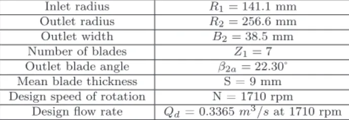
Inlet radius R1= 141.1 mm
Outlet radius R2= 256.6 mm
Outlet width B2= 38.5 mm
Number of blades Z1= 7
Outlet blade angle β2a= 22.30˚
Mean blade thickness S = 9 mm Design speed of rotation N = 1710 rpm
Design flow rate Qd= 0.3365 m3/s at 1710 rpm
Table 1: Impeller characteristics
Inlet radius R2= 273.6 mm
Relative radial gap (R3− R2)/R2= 6.65%
Outlet radius R4= 397.8 mm
Number of blades Z2= 8
Inlet blade angle α31= 10.21˚ (at the blade leading edge, R = 275.94 mm)
α32= 15.85˚ (in the center of the inlet throat, R = 298.06 mm)
Outlet blade angle α4= 39.55˚ (in the center of the inlet throat, R = 371.88 mm)
Constant width B4= 40 mm
Design flow rate 0.80 Qd
Table 2: Diffuser characteristics It has to be noticed that :
• there is no volute downstream to the diffuser in order to focus the analysis on the impeller-diffuser interaction.
• the diffuser design flow rate is corresponding to 80 % of the impeller design flow rate. This configu-ration has been chosen to obtain a better performance of the pump at partial flow rates.
A more detailed presentation of the test rig is proposed in [2, 3, 4, 6] and a sketch in figure 2. Several types of measurements have been carried out in the diffuser :
• The performance and the pressure rise of the diffuser were estimated by :
- static pressure measurements on the shroud wall of the diffuser (figure 1(a)) with a YEW Type 2654 digital manometer associated with a 20 pneumatic lines BEXHILL selector.
- three-hole probe measurements (figure 1(b)) which holes are connected to a Honeywell type pres-sure tap device.
• Besides, unsteady pressure measurements were obtained with 8510B-1 Endevco pressure transducers (figure 1(c)) on the suction and pressure sides walls of two diffuser vanes in the same passage. The unsteady pressure measurements were held with an acquisition time of 300 s and a sampling frequency of 6000 Hz. To avoid aliasing, a low pass filter was used with a 3000 Hz cut-off frequency. Auto Power Spectrum was realized with 2048 points Hanning windows with 50% overlap.
For all campaigns, the impeller rotation speed was 1710 rpm, for five flow rates (Q/Qd=0.38, 0.59,
(h = 20mm). The results of these campaigns are compared to already published [4, 6, 11] 2D-2C Particle Image Velocimetry (PIV) data which were obtained for four flow rates. The image acquisitions were phase locked with the impeller position for 7 impeller positions.
(a) Static pressure locations (b) Three-hole probe locations (c) Pressure transducers locations
Figure 1: Experimental campaigns
3
Global peformance
Figure 2: Sketch of the test rig Figure 3: Global performance, Ψ = ∆P ρ ∗ U2
2
, ∆P :static pres-sure rise, ρ:air density and U2:rotational velocity at impeller
outlet
Figure 3 shows the performance of the fan and its components. What is obvious in this figure is that the diffuser performance is very bad for Q > Qd, as the static pressure is decreasing which means there
are great losses in it. A more detailed analysis of the diffuser performance is proposed in figure 4 which presents the static pressure evolution with radius. The analysis of this figure shows clearly that the diffuser can be divided in two regions :
– the first one, for r*<0.2, corresponds to a region located between the diffuser inlet and the diffuser inlet throat. In this region the static pressure rise for Q/Qd=0.385, 0.579 and 0.762, whereas the
static pressure decreases for Q/Qd=0.975 and 1.134. Concerning this region, it is also noticeable
that the pressure recovery is not so good at Q/Qd=0.762 whereas this flow rate is the closest to the
diffuser design flow rate. This could be explained by the existence of a "positive" leakage (that is, from the ambient air to the machine) flow in the gap between the diffuser and the impeller which implies that the real diffuser mass flow rate is greater than the impeller mass flow rate. This is confirmed by the existence of a small detached region near the vane leading edge at this flow rate, as it was evidenced by [5] and [11].
– the second one, for r*>0.2, corresponds to a region downstream to the diffuser inlet throat. In this region the static pressure rises with radius whatever the flow rate is and the pressure rise increases with the flow rate.
The bad performance of the diffuser at high flow rates observed figure 3 (a) can be linked to losses in the first region of the diffuser. The rest of the paper will focus on the flow behavior in this region.
Figure 4: Static pressure evolution in the diffuser, ΨD = P − P3
ρ ∗ U2 2
, P: local static pressure, P3: static
pressure at diffuser inlet, ρ: air density, U2: rotational velocity at impeller outlet and r∗ = R − R3
R4− R3
4
Analysis and results
(a) Q/Qd= 0.588, θ = −0.89˚ (b) Q/Qd= 0.588, θ = 5.29˚ (c) Q/Qd= 0.588, θ = 20.75˚ (d) Q/Qd= 0.934, θ = −0.89˚ (e) Q/Qd= 0.934, θ = 5.29˚ (f) Q/Qd= 0.934, θ = 20.75˚ (g)
Figure 5: Turbulence rate, θ : angular relative position between the impeller blades and diffuser vanes. This paragraph will focus in the first region of the diffuser to try to identify the flow phenomena associated with the losses evidenced at the two greater flow rates. It will be illustrated by comparing results obtained at Q/Qd = 0.57 where a strong pressure rise was observed and Q/Qd= 0.934 where
an important pressure decrease was noticed. Figure 5 presents turbulent rate charts obtained, from PIV results, for two flow rates and for several position of the impeller. In these charts, there are red zones of high turbulence (>10%). In the impeller, theses areas should not be considered for the analysis of the results because they are representative of inconsistent values [11]. At the lower flow
Impeller blade
Diffuser vane Diffuser vane
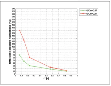
Figure 6: RMS Pressure
rate (Q/Qd = 0.57), the turbulent rate is moderate (<5%) in the whole domain whereas a region of
high turbulence is existing at the greater flow rate. This region is the evidence of a separation of the boundary layer. It has also to be noticed that the size of this zone is fluctuating with the impeller position: it is greater when the impeller is facing the diffuser vane leading edge.
The effect of this separation is directly noticeable on the pressure fluctuations measured on the diffuser vanes on the pressure side (figure 6): it can be seen, for (Q/Qd = 0.57), that the level of fluctuation
is moderate (lower than 70 Pa) and decreasing with radius to reach 10 Pa at diffuser outlet. On the contrary, at Q/Qd = 0.934, the RMS pressure fluctuations are reaching 160 Pa at the vane leading
edge and stays at a high level while r*<0.2 which corresponds more or less to the separated region. On the contrary, for normalized radii greater than 0.3 (that is outside of the separated region) the level of the RMS fluctuations is becoming close to the values measured at Q/Qd= 0.57.
The high values of the RMS observed at Q/Qd= 0.934 can be attributed to two different factors, as
it can be deduced from the analysis of the spectra presented in figure 7.
– First of all, there is an increase of the peak associated with the blade passing frequency (BPF) and its harmonics which could be related to the pulsations of the separated regions evidenced on the charts.
– Secondly, there is a global increase of the amplitude on a large band of frequency which could be associated with the increase of the turbulent rate [10].
On the contrary, outside from the separated region, the spectra obtained at Q/Qd= 0.57 and Q/Qd=
0.934 are very similar (fig 6b).
(a) (b)
5
Conclusions
Some experiments including PIV and static pressure measurements managed in the vaned diffuser of a centrifugal fan were reported in the present paper. They have evidenced the occurrence of a large fluctuating separated region at the leading edge of the diffuser, on pressure side. This region induces an increase of the peak associated with the BPF and its harmonics as well as a global increase of the pressure amplitude on a large band of frequency. Consequently, the RMS value of fluctuations is also increased. The presence of this phenomenon affects badly the performance of the diffuser as it is increasing highly the losses in the region between the vane leading edge and the inlet throat of the diffuser.
Acknowlegments
The authors wish to thank CNRS, the Région Nord-Pas-De-Calais and CISIT Consortium for their financial support.
References
[1] Arndt, N., Acosta A.J., Brennen C.E., Caughey T.K. 1990 Experimental Investigation of Rotor-Stator Interaction in a Centrifugal Pump With Several Vaned Diffusers ASME Journal of Turboma-chinery 112 98-108
[2] Atif, A.,Cherdieu, P., Bois, G., Terki Hassaine, T.E., 2012 Numerical and Experimental Com-parison of the Pressure Recovery Inside a Vaned Diffuser of a Centrifugal Pump and Performance Assesement Séminaire sur l’ ´Energie, Alger, 25-27 mars 2012
[3] Bayeul-Lainé, A.C.,Dupont, P., Cherdieu, P., Dazin, A., Bois, G., Roussette O. 2012 Comparisons between numerical calculations and measurements in the vaned diffusor of SHF impeller ISFMFE 2012, 5th International Symposium on Fluid Machinery and Fluid Engineering, 24-27 October 2012, Lotte Hotel, Jeju, Korea
[4] Cavazzini, G. 2006 Experimental and numerical investigation of the rotor-stator interaction in a radial turbomachines PhD Thesis, University of Padova, Padova, Italy, 2006
[5] Cavazzini, G., Pavesi, G., Ardizzon, G., Dupont, P., Coudert S., Caignaert G., Bois, G. 2009 Analysis of the rotor-stator interaction in a radial flow pump Houille Blanche-revue internationale de l’eau, 2009
[6] Cavazzini, G., Dupont, P., Pavesi, G., Dazin, A., Bois, G., Atif, A., Cherdieu, P. 2011 Analysis of unsteady flow velocity fields inside the impeller of a radial flow pump : PIV measurements and numerical calculation comparisons Proc. of ASME-JSME-HSME Joint fluids engineering conference 2011, July 24-29, 2011, Hamamatsu Japan
[7] Dawes, W.N. 1995 A simulation of the Unsteady Interaction of a Centrifugal Impeller With Its Vaned Diffuser: Flow Analysis Journal of Turbomachinery 117 213-222
[8] Feng, J., Benra, F.-K., Dohmen H.J. 2007 Numerical Investigation on Pressure Fluctuations for Different Configurations of Vaned Diffuser Pumps International Journal of Rotating Machinery 2007 10 pages
[9] Furukawa, A., Takahara, H., Nakagawa, T., Ono Y. 2003 Pressure Fluctuation in a Vaned Diffuser Downstream from a Centrifugal Pump Impeller International Journal of Rotating Machinery 9 285-292
[10] Simpson, R.L. 1996 Aspects of Turbulent Boundary-Layer Separation Progess in Aerospace Sci-ences 32 457-521
[11] Wuibaut, G. 2001 Etude par vélocimétrie par images de particules des interactions roue-diffuseur dans une pompe centrifuge. PhD Thesis, Thèse de Doctorat Ensam, 2001