HAL Id: hal-02882988
https://hal-insa-rennes.archives-ouvertes.fr/hal-02882988
Submitted on 8 Nov 2020
HAL is a multi-disciplinary open access
archive for the deposit and dissemination of
sci-entific research documents, whether they are
pub-lished or not. The documents may come from
teaching and research institutions in France or
abroad, or from public or private research centers.
L’archive ouverte pluridisciplinaire HAL, est
destinée au dépôt et à la diffusion de documents
scientifiques de niveau recherche, publiés ou non,
émanant des établissements d’enseignement et de
recherche français ou étrangers, des laboratoires
publics ou privés.
Shaking Force Balancing of the Orthoglide
Jing Geng, Vigen Arakelian, Damien Chablat
To cite this version:
Jing Geng, Vigen Arakelian, Damien Chablat. Shaking Force Balancing of the Orthoglide. In:
Zeghloul S., Laribi M., Sandoval Arevalo J. (eds) Advances in Service and Industrial Robotics. RAAD
2020. Mechanisms and Machine Science, vol 84. Springer, pp.227-234, 2020, 2211-0984.
�10.1007/978-3-030-48989-2_25�. �hal-02882988�
Jing Geng1,2, Vigen Arakelian1,2, Damien Chablat1 1
LS2N-ECN UMR 6004, 1 rue de la Noë, BP 92101, F-44321 Nantes, France
2
INSA Rennes / Mecaproce 20 av. des Buttes de Coesmes, CS 70839,
F-35708 Rennes, France [email protected]
Abstract. The shaking force balancing is a well-known problem in the
de-sign of high-speed robotic systems because the variable dynamic loads cause noises, wear and fatigue of mechanical structures. Different solutions, for full or partial shaking force balancing, via internal mass redistribution or by adding auxiliary links were developed. The paper deals with the shaking force balanc-ing of the Orthoglide. The suggested solution based on the optimal acceleration control of the manipulator’s common center of mass allows a significant reduc-tion of the shaking force. Compared with the balancing method via adding counterweights or auxiliary substructures, the proposed method can avoid some drawbacks: the increase of the total mass, the overall size and the complexity of the mechanism, which become especially challenging for special parallel ma-nipulators. Using the proposed motion control method, the maximal value of the total mass center acceleration is reduced, as a consequence, the shaking force of the manipulator decreases. The efficiency of the suggested method via numeri-cal simulations carried out with ADAMS is demonstrated.
Keywords: Shaking Force, Inertia Force Balancing, Spatial Parallel
Manipula-tors, Common Center of Mass, Optimal Control, Orthoglide.
1
Introduction
It is known that a mechanical system with unbalance shaking force/moment transmits substantial vibration to the frame. Thus, a primary objective of the balancing is to cancel or reduce the variable dynamic loads transmitted to the frame and surrounding structures.
The methods of shaking force balancing can be arranged as follows: i) by adding counterweight in order to keep the total mass center of moving links stationary [1-2]. It is obvious that the adding of the counterweights is not desirable because it leads to the increase of the total mass, of the overall size and of the efforts in joints; ii) by adding auxiliary structures. In [3-5], the parallelograms were used as auxiliary struc-tures in order to create the balanced manipulators. In [6], the pantograph has been
2
added in order to balance the shaking force of Delta robot; iii) by installing elastic components [7], [Erreur ! Source du renvoi introuvable.]; iv) by adjustment of kinematic parameters [Erreur ! Source du renvoi introuvable.], [Erreur ! Source du renvoi introuvable.]; v) via center of mass acceleration control [Erreur ! Source du renvoi introuvable.-Erreur ! Source du renvoi introuvable.].
The paper deals with the shaking force balancing of the Orthoglie [Erreur ! Source du renvoi introuvable.], [Erreur ! Source du renvoi introuvable.]. The Orthoglide is a three-degrees-of-freedom parallel manipulator with regular workspace and good compactness. Its three actuators are arranged according to the Cartesian coordinate space (Fig. 1). The moving platform is connected with actuators via three identical kinematical chains. In the paper, it is proposed to apply the shaking balanc-ing via the center of mass acceleration control.
2
Shaking force Balancing of the Orthoglide
2.1 Problem Formulation
Let us consider the kinematic architecture of the Orthoglide (Fig. 1). It consists of three identical kinematic chains that are formally described asPRP Ra , where P ,
Rand Padenote the actuated prismatic, revolute, and parallelogram joints respective-ly. The mechanism input is made up by three actuated orthogonal prismatic joints. The output body is connected to the prismatic joint through a set of three kinematic chains. Inside each chain, one parallelogram is used and oriented in a manner that the output body is restricted to translational movements only. The three parallelograms have the same lengthsLB Ci i. The arrangement of the joints in the PRP Ra chains has been defined to eliminate any constraint singularity in the Cartesian workspace. Each frame pointAiis fixed on the ith linear axis so thatA A1 2A A1 3A A2 3. The pointsBi andCiare located on theith parallelogram, as is shown in Fig. 1. The refer-ence frame is located at the intersection of the prismatic joint axes and aligns the co-ordinate axis with them. The details of the design of the Orthoglide and its optimiza-tion can be found in [16-18].
For the Orthoglide geometrical model (see Fig. 2), the inverse kinematic equations [18] can be drives in a straightforward way as:
2 2 2 x px sx L py pz
(1) 2 2 2 y py sy L px pz
(2) 2 2 2 z pz sz L px py
(3)where sx, sy, sz are the configuration indices that are equal to 1 ; The input vector of the three prismatic joints variables as ρ ( ,
x y, z) and the output position vec-tor of the tool center point asp(p px, y,pz). For the Orthoglide robot, a single in-verse kinematic solution is reachable. The shaking forces Fshof mechanisms can be written in the form:sh m && F s (4) where 1 n i i m m
is the total mass of the moving links of the manipulator and &s is the & acceleration of the total mass centre. As mentioned above, the shaking force balanc-ing via mass redistribution consists in addbalanc-ing counterweights [19] in order to keep the total mass centre of moving links stationary. In this case, &s&0 for any configuration of the manipulator and, as a result, the shaking force is cancelled. It is obvious that the adding of supplementary masses as counterweights is not desirable because it leads to the increase of the total mass, of the overall size of the manipulator, the efforts in joints, the shaking moment and the input torques. Therefore, in the present study, it is proposed to minimize the shaking force via reduction of the total mass centre accel-eration: ( ) max min s t &s& (5)i.e. to apply an optimal control of the total mass centre of moving links that allows one to reduce the maximal value of its acceleration.
For this purpose, let's consider the control of the spatial parallel manipulator Or-thoglide through of its centre of mass. To ensure it, let us assume that the centre of mass moves along a straight line between its initial and final positions. Thus, the mo-tion profile used on this path will define the values of shaking forces. For the same displacement of the total centre of mass Sand the displacement time t , the maximal value of the acceleration changes following the e motion profile [20]: For quantic polynomial profile, the amax 10S 3t2 ; For bang-bang profile, 2
max 4
a S t . It means the application of bang-bang law theoretically brings about a reduction of 31% of the maximal value of the acceleration. Hence, to minimize the maximum value of the acceleration of the total mass centre and, as a result, shaking forces, the “bang-bang” profile should be used. Thus, by reducing the acceleration of the centre of mass of the Orthoglide, a decrease in its shaking forces is achieved. Thus, to achieve the
4
shaking force balancing through the above described approach, it is necessary to con-sider the relationship between the input parameters and the centre of mass positions of the Orthoglide.
2.2 The relationship between the total centre of mass and the input parameters
In order to control the manipulator according to the method described above, it is necessary to establish the relationship between the displacement of the total centre of mass and the input parametersρ(
x, y, z), i.e. for the given position and the law of motion of the Common Centre of Mass (COM) of the manipulator determine its input displacements. Then, by means of the obtained input parameters via forward kinematics determine the position of the output axisP(p px, y,pz). For this purpose, itis necessary to establish the relationship between the common center of mass of the manipulator and its input parameters.
Let us start this issue with the initial and final positions P(p px, y,pz)of the plat-form Pi( ,x y zi i, i) and Pf(xf,yf,zf). So, by invers kinematics [18], the input an-gles corresponding to these positions will be determined: ρi(
xi, yi, zi) and( xf, yf, zf) f
ρ . The corresponding values of the common COM of the manipulator can also be found: SCOM_i(xSi,ySi,zSi) and SCOM_f (xSf, ySf,zSf). The
displace-ment of the total centre of mass is D(d d dx, y, z). Subsequently, a straight line con-necting the initial and final positions of the comment centre mass of the manipulator can be established and its trajectory planning by “bang-bang” profile with the time interval t can be ensured: f SCOMS
t , i.e.2 2 2 , (0 ) 2 ( ) 1 4 2 , (0 ) 2 f f f f f t t t t t t t t t t t COM_i COM_i S D S S D (6)
Let us now consider the relationship between SCOM
x t y t z t( ), ( ), ( )
and the inputdisplacementρ( x, y, z).
The common COM of the manipulator can be expressed as:
1 n i i m M
i COM r S (7)where i is the number of the moving link (i=1,…,n), SCOM is the coordinate vector of the total mass centre of the manipulator, riis the the coordinate vector of the linkagei, miis the mass of the linkagei.
where A is not on the three axis but has an offset namedl . At the same time,
1 2 3
C C C P. Thus, the coordinates of the joints along X, Y and Z axes are the followings:
X-axis: C1 (p px, y,pz); B1(x,0,0); A1(xl, 0, )l .
Y-axis: C2 (p px, y,pz); B2 (0,y, 0); A2 ( ,l yl, 0). Z-axis: C3 (p px, y,pz); B3(0,0,z); A3(0, ,l zl).
The mass centers of the parallelograms can be written as:
/ 2,
/ 2,
/ 2i i i i i i
C B C B C B
x x y y z z
, and their mass are m1. The mass
cen-ter of the three input links are:
/ 2,
/ 2,
/ 0i i i i i i
A B A B A B
x x y y z z
, the
masses of input links are denoted asm2. The coordinates of the mass center of the end-effector P arep px, y,pz and their masses are m3.
With the masses of the corresponding links, the expressions of the total center of mass of the moving links of the Orthoglide can be expressed as:
1 2 3 1 2 3 1 2 3 3 / 2 ( ) 3 / 2 ( ) 3 / 2 ( ) x x x x x y y y y y z z z z z S m p m l m p M S m p m l m p M S m p m l m p M (8)where,M3(m1m2)m3is the total mass of the moving links.
According to the proposed method, the displacement of the total center of mass should follow Bang-bang motion profile ( )S t , i.e.
2 2 2 , (0 ) 2 ( ) 1 4 2 , (0 ) 2 f Si x f f Si x f f t t x d t t x t t t t x d t t t (9) 2 2 2 () , (0 ) 2 ( ) 1 4 2 , (0 ) 2 f Si y f f Si y f f t t y d t t y t t t t y d t t t (10)
6 2 2 2 , (0 ) 2 ( ) 1 4 2 , (0 ) 2 f Si z f f Si z f f t t z d t t z t t t t z d t t t (11)
For each step of the movement, we finally obtain a group of three nonlinear Eq. (12) with 3 unknownspx, p andy pz:
2 2 2 1 2 1 2 3 2 2 2 2 1 2 1 2 3 2 2 2 2 1 2 1 2 3 2 ( ( / 2 ) (2 ) ) / ( ) ( ( / 2 ) (2 ) ) / ( ) ( ( / 2 ) (2 ) ) / ( ) x y z x y x z y z x y z s m m L p p m m m p m l M x t s m m L p p m m m p m l M y t s m m L p p m m m p m l M z t (12)
Note that the input input displacements ( x, y, z) of the manipulator Orthoglide can be found via inverse kinematic Eq. (1), (2) and (3).
3
Illustrative example and simulation results
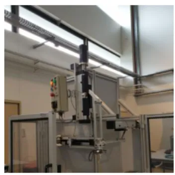
To create a CAD model and carry out simulations via ADAMS software, the follow-ing parameters of the Orthoglide are used. These parameters correspond to the param-eters of the prototype developed in LS2N (Fig. 6). The geometric paramparam-eters are:
1 1 2 2 3 3 0.31
LB C B C B C m, off _pat0.1m, sxsysz 1. The masses of links are: m10.396kg , m20.248kg and m30.905kg. The trajectory of the output axis P of the platform is given by its initial position Pi with the coordi-nates: xi0 , yi0 , 0
i
z and the final position Pf with the coordinates:
0.1 f
x m, yf0.07m,zf 0.11m. The corresponding input displacements are
determined via inverse kinematics:
xi0.31m,
xf 0.1812472m, yi 0.31m,0.3420294
yf m
, zi0.31m, zf 0.1749561m. The coordinates of the common
COM of the manipulator have been found: xSi0.0360334m, ySi0.0360334m,
0.0360334 Si
z m , xSf 0.0440614m , ySf 0.0853467m , zSf 0.0513056m . The traveling time of this trajectory is tf 1s.
Fig. 4. Variations of shaking forces for two studied cases.Fig. 5. Variations of
shak-ing moments for two studied cases.
Fig. 3 and Fig. 4 show the variations of shaking forces and the shaking moments for two studied cases: 1) the displacement of the platform of the unbalanced manipulator by the straight line with fifth order polynomial profile and 2) the generation of the motion via the displacement of the manipulator center mass by “bang-bang” profile.
The simulation results show that the shaking force has been reduced up to 31%. Compared to the increase of the shaking moment of the balancing by adding counter-weights, the shaking moment has a reduction of 30%. Another advantage of this method is its simplicity and versatility. In the case of changing trajectory, it is just necessary to provide the initial and final coordinates of the end-effector, calculate the input parameters according to the proposed method and implemented in the manipula-tor control system.
4
Conclusion and future works
It is known that the shaking force balancing by counterweights mounted on the links is more appropriate for serial and planar parallel manipulators. It is much more diffi-cult for spatial parallel manipulators. Therefore, in this paper, an alternative method based on optimal acceleration control of the common COM is discussed. The object
Fig. 6. The prototype of the Orthoglide (LS2N).
of study is the spatial 3-DOF parallel manipulator known as Orthoglide. The suggested balancing technique consists in the fact that the Orthoglide is controlled not by applying platform trajectories but by planning the displacements of the total mass center of moving links. The trajectories of the total mass center of the manipulator are de-fined as straight lines and are parameterized with “bang-bang” profile. Such a control approach allows the reduction of the maximum value of the center of mass. The numerical simulations show the efficiency of the proposed method.
8
Future works concern now the experimental validation of the suggested balancing technique via tests that will be carried out on the prototype of the Orthoglide devel-oped in LS2N (Fig. 6).
References
1. Filaretov, V.F., Vukobratovic, M.K.: Static balancing and dynamic decoupling of the motion of manipulation robots. Mechatronics 3(6), 767-783 (1993).
2. Bayer, A., Merk, G.: Industrial robot with a weight balancing system. EP Patent 2 301 727 (2011).
3. Agrawal, S.K, Fattah, A.: Reactionless space and ground robots: novel design and con-cept studies. Mechanism and Machine Theory 39(1), 25-40 (2004).
4. Fattah, A., and. Agrawal, S.K.: Design and modeling of classes of spatial reactionless manipulators. In: 2003 IEEE International Conference on Robotics and Automa-tion (ICRA), pp. 3225-3230. IEEE, Taipei (2003).
5. Fattah, A., and. Agrawal, S.K.: Design arm simulation of a class of spatial reactionless manipulators. Robotica 23(1), 75-81 (2005).
6. Wijk, V. van der, and Herder, J. L,: Dynamic Balancing of Clavel’s Delta Robot. In: Kecskeméthy A., Müller A. (eds) Computational Kinematics, pp. 315–322. Springer, Heidelberg (2009).
7. Alici G. and Shirinzadeh, B.: Optimum force balancing with mass distribution and a sin-gle elastic element for a five-bar parallel manipulator. In: 2003 IEEE International Con-ference on Robotics and Automation (ICRA), pp. 3666-3671. IEEE, Taipei (2003). 8. Ouyang, P. R., and Zhang, W. J.: A Novel Force Balancing Method for Real-Time
Con-trollable Mechanisms. In: ASME 2002, 27th Biennial Mechanisms and Robotics Confer-ence, pp. 183–190. Montreal (2002).
9. Ouyang, P. R., and Zhang, W. J.: Force Balancing of Robotic Mechanisms Based on Ad-justment of Kinematic Parameters. The Journal of Mechanical Design 127(3), 433– 440 (2004).
10. Briot, S., Arakelian, V., and Le Baron, J.-P.: Shaking Force Minimization of High-Speed Robots via Centre of Mass Acceleration Control. Mechanism and Machine Theory 57, 1– 12(2012).
11. Briot, S., Arakelian, V., Sauvestre, N., and Baron, J.-P. L.: Shaking Forces Minimization of High-Speed Robots via an Optimal Motion Planning. In: ROMANSY 18 Robot De-sign, Dynamics and Control, pp. 307–314. Springer, Vienna (2010).
12. Arakelian, V.: Design of Partially Balanced 5R Planar Manipulators with Reduced Center of Mass Acceleration (RCMA). In: Parenti-Castelli V., Schiehlen W. (eds) ROMANSY 21 - Robot Design, Dynamics and Control, vol 569, pp. 113–122. Springer, Udine (2016). 13. Arakelian, V., Geng, J., and Fomin, A. S.: Minimization of Shaking Loads in Planar Par-allel Structure Manipulators by Means of Optimal Control. Journal of Machinery Manu-facture and Reliability 47(4), 303–309 (2018).
14. Geng, J., and Arakelian, V.: Design of Partially Balanced Planar 5R Symmetrical Parallel Manipulators via an Optimal Motion Planning. In: Uhl, T. (eds) Advances in Mechanism and Machine Science. IFToMM 2019, vol 73, pp. 2211–2220. Springer, Krakow (2019).
15. Geng, J., and Arakelian, V.: Partial Shaking Force Balancing of 3-RRR Parallel Manipu-lators by Optimal Acceleration Control of the Total Center of Mass. In: Kecskeméthy A., Geu Flores F. (eds) Multibody Dynamics 2019. ECCOMAS 2019, vol 53, pp. 375–382. Springer, Duisburg (2019).
16. Wenger, P., and Chablat, D.: Kinematic Analysis of a New Parallel Machine Tool: The Orthoglide. In: Lenarčič J., Stanišić M.M. (eds) Advances in Robot Kinematics, pp. 305– 314. Springer, Dordrecht (2000).
17. Chablat, D., and Wenger, P.: Architecture Optimization of a 3-DOF Translational Parallel Mechanism for Machining Applications, the Orthoglide. IEEE Transactions on Robotics and Automation 19(3), 403–410 (2003).
18. Pashkevich, A., Chablat, D., and Wenger, P.: Kinematics and Workspace Analysis of a Three-Axis Parallel Manipulator: The Orthoglide. Robotica 24(1), 39–49 (2006). 19. Arakelian, V., and Briot, S.: Balancing of Linkages and Robot Manipulators: Advanced
Methods with Illustrative Examples. Springer, Switzerland (2015).
20. Khalil, W., Dombre, E.: Modeling, Identification and Control of Robots. Hermès, Paris (2003). Sylvain Guegan ?