HAL Id: hal-00468122
https://hal.univ-brest.fr/hal-00468122
Submitted on 30 Mar 2010
HAL is a multi-disciplinary open access
archive for the deposit and dissemination of
sci-entific research documents, whether they are
pub-lished or not. The documents may come from
teaching and research institutions in France or
abroad, or from public or private research centers.
L’archive ouverte pluridisciplinaire HAL, est
destinée au dépôt et à la diffusion de documents
scientifiques de niveau recherche, publiés ou non,
émanant des établissements d’enseignement et de
recherche français ou étrangers, des laboratoires
publics ou privés.
Spurious Responses Suppression of Parallel
Coupled-Lines Microstrip Bandpass Filters: Comparison
and Improvements of Planar Approaches
Marc Le Roy, André Pérennec
To cite this version:
Marc Le Roy, André Pérennec. Spurious Responses Suppression of Parallel Coupled-Lines Microstrip
Bandpass Filters: Comparison and Improvements of Planar Approaches. International Journal of
Microwave Computer-Aided Engineering, 2007, 17 (1), pp.104-109. �10.1002/mmce.20204�.
�hal-00468122�
Spurious responses suppression of parallel Coupled-Lines
Microstrip Bandpass Filters: comparison and improvements
of planar approaches
Marc Le Roy, André Pérennec
LEST (Laboratoire d’Electronique et Systèmes de Télécommunication) – UMR CNRS 6165.
Université de Bretagne Occidentale, 6 avenue Le Gorgeu, CS93837, 29238 Brest cedex 3.
ENSTBr, technopole Brest-Iroise, CS83818, 29238 Brest cedex 3, France.
Abstract – In this paper, three methods to reject the first spurious harmonic in parallel-coupled microstrip filters are investigated. The authors proposed an extension of these approaches to also suppress the second unwanted passbands while keeping the initial passband practically unchanged. Then, two of these techniques are combined to achieve a wider upper stopband. Indeed, the sinusoidal perturbation technique is well combined with overcoupled end sections to reject the first three spurious passbands of an order three filter. A comparison of simulations and experimental results is made, with a discussion on each method efficiency and possible applications to higher order filters.
Keywords: band-pass filters, parallel coupled microstrip lines, spurious-harmonic suppression, optimization.
I. INTRODUCTION
Microstrip coupled-lines bandpass filters are widely used due to simple synthesis procedure and easy and low cost implementation. Designers can found synthesis equation in many microwave books or used built-in procedure in CAD microwave circuit software. But, this kind of filter suffers from spurious responses that limit their integration in RF frond end of microwave wireless systems. Indeed, these systems require filters with high selectivity and wide stopband while microstrip coupled-line filters exhibits their first spurious passband at twice the
passband frequency fc. Theses harmonics of the
operating frequency and the asymmetry of the passband are due to a difference between the phase velocities of even and odd-modes in each microstrip coupled-line section. This phase velocity difference comes from different field distributions for even and odd-modes in the inhomogeneous microstrip media. Designers sometimes react by using a low-pass filter behind a bandpass filter which, of course, increases the circuit size drastically.
In general, three ways exists to reduce the spurious harmonics: equalizing the length view for each mode, decreasing the inhomogeneity of the media, and creating stopband or transmission zeros with additional elements/parameters at spurious passbands.
To equalize phase velocities and symmetrize the passband, overcoupling [1-2] is introduced at the end
of the resonators to extend the odd-mode traveling path at the first spurious. Wiggly [3] or corrugated lines [4] are also used to equalize the traveling routes of the modes. But following that technique a perfect 2nd harmonic cancellation is quite difficult to obtain because of empirical synthesis and a lack of layout generation facilities. Capacitors may also be used to extend the odd-mode traveling path.
The second approach consists in a modification of the propagation media, for example with suspended substrate [5], or multilayer technologies [6] and also with anisotropic media. These technological proposals modify the microstrip topology with certainly higher manufacturing costs or even with integration compatibility problems. In the third category, sinusoïdal perturbations [7] which periods are calculated following Bragg’s law are added on coupled lines to create a stopband at spurious frequencies. Sometimes also called wiggly lines, different periods may be applied to achieve multispurious suppression. Stepped impedance resonator (SIR) filters [8] may also be merged into this kind of approach with broad stopband but with not also widespread synthesis method. Periodic patterns etched in the ground plane [9], for example uniplanar compact photonic bandgap (UC-PBG) structures, is another way to improve the stopband responses of microstrip coupled-lines filter responses. Defect ground structures following several possibilities bring solutions to attenuate harmonics. Capacitive termination of parallel
coupled lines with folded open stub has also been investigated recently [10].
This non-exhaustive list identifies the major and most efficient possibilities. From three of the most efficient ones that doesn’t need to modify the propagation media nor the ground plane, our purpose is here to improve their efficiency and to bring new design approaches and advices to filter designers. The first investigated technique is the overcoupled end resonator one which will be extended to reject the first two harmonics for an order three filter. Then, a new simple concept introducing open stub at the end of the first coupled sections for the same filter will be compared to the first proposal. The third technique applied to the order three starting filter will associate overcoupled end resonator and sinusoidal perturbation to achieve three spurious harmonics suppression. Moreover, for this latter, we propose to use new hierarchical model of non-uniform symmetrical coupled-lines to make easier their simulation and layout generation. Circuit and electromagnetic (EM) simulations will be compared to experimental results. A final comparison on filter results, available number of spurious suppression for a given order, easy design and technological sensibility will be carried out.
II. SPURIOUS SUPPRESSION IN PARALLEL-COUPLED MICROSTRIP FILTERS USING THREE DIFFERENT TECHNIQUES
2.1 Initial filter design
Following the classical design equations, the initial Chebyshev bandpass filter was designed for a WiFi application with a bandwidth from 5.180 to 5.805 GHz (802.11 a-H&L band). This 11.4 % relative bandwidth matches the range of microstrip coupled-line bandpass filter capacities. We deliberately chose a third-order filter realized on an alumina substrate (h = 0.635 mm, r = 9.6, metallization thickness t = 5
m, tan 0.004) to place this study under initial strong constraints. All the filters and layouts presented in this paper have been made on this substrate. The suppression or compensation of harmonics is indeed more difficult when the microstrip subtrate permittivity is high since the difference in phase is ruled by r. A low filter order
also restricts the designer freedom degrees to achieve multispurious suppression. Figure 1 shows the circuit and electromagnetic S11 and S21 parameters.
Figure 1: Filter’s layout, EM (thick lines) and circuit
(thin -S21- and dashed -S11- lines) simulated
S-parameters.
These responses will be the reference for the whole of the paper.
2.2 Parallel-coupled Microstrip filter with over-coupled end sections
2.2.1 First spurious response suppression
Overcoupled sections introduced at the end of coupled-lines has been initially proposed by A. Riddle [1] and recently enhanced [2], and constitute one of the most efficient and older technique to reject the first harmonic in microstrip coupled-lines bandpass filters. This topology extends the odd mode length to compensate the phase velocity difference between modes. In an ideal case, when the ratio R = re/ro is equal to 1, the S21 parameter of a
coupled-line section shows a transmission zero at 2.fc where
fc is the central frequency of the desired passband. re
and ro are respectively the even and odd mode
permittivities. As experienced in [2], R increases for a micostrip coupled-lines section, and so the transmission zero moves to higher frequencies. Adding over-coupled section at the end of the input/ouput coupled lines allows getting a coupling length longer than /4 and then shifts the transmission zero to lower frequency. So, the over-coupled section length is determined to place this zero at the spurious frequencies. The equation (1) proposed in [1] allows the transmission zero determination but in many cases, the over-coupled length is estimated empirically through series of graphs of transmission zeros location versus coupling
length [11].
l
l
Z
Z
o e oo oe
sin
sin
(1)2.2.2 First and second spurious responses suppression
In the initial method, the identical overcoupled length introduces a transmission zero at the same frequency. We propose here to dissymmetrize the filter and place the transmission zeros of these two overcoupled length respectively at 2.fc and 3.fc to
reject the first two spurious harmonics. Consequently, the physical dimensions has also been simultaneously optimized (breaking the filter symmetry) to keep the initial passband response unchanged. The layout is presented in figure 2 and the corresponding circuit and EM responses are compared to the circuit objective response and to measurements in figure 3.
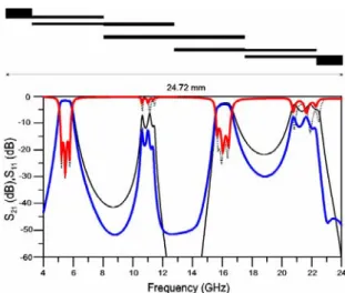
Figure 2: Asymmetrical overcoupled bandpass filter
layout.
The two spurious passbands are rejected, from more than 25 dB for the first one and from 20 dB for the second and the matching in the band is better than -10 dB. The S21 parameter is relatively flat in the band
with losses at 2.8 dB at least.
Figure 3: Experimental (thick lines) and EM (S21 in
thin line) simulated S-parameters. In-band measured parameters compared to the objective S21 parameter.
The 3 dB bandwidth is slightly reduced, both in EM and measurement responses (extending from 5.2 to 5.88 GHz) compared to circuit forecasts. For an order three filter, another overcoupled section could be applied at its center. But, many optimizations have shown that this brings no improvement in the filter response or in the out of band behavior.
2.3 Parallel-coupled Microstrip filter with open-stub at the input sections. First and second spurious responses suppression
As for overcoupled sections, open stubs are applied to reject both the first and second harmonics. When open stubs are introduced at the end of the first coupled sections, the passband is gently affected and can be recovered with only few tunings. To reject the first harmonic and the second harmonic, the stubs have a length of /4 for the frequency 2.fc and 3. fc
respectively, where the transmission zeros have to be placed. So, the dimensional parameters can be quickly optimized to fit the objective while keeping the filter symmetry
After tuning these lengths and the other filter dimensional values, the figure 4 layout is obtained. The experimental results (figure 5) show a quite good agreement compared to the simulation ones and to the ideal filter responses both in the band and outside.
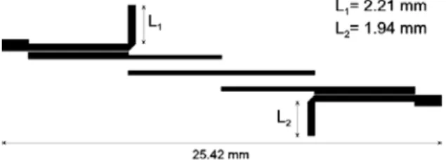
Figure 4: Filter layout with two suppressed
harmonics by different open-stubs.
In the passband, the measured S11 parameter is under
-14 dB and the S21 parameter exhibits losses around
1.7 dB. The first harmonic is attenuated by 34 dB and the second one by 21 dB.
Figure 5: Experimental (thick lines) and EM (S21 in
thin line) simulated S-parameters. In-band measured parameters (thick lines) compared to the objective S11 parameter (thin line).
2.4 Parallel-coupled Microstrip filter with sinusoidal perturbation and over-coupled end sections for multispurious rejection
From section 2-2, it comes evident that only two spurious can be rejected with overcoupled sections for a third order filter. This approach, excepted for the overcoupled sections, leaves the filter unchanged and thus allows a combination with other techniques and particularly with perturbation of the coupled-lines sections. Sinusoidal perturbations have been proposed in [11] and applied to obtain multispurious rejection; exactly 5 spurious passbands for an order-seven filter. Of course, only two spurious could be rejected for an order three. So we propose here to combine overcoupled sections and sinusoidal perturbation to reject three harmonics.
The authors have already used non-uniform coupled-line in microstrip filter design [12]. In fact, we get analytical solution for S-parameters for cubic-spline interpolated transmission-line (coupled or single). Then, arbitrary-shape lines have been simulated and designed with a self-made software. However, each circuit design required tedious software modification, particularly for layout generation. Moreover, losses were not taken into account. So, the cubic spline interpolation of non-uniform lines bas been included in a commercial software (ADS) to ensure compatibility with CAD circuit tools. In fact, we have developed new models of non-uniform structures [13] with a 3-level hierarchical approach which are based on built-in component at the lower level. These models guarantee an easy manipulation in the CAD circuit software, allow accurate circuit simulations and fits well with optimization process. The first step consists in the overcoupled-end sections design to reject the first harmonic. Then, the sinusoidal variation around the original strip width is
introduced. To reject the kth harmonics of the
passband centered at fc, the initial sinusoidal
perturbation period L is calculated following Braggs law:
k
L
L
R(2)
where LR is the resonator length. 1.5 sinusoidal
periods have been applied to the two coupled-lines
end-sections (lengths referred to LE in Fig. 6)
suppresses the 3.fc passband whereas that of 2
periods to the two central sections (lengths referred
to LC) rejects the 4.fc harmonic. From [7], the
equation (3) expressed the strip width variation wi(z)
for the ith coupled lines section and for a given
modulation percentage Mi(%):
i i i i iL
z
2
cos
.
100
(%)
M
1
w
)
z
(
w
(3) Where i is the initial phase, wi is the strip width ofthe conventional filter and Li is the period of the
perturbation applied to the ith section. Three spurious responses for only a third order filter has been achieved with the combined use of overcoupled resonators and strip width modulation. The hierarchical models allowed an optimization of the non-uniform strip width to fit the objective. Finally, after optimization and tuning, the modulation percentage is of 80 % for all the sections and the numbers of perturbation periods are slightly above and under 1.5, respectively for the central sections and for the end-sections. An automatic layout (figure 6) has been made as easily as for the other filters.
Figure 6: Filter layout with two combined
approaches: overcoupled end sections and nonuniform periodic perturbation. In equation (3), i
takes the values 160, 45, 230 and 43 for the different coupled sections.
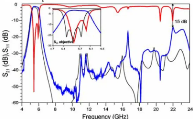
The circuit and EM simulations are both compared to the initial objective and to measurements up to 24 GHz (figure 7). The simulations show a rejection of the three harmonics from more than 27 dB. On the other hand, the third harmonics is only rejected from 15 dB in experimental results.
Figure 7: Experimental (thick lines) and EM (S21 in
thin line) simulated S-parameters. In-band measured parameters (thick lines) compared to the objective
S11 parameter (thin line). Insertion losses are 1.5 dB
at least with return losses below -12 dB.
III. DISCUSSION ON FILTERS RESULTS AND COMPARISON OF THE DIFFERENT METHOD PERTINENCE
To compare the performance filters and thus the different rejection techniques, we have set the following criteria: first, the in-band response (matching in the band, transmission losses, flatness and agreement with the objective); secondly, the out-of-band behavior (rejection level and number of suppressed harmonics); the design simplicity and the dimensional sensibility will also be reviewed, as well as the relation between filter order and number of rejected harmonics.
The stub approach presents the best in-band behavior and; the nonuniform one, the worst, particularly for the frequency centering. In this last case, no retro-optimization has been proceeded to correct the open-end effect models for three coupled-lines and may justify this frequency shift. Designers should be aware of the importance of this final dimensional readjustment to correct some circuit models. The transmission losses are practically identical for nonuniform and stub techniques and higher from about 1 dB for overcoupled sections. Moreover, the technological implementation inaccuracies have then more influences on the filter response. Indeed, for this latter case, the microstrip line width has been narrowed during the optimization process to achieve multi-rejection which amounts to changing the image impedances [2] to improve the rejection level. Moreover, the technological implementation inaccuracies have then more influences on the filter response.
Again, the out of band rejection level are higher with open stub, both for the second and third harmonics while the two other techniques show rather similar levels. In fact, transmission peaks occur due to dysynchronization of transmission zeros. For overcoupling and open-stubs, the third spurious harmonics appears above -10 dB near 20.6 GHz. With a nonuniform perturbation of 1.5 periods for all the coupled sections, a higher rejection level for the first harmonic could be obtained.
The quickest and simplest design process is unquestionably with open-stub because of well-know synthesis equations and of an optimal solution very close to the initial design. At first sight, the sinusoidal perturbation approach seems more tedious to implement but the nonuniform hierarchical models developed for the occasion are universal tools that should be available in usual CAD software.
From these first considerations, associating open-stub and sinusoidal perturbations seems logically the better solution to achieve more than two spurious harmonic suppressions. However, strip width widening near the chamfered microstrip bends may introduce spurious coupling when overcoupling does not interfere with sinusoidal perturbations.
For higher order filter, the periodic perturbation technique has showed its potential [7] in multispurious rejection. The two other techniques are obviously restricted to two harmonics at the most but leave the designer other degrees of freedom. Moreover, many applications require a symmetrical passband response and only one or two harmonics suppression.
A size comparison highlights almost identical filters length, around 25.4 mm with identical 50 access lines of 1.5 mm length. The combine approach one is slightly shorter due to an increased wave traveling time in nonuniform coupled-lines. The stubs in the second technique can be folded to reduce the overall filter width.
IV. CONCLUSION
We proposed a new method with open stubs and improvements in the two other techniques (overcoupled end sections and period perturbation) to get multispurious rejection in microstrip coupled-line bandpass filter. The different methods performances were investigated and compared on the basis of the same initial filter for WiFi application. First, two harmonics were rejected and then the third one with a dual approach. The simplest and efficient method consists in open-stub placed symmetrically at the end of the first coupled-line sections. Three microstrip prototypes were designed and experimentally characterized to validate the suggested concepts. This techniques panel brings designers some advices and flexibilities for a wide range of applications. Moreover, symmetrical perturbation may be applied to hairpin filter and the non-uniform hierarchical models would facilitate the design of microwave systems requiring non-uniform lines such as wideband couplers, nonuniform match tapers in microstrip and coplanar waveguide or impedance steps with reduced radiation at millimeter frequencies.
REFERENCES
1. A. Riddle, “High Performance Parallel Coupled Microstrip Filters”, IEEE Microwave Theory and Techniques Symposium Digest, vol.1, pp. 427-430, 1988.
2. J-T. Kuo, S-P. Chen, and M. Jiang, “Parallel-Coupled Microstrip Filters With Over-“Parallel-Coupled End Stages for Suppression of Spurious Responses”, IEEE Microwave and Wireless Components Letters, vol.13, n°10, pp. 440-442, Oct. 2003.
3. S.Uysal, “Nonuniform Line Microstrip Directional couplers and Filters”, Norwood, Artech House, 1993.
4. J-T. Kuo, W-H. Hsu, and W-T Huang, “Parallel Coupled Microstrip Filters With Suppression of Harmonic Response”, IEEE Microwave and Wireless Components Letters, vol.12, n°10, pp. 383-385, Oct. 2002.
5. T.N. Ton, Y.C. Shih, and L.Q, Bui, “Broadband Bandpass Harmonic Reject Filters”, IEEE Microwave Theory and Tech. Symposium, pp. 387-389, 1987.
6. J-T. Kuo, and M. Jiang, “Enhanced Microstrip Filter Design With a Nonuniform Dielectric Overlay for Suppressing the Second Harmonic Response”, IEEE Microwave and Wireless Components Letters, vol.14, n°9, pp. 419-421, Sept. 2004.
7. T. Lopetegi, A. G. Laso, F. Falcone, F. Martin, J. Bonache, J. Garcia, L. Pérez-Cuevas, and M. Sorolla, “Microstrip “Wiggly-Line” Bandpass Filters With Multispurious Rejection”, IEEE Microwave and Wireless Component Letters, Vol. 14, pp. 531-533, Nov. 2004.
8. J-T. Kuo, and E. Shih, “Microstrip Stepped Impedance Resonator Bandpass Filter with an
Extended Optimal Rejection Bandwidth”, IEEE Transactions on Microwave Theory and Techniques, Vol. 51, Issue 5, pp. 1554 – 1559, May 2003. 9. F-R. Yang, K-P. Ma; Y.Qian, and T. Itoh, “A Uniplanar Compact Photonic-Bandgap (UC-PBG) Structure and its Applications for Microwave Circuit”, IEEE Transactions on Microwave Theory and Techniques, Vol. 47, Issue 8, pp. 1509 – 1514, Aug. 1999.
10. P. Cheong, S-W. Fok, K-W. Tam, “Miniaturized parallel coupled-line bandpass filter with spurious-response suppression”, IEEE Transactions on Microwave Theory and Techniques, Vol. 53, Issue 5, pp.1810 – 1816, May 2005.
11. M. Jiang, M-H. Wu, and J-T. Kuo, “Parallel-Coupled Microstrip Filters with Over-“Parallel-Coupled Stages for Multispurious Suppression”, IEEE Microwave Symposium Digest, 2005.
12. M. Le Roy, A. Pérennec, L.C. Calvez, and S.
Toutain “ The continuously varying transmission
lines technique – Application to filter design ”, IEEE MTT,vol. 47, n° 9, part I, September 1999, pp. 1680, 1687
13. M. Le Roy, and A. Pérennec, “Novel Circuit Models of Arbitrary-Shape Line: Application to Parallel Coupled Microstrip Filters with Suppression of Multi-Harmonic Responses”, EuMC 45, Paris , Oct. 2005
BIOGRAPHIES
Marc Le Roy was born in Brest,
France, on November 21, 1970. He received the Ph.D. degree in electronics from the University of Bretagne Occidentale, Brest, France, in 1999. From 1995 to 1999, he was with the LEST (Laboratory for Electronics and Telecommunication Systems), Centre National de la Recherche Scientifique
(UMR CNRS 6165), Brest. His research activities deal with time- and frequency-analysis method applied to design microwave matching networks and filters. He is “Maître de conferences” since 1999 and rejoins the LEST in 2003. His main research interests concern the modelization and design of periodic structures for optical and microwave systems, and metamaterials.
André Pérennec was born in
Quimper, France, on November 8, 1960. He received the Ph.D degree in electronics from the "Université de Bretagne Occidentale" (France) in 1988. Presently, he is “Maître de conférences” at the University of Brest, in the Laboratory for Electronics and
Telecommunication Systems (LEST, UMR CNRS 6165), Brest, France. His research interests are in the active and passive device microwave area and include amplifier design (low-noise and broad-band), and filters. He has also worked on optoelectronic devices, such as LASER command circuit and transimpedance amplifiers. Actually, his main research interests concern the metamaterials.