HAL Id: hal-00820657
https://hal.archives-ouvertes.fr/hal-00820657
Submitted on 10 Mar 2020
HAL is a multi-disciplinary open access
archive for the deposit and dissemination of
sci-entific research documents, whether they are
pub-lished or not. The documents may come from
L’archive ouverte pluridisciplinaire HAL, est
destinée au dépôt et à la diffusion de documents
scientifiques de niveau recherche, publiés ou non,
émanant des établissements d’enseignement et de
Experimental analysis of microwave backscattering on a
wave tank
Nicole Beaucoudrey (de), François Poulain, Guillaume Lirzin, Marc Brunet,
Laurent Davoust, Jean-Marc Rousset, Félicien Bonnefoy
To cite this version:
Nicole Beaucoudrey (de), François Poulain, Guillaume Lirzin, Marc Brunet, Laurent Davoust, et al..
Experimental analysis of microwave backscattering on a wave tank. European Conference Ocean &
Coastal Observation Sensors and observing systems, numerical models & information Systems, Jun
2010, Brest, France. �hal-00820657�
Experimental Analysis of Microwave Backscattering
on a Wave Tank
Nicole de Beaucoudrey
1, François Poulain
1, Guillaume Lirzin
1, Marc Brunet
1,
Laurent Davoust
2, Jean-Marc Rousset
2, Félicien Bonnefoy
21
IREENA, Fédération CNRS Atlanstic, Université de Nantes, Polytech’Nantes, La Chantrerie, BP 50609, 44306 Nantes
2
Laboratoire de Mécanique des Fluides, CNRS, Ecole Centrale de Nantes, 1 rue de la Noé, BP 92101, 44321 Nantes
Abstract-In order to validate models of electromagnetic wave
scattering by rough surfaces, a laboratory experimental setup of microwave scattering by a water surface is implemented above a wave tank. This wave tank facility allows to produce controlled waves and, therefore, to acquire signals with known conditions. The current monostatic configuration permits to record the signal backscattered after reflection from the water surface. Measurements are acquired for several angles of view and for various conditions of waves. The analysis of measurements permits to study the effect of electromagnetic parameters (frequency, incidence angle of antennas, ...) and hydrodynamic parameters (wave type, height and wavelength, ...).
I. INTRODUCTION
The study of electromagnetic scattering by natural rough surfaces has a large number of applications, for example in remote sensing of the ocean, to detect targets on the sea (ships, drifting objects, ...) or to extract environmental parameters (ocean state, salinity, oil spills, …). In order to evaluate the electromagnetic scattering of rough surfaces such as the sea, scattering models have been developed for many years [1]–[5]. To validate the reliability of results calculated by scattering models, it is useful to compare them with experimental results. It is difficult not only to have at our disposal such measurements in real conditions, but even more to know precisely the geophysical parameters in such cases (sea state, ...). A laboratory experimental setup is therefore an optimal tool to acquire measurements with known conditions. For this, we use the wave tank of the Laboratoire de Mécanique des Fluides of Ecole Centrale de Nantes. The experiment in a wave tank permits to control the shape of produced waves. The goal is to get the values of the hyperfrequency reflectivity of a water surface as a function of its roughness, for different directions of observation. In the future, a bistatic configuration will be used, i.e. the two antennas (the transmitter and the receiver) will be in different locations. The measurement process will consist in positioning an antenna in a particular incidence angle and in changing the observation angle of the other antenna.
In this first stage, we realized a setup on the wave tank for a monostatic configuration, i.e. with both antennas in the same location [6,7]. Several experiments were carried out and measured data sets are now available for comparison with simulated results.
We present the experimental setup and the measurements. The analysis of these experimental data allows to study the effect of electromagnetic as well as hydrodynamic parameters.
II. EXPERIMENTAL SETUP
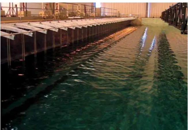
The wave tank is a rectangular pool (length 50m, width 30m, depth 5m) of fresh water. 48 paddles are located on one side of the basin and a wave absorber on the opposite side. A specialized software controls these paddles for generating three-dimensional waves. Fig. 1 shows the side of the basin with the paddles generating waves.
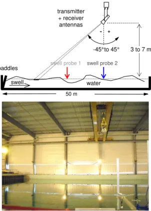
Fig. 2 gives a general view of the microwave system installed above the wave tank. The microwave instrumentation apparatus is installed on a platform hanged under a handling crane (Fig. 3). The two antennas (one transmitter and one receiver) are holded in a rotating frame and connected to a vector network analyzer (Agilent PNA 8364). A computer, located at ground level, remotely controls the microwave apparatus: first, it steers the antennas in the chosen direction, then it drives the analyzer and performs acquisition and storage of electromagnetic measurements.
The pyramidal horn antennas (205mm x 155mm) have a 3dB aperture of 12° (at 9 GHz, in V plane). Their altitude over the mean water surface varies from 3 m to 7 m. Antennas are linearly polarized and can be positioned in either vertical or horizontal orientation (i.e. with the electric field constrained in either vertical or horizontal plane).
swell water -45° to 45° transmitter + receiver antennas 50 m paddles 3 to 7 m - + swell probe 2 swell probe 1
Figure 2 : General wiew of the experimental setup.
Figure 3 : Microwave experimental setup on the wave tank.
III. MEASUREMENTS
• Microwave parameters
We operate in X band (8-12 GHz, with 40 MHz frequency step, thus 101 frequency samples). The two antennas are colocated and we choose co-polarization configuration, either VV or HH. The two-antennas device can be rotated in the vertical plane defined by the swell direction (along the length
of the basin). Their orientation can be controlled with 0.2° angular step. The acquisition frequency is 20 Hz (sampling time of measurements of 0.05 s), thus allowing to follow temporal variations of the swell.
• Hydrodynamic parameters
Experiments have been conducted either above a still water surface or above two-dimensional waves, propagating in one direction (along the basin length). In order to do this, the 48 paddles move in conjunction. Generated waves are either regular (Stokes waves) or irregular (random waves, with a Bretschneider spectral distribution). The wave height (defined respectively as the peak-to-trough distance for regular waves or as the significant wave height for irregular waves) is ranging from 5 cm to 35 cm. The wave frequency is equal to
0.5 or 0.7 Hz, thus corresponding to a wavelength, L=g/(2πf2),
nearly equal to 6 m or 3 m.
Experiments were carried out with various conditions during the measurement campaign. About 700 sets of data were acquired (each sequence being composed of 100 to 5000 time-samples for each electromagnetic frequency).
IV. ANALYSIS OF MEASUREMENTS
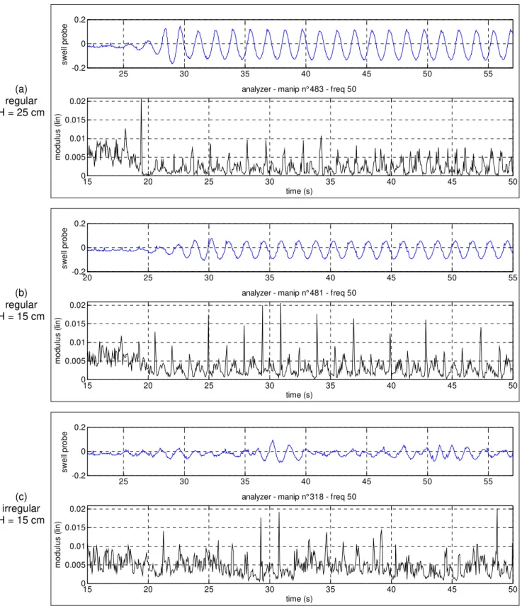
Fig. 4 presents some examples of acquired raw data as a function of time. For each case, the upper curve shows the swell amplitude, measured with a swell probe, and the lower curve plots the modulus of the ratio of the received electric field to the transmitted one. For these three experiments, the antennas inclination is 0° (normal incidence to the still water surface), microwave frequency is 10 GHz in VV polarisation. The hydrodynamic wave frequency is 0.7 Hz (wave period = 1.43 s, wave wavelength L = 3.18 m). Fig. 4(a) is for a regular wave, with peak-to-trough height H = 25 cm, Fig. 4(b) is for a regular wave, with H = 15 cm, Fig. 4(c) is for an irregular wave, with significant height H = 15 cm. The
time scales are identical for hydrodynamic and
electromagnetic measurements, but they are not synchronized. In these examples, experiments start before the wave generator activation, therefore we can see the response of the still water at the beginning of each measurement.
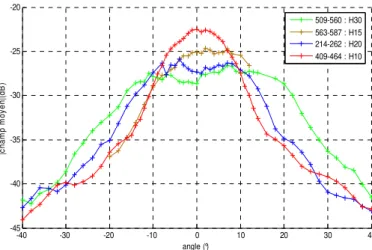
These raw data are then averaged in time to give a response for each swell characteristic and for each inclination of antennas. Fig. 5 presents such an angular response for regular swells with various peak-to-trough heights (10,15,20,30 cm), with the same wave frequency 0.7 Hz, the microwave frequency 10 GHz and antennas in VV polarization. The incident angle ranges between -40˚ and +40˚.
Radiation pattern of antennas must be taken into account to retrieve the Radar cross section of rough surfaces from such angular responses. Indeed, we can see the angular response of a still water surface, on Fig. 6(a) for antennas in VV polarization and on Fig. 6(b) for antennas in HH polarization. In each case, this response is compared to the radiation pattern of antennas, measured in an anechoid chamber.
(a) regular H = 25 cm (b) regular H = 15 cm (c) irregular H = 15 cm 25 30 35 40 45 50 55 -0.2 0 0.2 s w e ll p ro b e 15 20 25 30 35 40 45 50 0 0.005 0.01 0.015 0.02
analyzer - manip n° 318 - freq 50
m o d u lu s ( lin ) time (s) 20 25 30 35 40 45 50 55 -0.2 0 0.2 s w e ll p ro b e 15 20 25 30 35 40 45 50 0 0.005 0.01 0.015 0.02
analyzer - manip n° 481 - freq 50
m o d u lu s ( lin ) time (s) 25 30 35 40 45 50 55 -0.2 0 0.2 s w e ll p ro b e 15 20 25 30 35 40 45 50 0 0.005 0.01 0.015 0.02
analyzer - manip n° 483 - freq 50
m o d u lu s ( lin ) time (s)
Figure 4 : Measures as a function of time. Microwave parameters: antennas inclination = 0°, frequency = 10 GHz, polar VV. Hydrodynamic parameters : wave frequency = 0.7 Hz. (a) regular wave, peak-to-trough H = 25 cm, (b) regular wave, peak-to-trough H = 15 cm, (c) irregular wave, significant H = 15 cm.
-40 -30 -20 -10 0 10 20 30 40 -45 -40 -35 -30 -25 -20 |c h a m p m o y e n |( d B ) angle (°) 509-560 : H30 563-587 : H15 214-262 : H20 409-464 : H10
Figure 5 : Electromagnetic response as a function of antennas inclination (frequency = 10 GHz, polarization VV), for regular swells (frequency 0.7 Hz)
with peak-to-trough heights (H = 10,15,20,30 cm).
-60 -40 -20 0 20 40 60 -50 -45 -40 -35 -30 -25 -20 -15 -10 -5 0 fréquence 10 GHz |c h a m p m o y e n |( d B ) n o rm a lis é angle (°) VV : eau calme VV : antenne chambre (a) VV polar -60 -40 -20 0 20 40 60 -50 -45 -40 -35 -30 -25 -20 -15 -10 -5 0 fréquence 10 GHz |c h a m p m o y e n |( d B ) n o rm a lis é angle (°) HH : eau calme HH : antenne chambre (b) HH polar V V H H
Figure 6 : Electromagnetic response as a function of antennas inclination (freq. = 10 GHz), above a still water surface. Polarization: (a) VV and (b) HH.
Comparison with the antenna radiation pattern, measured in an anechoid chamber for the corresponding polarization.
Fig. 6(a), for VV polarization, shows a very good agreement between the response above a plane surface (the still water) and the radiation pattern of antennas. On the contrary, Fig. 6(b), for HH polarization, is quite different for absolute value of angles greater than 20°. This exhibits a coupling between the two antennas, due to the electric field distribution in the aperture plane of the antennas. This effect will be corrected for future experiments.
V. CONCLUSION
This experimental setup of microwave scattering by a water surface has been implemented above a wave tank. Measurements acquired for various hydrodynamic and electromagnetic conditions of waves can be used as a database for further analysis. In particular it can be compared to simulation results obtained from electromagnetic models [8,9].
ACKNOWLEDGMENT
This study is funded by the french Region Pays de la Loire through the DIMBAHO project (DIffusiomètre Micro-Ondes sur BAssin de HOule).
REFERENCES
[1] P. Beckman and A. Spizzichino, “The Scattering of
ElectromagneticWaves from Rough Surfaces”, New York: Pergamon, 1963.
[2] A. Ishimaru, “Wave Propagation and Scattering in Random Media”, New York: Academic, 1978, vol. 2.
[3] F. G. Bass and I. M. Fuks, “Wave Scattering from Statistically Rough
Surfaces”, Oxford: Pergamon Press, 1979.
[4] J. A. Ogilvy, “Theory of Wave Scattering from Random Rough Surfaces”, New York: Adam Hilger, 1991.
[5] K. F. Warnick and W. C. Chew, “Numerical simulation methods for rough surface scattering: topical review,” Waves Random Media, vol. 11, R1–R30 (2001).
[6] F. Poulain, N. de Beaucoudrey, S. Loin, N. Déchamps, J.M. Rousset, “Expérimentation sur bassin de houle d'un diffusiomètre micro-ondes monostatique”, OCOSS 2007, Paris, juin 2007.
[7] F. Poulain, N. de Beaucoudrey, M. Brunet, G Lirzin, J.M. Rousset, L. Davoust, “Etude expérimentale de la rétrodiffusion micro-ondes sur bassin de houle”, Journées Nationales Microondes, Grenoble, mai 2009. [8] A. Gharib, F. Poulain, C. Bourlier, N. de Beaucoudrey, “Contribution of
the sea surface in monostatic radar echoes”, International Radar
Conference, RADAR’09, Bordeaux, octobre 2009.
[9] A. Gharib, F. Poulain, C. Bourlier, N. de Beaucoudrey, F. Bonnefoy, “Time electromagnetic response of a controlled regular wavefield in a wave basin for a monostatic configuration”, OCOSS 2010, Brest, juin 2010.