Science Arts & Métiers (SAM)
is an open access repository that collects the work of Arts et Métiers Institute of Technology researchers and makes it freely available over the web where possible.
This is an author-deposited version published in: https://sam.ensam.eu
Handle ID: .http://hdl.handle.net/10985/6742
To cite this version :
Li LU, Eric SEMAIL, Luc KOBYLANSKI, Xavier KESTELYN - Flux-Weakening Strategies for a Five-Phase PM Synchronous Machine - In: EPE 2011 - 14th European Conference on Power Electronics and Applications, United Kingdom, 2011-09 - Proceedings of the 2011-14th European Conference on Power Electronics and Applications (EPE 2011) - 2011
Flux-Weakening Strategies for a Five-Phase PM Synchronous Machine
Li Lu
(1)(2), Eric Semail
(1), Luc Kobylanski
(2), Xavier Kestelyn
(1)(1)Arts et Métiers ParisTech, (2)Valeo Engine Electrical Equipment
8, boulevard Louis XIV, 59046, Lille, France, 2, rue andré boulle, 94000, Créteil, France
Tel : +33/(0)-148982809
Fax : +33/(0)-148982720
E-mail : [email protected]
Acknowledgements
This work is part of the project ’MHYGALE’ (Mild Hybrid for Generalization) with funding by ADEME (French Agency for Control and Saving Energy) within Valeo Engine Electrical Equipment.
MHYGALE ADEME
The study of this paper is included in the the project MHYGALE proposed by Valeo, which is is to develop a hybridization solution called "Mild" (mild hydride) affordable for the greatest number with a significant impact on worldwide CO2 emissions. This solution, based on a high-power electric machine
driven by belt, offers start / stop, regenerative braking and torque assist. This booster torque allows motors highly "downsized" to maintain equivalent performance with current engines, thereby making the generalization for an additional acceptable.
Abstract
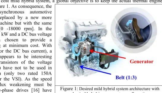
In order to get a low cost mild hybrid system, a global objective is to keep the actual thermal engine architecture as in Figure 1. As consequence, the
current clawpole synchronous automotive generator must be replaced by a new more powerful electrical machine but with the same large speed range [0 -18000 rpm]. In the project, a power of 15 kW and a DC bus voltage of 60V have been chosen to provide a regenerative breaking at minimum cost. With this payload (250A for the DC bus current), a five-phase machine appears to be interesting because MOSFET transistors of the voltage source inverter (VSI) have not to be used in parallel configuration (only two rated 150A transistors per leg for the VSI). As the speed range is large, a flux weakening must be applied. As the five-phase drives [16] have more degrees of freedom than three-phase ones
[13], different flux weakening strategies can be considered. The aim of this paper is to compare one of them.
Keywords
Flux weakening, Five-Phase PM Synchronous Machine(Five-Phase PMSM), Maximum Torque Per Ampere(MTPA), base speed, back-EMF
I. Model of a Five-Phase PM Synchronous Machine(Five-Phase PMSM)
In order to deduce a control structure for a five-phase machine, a modelling that points out the degrees of freedom will be presented.
Figure 1: Desired mild hybrid system architecture with classical belt driven generator configuration
Belt (1:3)
1. Multisystem of a Five-Phase PM Synchronous Machine
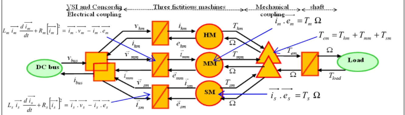
A five-phase PM synchronous machine can be split into three fictitious machines according to families back-EMF(back-electromotive force) harmonics using Concordia transformation [1][2]. In detail, the back-EMF harmonics corresponding in each fictitious machine: main machine (MM), secondary machine(SM) and homopolar machine (HM) are in Table 1. Each equivalent machine is characterised by its inductance (resp. Lh , Lm and Ls), resistance (resp. Rh , Rm and Rs), and back-EMF (resp. e , hm emm
G and esm
G
). Thus the MM (the SM and the HM) produces Tmm (Tsm and Thm) torque mainly thanks to the first harmonic (third harmonic, fifth harmonic) of the back-EMF [3][4]. An Energetic Macroscopic Representation (EMR) [4] is given in Figure 2. This synthetic graphic representation is used to deduce systematically the control structure of the 5-phase machine. It then appears that it is sufficient to implement two usual vector control algorithms already developed for 3-phase machines [3]. In EMR [4], the electrical coupling (two interleaved orange squares) takes into account the 5-leg VSI [15] and the generalised Concordia transformation. The mechanical coupling (two interleaved orange triangles) simply means that the total torque is the sum of the two 2-phase machine and a 1-phase machine torque contributions (MM, SM and HM).
Homopolar Machine(HM)
Main Machine(MM) Secondary
Machine(SM)
5.10,…,
5h1, 9,11,…,
5h±13, 7,13,…,
5h±22. Control structure of a Five-Phase PM Synchronous Machine in flux-weakening
HM can only create torque pulsations because it is a one-phase machine. So we assume that in our case machines are star-coupled without neutral output: the current in HM is zero. Then we have only two fictitious machines given in Figure 2 called MM and SM that can be defluxed. Three possible combinations of flux weakening can be defined:
a) Flux weakening in MM b) Flux weakening in SM
c) Flux weakening in MM and SM
d) In this paper, the flux weakening in MM will be done.
II. Flux weakening control strategies
In order to define the flux weakening criterions, two electrical constraints are introduced: DC bus voltage vbus and maximum thermal current Imax_thermal. With these two limits, flux weakening sequences
can be distinguished. In the next paragraphs, only one case is given with experimental results: the flux weakening control is applied in MM and Maximum Torque Per Ampere(MTPA) control is kept in SM.
Figure 2 :Multi-machine Energetic Macroscopic Representation of a 5-phase machine
1. MTPA(Maximum Torque Per Ampere)
1.1 Review of the control structure
As far as the stator voltages do not saturate the DC-bus voltage [7]and the stator currents do not exceed Imax_thermal the maximum thermal current, then MTPA control is used. In a five-phase machine the MTPA
control consists in ensuring collinearity between the current vector iGand the back-EMF vector [3][5]. Table 1 :Distribution of the EMF harmonics in the fictitious machines for a Five-Phase PM
Synchronous
Ω = m m m e T i .
[ ]
m m m m m m m m m dt R i i v i e i d i L + 2= . − .[ ]
s s s s s s s s s R i i v i e dt i d i L + 2= . − . s s = s Ω T e i . sm mm hm em T T T T = + +Figure 3 : Base speed according to E3/E1
Figure 4 : Base speed according to E3/E1 and phase-shift
Moreover, when only harmonics 1, 3 and 5 are considered for the back-EMF, the previous MTPA strategy is equivalent to the classical MTPA strategy developed for three-phase machines. So we have only to apply MTPA strategy for SM and MM machines (Figure 7).
1.2 Impact of ratio between 3rd and 1st harmonic of back-EMF
It is well kown [1] that for 3-phase wye-coupled machine, it is possible to optimize by a ratio 115 % the ‘use’ of the DC-bus voltage [11][12] by injection of third harmonic component in the voltage reference [10]. For a 5-phase machine, the third harmonic is the main harmonic of the SM machine. As consequence the injection of a third harmonic of voltage will have also an impact on the torque if the emf has a third harmonic component E3 [8][9].
In Figure 3 it is possible to see this impact of the ratio E3/E1, considering a range between 0 % and 50 %
on the achievable maximum speed that can be obtained for the maximum torque without saturation of the VSI. After this speed, also called the base speed, the torque must be weakened if the speed must be increased. This base speed obtained with a ratio equal to zero between the third and first harmonic of emf is taken as reference speed in the paper.
We observe that we can have a higher base spped than 1.15 in a range of E3/E1 ratio between 0.16 and
0.26. From the E3/E1 ratio equals 0.35, we have a base speed lower than 1. In other words, if one wants a
larger base rate in this machine, it is better to have the E3/E1 ratio between 0.16 and 0.26.
0 0.05 0.1 0.15 0.2 0.25 0.3 0.35 0.4 0.45 0.5 0.9 0.95 1 1.05 1.1 1.15 1.2 E3/E1 Ba se Spee d 0 0.1 0.2 0.3 0.4 0.5 0 28 57 86 115 143 172 200 0.7 0.8 0.9 1 1.1 1.2 E3/E1 Phase-shift(degree) Ba s e Sp e e d
In fact, it is not only the ratio E3/ E1 that impacts on the base speed but also the phase-shift ψ between the
first and the third harmonic. The previous results have been given for a phase-shift equal to zero (look at Figure 3). In Figure 4, the results are given with both ψ and E3/ E1.
It is observed that near the phase-shift equals zero and 115 degree in a range of ratio E3/ E1 between 0.16
and 0.26, we have a base speed greater than 1.18. In other words, the base speed in this machine is greater if phase-shift and ratio of E3/ E1 are in these two areas.
In conclusion, it appears that for given inductance values the best couple of values is (E3/ E1, ψ)=(0.2, 0)
and (E3/ E1, ψ)=(0.2, 115). The improvement is then equal to 18 % in comparison with a 5-phase
Figure 5 : Base speed according to E5/E1
Figure 6 : Base speed according to E3/E1 and phase-shift
1.3 Impact of the fifth harmonic of back-EMF
The harmonic that plays the same role for a 5-phase machine than the third harmonic for a 3-phase machine is the fifth harmonic. Nevertheless, as it is studied in [1], its impact is less important.
In order to confirm the point for the value of the base speed, we have considered a ratio E5/ E1 between 0
% and 20 % for the optimal point previously determined considering the ratio E3/ E1 equals 0.2.
We find in Figure 5 that the base speed stays at 1.06 in a range of ratio E5/ E1 between 0.02 and 0.18,
and close to the ratio 0185 the base speed reaches the maximum 1.15.
In Figure 6 we can see that the impact of phase-shift ψ between the first and the fifth harmonic has almost no influence on the base speed. It’s still the ratio E5/ E1 dominating the evolution of base speed.
0 0.02 0.04 0.06 0.08 0.1 0.12 0.14 0.16 0.18 0.2 1 1.02 1.04 1.06 1.08 1.1 1.12 E5/E1 Ba s e S peed 0 0.05 0.1 0.15 0.2 0 28 57 86 115 143 172 2001 1.05 1.1 1.15 E5/E1 Phase-Shift(degree) Ba s e S p e e d B_v>0 :
The stator voltages are unsaturated at level of DC bus voltage vbus
B_v=0 :
The stator voltages are saturated at level of DC bus voltage vbus
B_i>0 :
The stator currents are unsaturated at level of maximum thermal current Imax_thermal B_i=0 :
The stator currents are saturated at level of maximum thermal current Imax_thermal
Figure 7: Stateflow of particular flux weakening strategies in of a Five-Phase PM Synchronous Machine
MTPA in MM and SM Flux Weakening strategy of Limited Voltage (FWLV) in MM and MTPA in SM Flux Weakening strategy of Limited Current (FWLC) in MM and MTPA in SM Start B_v=0 and B_i>0 B_v>0 and B_i>0 B_v=0 and B_i>0 B_v>=0 and B_i=0 B_v>0 and B_i>0 B_v>=0 and B_i=0
T3
T2
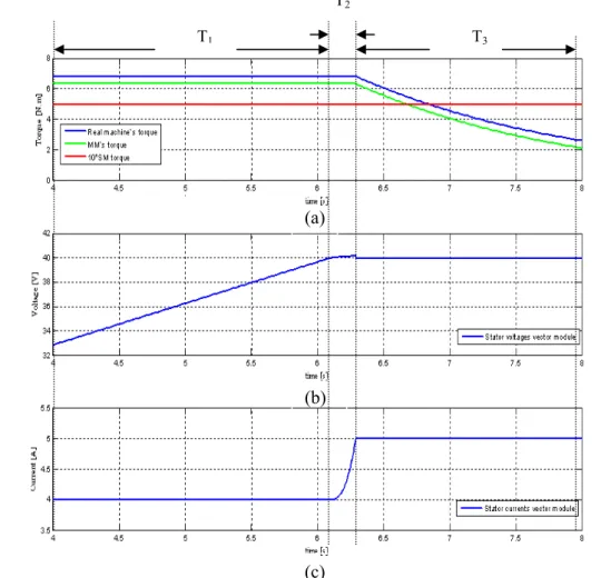
Figure 8: Simulation results of a five-phase drive. (a) Torques in real machine, MM and SM. (b) Stator voltages vector module. (c) Stator currents vector module.
2. Flux Weakening strategy of Limited Voltage(FWLV)
This strategy is applied in the case given in Figure 7 when the stator voltages saturate at vbus DC bus
voltage value and stator currents are below Imax_thermal thermal current [5][6]. In detail, in the Park
reference frame associated with MM [6], the direct axis current id is used to decrease the magnetic flux
along the direct axis of MM. The quadrature axis current iq keeps the same value to maintain not only
machine’s performance but also algorithm continuity [14][17].
3. Flux Weakening strategy of Limited Current(FWLC)
This strategy is used in the case given in Figure 7 when the stator currents saturate at thermal current Imax_thermal [5][6]. The necessary value of the direct axis current id is applied and then
2 2
max_ thermal d
q I i
i = − .
4. Simulation and Experimental results of flux weakening control
The strategies described in paragraphs II 1,0 and 3 has been applied in simulation and on an experimental drive. Simulation results are given in Figure 8 and experimental results are given in Figure 9.
According to the voltage limit given in Figure 8 (b) and current limit given in Figure 8 (c), We can see the evolution of magnetic torque given in Figure 8 (a). In detail, the MTPA control is applied during the period T1 when there is neither voltage saturation nor current saturation. During the period T2, the FWLV is applied: the voltage is maximum, current is increasing and torque is constant. During the period T3, the FWLC is applied: the current is maximum, the flux decreases thoroughly, and the total torque falls to a lower scale.
The optimal on-line control technique has been implemented on a wye-connected four-pole five-phase DC Brushless machine with trapezoidal EMF supplied by a 5-leg Voltage Source Inverter (VSI). The
T1
(a)
(b)
T3
T2
load torque is generated by a magnetic powder brake associated with an inertial load. A torquemeter SCAIME DR2513 is installed between the motor and the load in order to measure the mechanical torque. Figure 10 gives a snapshot of the experimental test-bed.
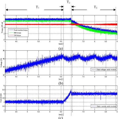
We observe that there is a very good correspondence between simulation (Figure 8) and experiment(Figure 9). We found also three cases of operation (Figure 7) in these two figures.
T1
Figure 9: Experimental results of a five-phase drive. (a) Torques in real machine, MM and SM. (b) Stator voltages vector module. (c) Stator currents vector module.
(a) (b) (c) VSI 5-phase PMSM Mechanical load Torquemeter DSpace controller
III. CONCLUSION
In this paper, we studied the influences on the variation of ratio and angle shift between different harmonics of emf. We found the optimal values for each case. The flux-weakening on different machines are introduced fictitious. The flux-weakening on MM is detailed into three strategies according to two electrical constraints: the DC-bus and the maximum thermal current. The results in simulation and in experiment are compared and we obtained good correspondence.
References
[1] E. Semail, X. Kestelyn, A. Bouscayrol, “Right Harmonic Spectrum for the back-electromotive force of a n-phase synchronous motor”, IAS 2004, IEEE Industrial Application Society Annual Meeting, Seattle, Washington October 3-7, 2004, CD-ROM
[2] F. Scuiller, E. Semail, J.F. Charpentier, “Multi-criteria based design approach of multiphase permanent magnet low speed synchronous machines”, IET Trans. Electric Power Applications, Mar 2009, vol 3, no. 2, pp. 102-110.
[3] E. Semail, X. Kestelyn, A. Bouscayrol, “Sensitivity of a 5-phase Brushless DC machine to the 7th harmonic of the back-electromotive force”, PESC 2004, IEEE Power Electronics Specialists Conference, Aachen, Germany, June 20-25 2004, CD-ROM.
[4] C. C. Chan, A. Bouscayrol, K. Chen, “Electric, Hybrid, and Fuel-Cell Vehicles: Architectures and Modeling”, IEEE trans. on Vehicular Technology, Feb. 2010, vol. 59, no. 2, pp. 589-598.
[5] L. Parsa, N. Kim and H. Toliyat, “Field Weakening Operation of a High Torque Density Five Phase Permanent Magnet Motor Drive,” IEEE International Electric Machines and Drives Conference, pages 1507-1512, May 2005.
[6] Z. Sun, J. Wang, W. Jewell, D. Howe, “Enhanced Optimal Torque Control of Fault-Tolerant PM Machine Under Flux-Weakening Operation”, IEEE Trans. Ind. Electron., vol. 57, no. 1, pp. 344-353, Jan. 2010. [7] E.Levi, D.Dujic, M.Jones, G.Grandi, “Analytical determination of DC bus utilization limits in multi-phase
VSI supplied AC drives,” IEEE Trans. on Energy Conversion, vol. 23, no. 2, 2008, pp. 433-443
[8] A. Iqbal, E. Levi, M. Jones, S.N. Vukosavic, "Generalised Sinusoidal PWM with Harmonic Injection for Multi-Phase VSIs," PESC '06, IEEE Power Electronics Specialists Conference, June 2006
[9] H. M. Ryu, J. H. Kim, S. K. Sul, “Analysis of multiphase space vector pulse-width modulation based on multiple d-q spaces concept,” IEEE Trans. on Power Electron., vol. 20, no. 6, 2005, pp. 1364-1371. [10] R. Bojoi, A. Tenconi, F. Profumo, G. Griva, D. Martinello, "Complete analysis and comparative study of
digital modulation techniques for dual three-phase AC motor drives," Power Electronics Specialists Conference, 2002. pesc 02. 2002 IEEE 33rd Annual , vol.2, no., pp. 851-857 vol.2, 2002
[11] R. Bojoi, M. Lazzari, F. Profumo, A. Tenconi, "Digital field-oriented control for dual three-phase induction motor drives," Industry Applications, IEEE Transactions on , vol.39, no.3, pp. 752-760,
June 2003
[12] R. Bojoi, F. Farina, M. Lazzari, F. Profumo, A. Tenconi, "Analysis of the asymmetrical operation of dual three-phase induction machines," Electric Machines and Drives Conference, 2003. IEMDC'03. IEEE International, vol.1, no., pp. 429-435 vol.1, 1-4 June 2003
[13] A. Boglietti, R. Bojoi, A. Cavagnino, A. Tenconi, "Efficiency Analysis of PWM Inverter Fed Three-Phase and Dual Three-Three-Phase High Frequency Induction Machines for Low/Medium Power Applications," Industrial Electronics, IEEE Transactions on , vol.55, no.5, pp.2015-2023, May 2008
[14] O. Ojo, G. Dong, “Generalized discontinuous carrier-based PWM modulation scheme for multi-phase converter-machine systems,” in Proc. of IEEE Ind. Appl. Soc. Annual Meeting (IAS), 2005, pp. 1381.
[15] O. Ojo, G. Dong, Z. Wu, “Pulse-width-modulation for five-phase converters based on device turn-on times,” in Proc. of IAS 2006, 8-12 October, Tampa, Florida, USA, pp. 627- 634.
[16] D. Casadei, G. Serra, A. Tani, L. Zarri, “General inverter modulation strategy for multi-phase motor drives,” in Proc. of ISIE 2007, 4-7 June, Vigo, Spain, pp. 1131–1137.
[17] S.M. Sue, C.T. Pan, “Voltage-Constraint-Tracking-Based Field-Weakening Control of IPM Synchronous Motor Drives,” IEEE Trans. Ind. Electron., vol. 55, no. 1, pp. 340.