• Aucun résultat trouvé

Update on the LBTI: a versatile high-contrast and high-resolution infrared imager for a 23-m telescope

N/A
N/A
Protected

Academic year: 2021

Partager "Update on the LBTI: a versatile high-contrast and high-resolution infrared imager for a 23-m telescope"

Copied!
8
0
0

Texte intégral

(1)

Improving the performances of current optical interferometers & future designs Proceedings of Haute Provence Observatory Colloquium (23-27 September 2013) Edited by L. Arnold, H. Le Coroller & J. Surdej

Update on the LBTI: a versatile high-contrast and high-resolution infrared imager for a 23-m telescope

D. Defr`ere1 , P. Hinz1 , A. Skemer1 , P. Arbo1 , V. Bailey1 , G. Brusa1 , T. Connors1 , E. Downey1 , O. Durney1 , J. Eisner1 , P. Grenz1 , B. Hoffmann1 , J. Hill1 , J. Leisenring1 , T. McMahon1 , B. Mennesson3 , R. Millan-Gabet2 , M. Montoya1 , M. Nash1 , M. Skrutskie4 , R. Sosa1 , and V. Vaitheeswaran1 1

Steward Observatory, University of Arizona, 633 N. Cherry Avenue, 85721 Tucson, USA

2

NASA Exoplanet Science Center (NExSci), California Institute of Technology, 770 South Wilson Avenue, Pasadena CA 91125, USA 3

Jet Propulsion Laboratory, California Institute of Technology 4800 Oak Grove Drive, Pasadena CA 91109-8099, USA

4

University of Virginia, Department of Astronomy, 530 McCormick Road, Charlottesville, VA 22904-4325, USA

Abstract. The Large Binocular Telescope Interferometer (LBTI) is a strategic instrument of the LBT designed for high-sensitivity, high-contrast, and high-resolution infrared imaging of nearby nearby planetary systems. It combines the two 8.4-m apertures of the LBT in various ways including direct (non-interferometric) or Fizeau imaging, non-redundant aperture masking, and nulling interferometry. First fringe-tracked observations were obtained in December 2013. We report in this paper on the status and recent progress of the LBTI with a particular focus on interferometry.

1. Introduction

The LBTI is a NASA-funded interferometric instrument designed to coherently combine the two 8-m primary mirrors of the LBT for sensitivity, high-contrast, and high-resolution infrared imaging (≥3µm). It is developed and op-erated by the University of Arizona and based on the heritage of the Bracewell Infrared Nulling Cryostat (BLINC) on the MMT (see e.g., Hinz et al. 2000). It is equipped with two scientific cameras: LMIRcam (the L and M Infrared Camera) covering the 3-5µm range and NOMIC (Nulling Optimized Mid-Infrared Cam-era) covering the 7-25µm range. The main scientific goals are to determine the brightness and prevalence of exozodiacal dust and image giant planets around nearby main-sequence stars. Two surveys are currently being carried out in that respect: an exozodiacal dust survey called HOSTS (Hunt for Observable Signa-tures of Terrestrial Planetary Systems, Weinberger et al. 2014) and a planet

(2)

38 D. Defr`ere et al.

Figure 1.: Components of the LBTI shown with the optical path through the beam combiner and the NIC cryostat. Starlight is reflected on LBT primaries, secondaries, and tertiaries before coming into this diagram on the top right and top left. The visible light is reflected on the entrance window and used for adaptive optics while the infrared light is transmitted into LBTI, where all subsequent optics are cryogenic. The beam combiner directs the light with steerable mirrors and can adjust pathlength for interferometry. Inside the NIC cryostat, 3-5µm light is directed to LMIRCam for exoplanet imaging, 2.0-2.4µm light is directed to the phase sensor, which measures the differential tip/tilt and phase between the two primary mirrors, and 8-13µm light is directed to NOMIC for Fizeau imaging or nulling interferometry.

survey called LEECH (LBTI Exozodi Exoplanet Common Hunt, Skemer et al. 2014). We describe in this paper the different interferometric modes implemented in the LBTI and show some early results.

2. The instrument

The LBTI consists of a universal beam combiner (UBC) located at the bent center Gregorian focal station and a cryogenic Nulling Infrared Camera (NIC). The UBC provides a combined focal plane from the two LBT apertures while the precise overlapping of the beams is done in the NIC cryostat. The optical design for NIC uses reflective optics to accommodate the wide wavelength range that the LBTI covers. Both the short and the long wavelength channels have an intermediate pupil plane for cold baffling, and nulling beam combination or coronagraphy, as well as an intermediate focal plane for insertion of slits or obscuration spots.

(3)

Status of the LBTI 39

Figure 2.: Optical layout of NOMIC. The light enters from the left side, is reflected by the beam diverter and reimaged by LWBC 1. A set of flat mirrors overlap the two beams on a beamsplitter. One output of the interferometer is relayed via LWBC 2 to the science detector.

Besides the two science cameras, the NIC cryostat also houses a K-band fast readout camera (Phasecam) to sense phase variations between the LBT apertures and carry out fringe tracking. A range of cryogenic actuators and alignment mechanisms have been developed to carry out fine alignment of the interferometer and to feed the several channels of NIC. Figure 1 shows the optical path through the UBC and NIC. The three cameras are described hereafter.

– LMIRCAM is the mid-infrared optimized science camera equipped with a Hawaii-2RG detector which has a very fine plate-scale (0.01arcsec/pixel) to sufficiently sample the LBT’s interferometric PSF. It contains various filter options, including L-band, M-band, PAH-on (at 3.3 µm), PAH-off, Brα, and H2O ice. A grism for low resolution spectroscopy (R∼350), a vector-vortex coronagraph (AGPM, Mawet et al. 2013), and non-redundant aper-ture masks are also available. The first observations made by overlapping the light from both telescopes have been published recently (Skemer et al. 2014).

– NOMIC is the long-wavelength camera used in particular for nulling inter-ferometry. Figure 2 shows the optical path from the combined focal plane to the Raytheon Aquarius Detector. The detector is a 1024x1024 Blocked Impurity Band (BIB) hybrid array with 30-µm pixels. The optics provides a field of view of 12 arcsecs with pixels of 0.018 arcsecs in size. λ/D for an individual aperture is 0.27 arcsecs at 11µm. For Fizeau interferometry with the two apertures, it is 0.10 arcsecs (or 5.5 pixels).

(4)

40 D. Defr`ere et al.

Figure 3.: Optical layout of Phasecam. The outputs of the nulling beamsplitter are directed via several lenses to two quadrants of a PICNIC detector.

– PHASECAM is the near-infrared camera equipped with a PICNIC detector that is used for fringe sensing. It receives the light from both interferometric outputs whether the long wavelength channel is in nulling or imaging mode. The only difference is a dichroic which is inserted after the LW biconic 1. A set of reimaging lens are placed at the pupil to create a FOV of 10 arcsecs. Several filter wheels are placed in the beam. One provides for varying neutral density filter to be placed in the the wheel. A second wheel provides for filtering or insertion of a low-dispersion prism into the beam. The reimaging lens are mounted on a wheel to allow for insertion of a second set of lenses that can reimage the pupil, rather than the star.

More information about the cameras and the design of NIC can be found in Hinz et al. (2008) and Skrutskie et al. (2010).

3. Interferometric observations

The LBT is an ideal platform for interferometric observations because the in-dividual telescopes are installed on a single steerable mount. This design does not require long delay lines and contains relatively few warm optical elements which provides an exceptional sensitivity. The interferometric combination can be performed in image plane for Fizeau imaging or in pupil-plane for nulling in-terferometry. These two different modes are described hereafter and illustrated with some commissioning results.

(5)

Status of the LBTI 41

Figure 4.: Fizeau interferometric PSF at 4.0 µm and 11.0 µm obtained respec-tively with LMIRcam and NOMIC.

3.1 Fizeau interferometry

Fizeau interferometric imaging is available on both science channels separately or simultaneously. Since the high angular resolution direction is always parallel to the horizon and perpendicular to the parallactic angle, aperture synthesis is achieved by sky rotation and provides the resolution of 22.8-m telescope. Fig. 4 shows the interferometric PSF obtained at 4.0 µm with LMIRcam (left) and at 11.0 µm with NOMIC (right).

3.2 Nulling interferometry

Nulling interferometry is a technique proposed by Bracewell 35 years ago to image extra-solar planets (Bracewell 1978). The basic principle is to combine the beams coming from two distinct telescopes in phase opposition so that a dark fringe appears on the line of sight, which strongly reduces the stellar emission while transmitting the flux of off-axis sources located at angular spacings which are a multiple of λ/b (where b is the distance between the telescope and λ the wavelength of observation). The technique has now been successfully used on sky both in the near-infrared (Mennesson et al. 2011) and the mid-infrared (e.g., Stock et al. 2010, Millan-Gabet et al. 2011) and the performance required to directly detect exoEarths demonstrated on laboratory testbeds (Martin et al. 2012).

Nulling interferometry with the LBTI was first achieved in September 2012 without fringe and tip/tilt stabilization. The null measurements were randomly fluctuating between constructive and destructive interference, following the ran-dom atmospheric pathlength variations. In December 2013, first fringe-tracked nulling observations were obtained on several bright stars. A 4-min null sequence is shown in Fig. 6 with its corresponding null histogram. The goal of these ob-servations was to demonstrate null stabilization rather than a deep null depth (the optical pathlength difference coarsely adjusted). Tools to optimize the null depth and stability are currently being tested.

(6)

42 D. Defr`ere et al.

Figure 5.: Example of non-redundant aperture masking observation with the LBTI. The figure shows the power spectrum of an unresolved calibrator (top) and a bright, previously imaged, YSO (bottom). The latter is heavily resolved especially on baselines longer than approximately 10m.

3.3 Non-redundant aperture masking

The L-band channel of NIC currently contains two non-redundant aperture masks, one with 12 holes and one with 24 holes. An example of observation is shown in Fig. 5 for two relatively bright objects (L<4): an unresolved calibrator (top) and a bright, previously imaged, YSO (bottom) which is heavily resolved especially on baselines longer than about 10m. The observations were achieved without AO correction nor fringe tracking and a short enough integration time was used to freeze the atmospheric piston. AO correction and fringe-tracking are now available and will enable the same sort of data for fainter objects. Image reconstruction is currently under progress.

3.4 Fringe tracking

Fringe tracking is performed in the near-infrared portion of NIC and uses the PICNIC camera described above (see optical layout in Fig. 3). A range of optics can be used to create different setups for pathlength and tip/tilt sensing, including the use of relative intensity between the two interferometric outputs, dispersed fringes, or an image of the combined pupils. A large (80 pixel) pupil image of the starlight can be formed for diagnostics, as well as stellar images, and small (18 pixel) pupils. H or K band filters can be used. These various optics allow a flexible approach to phase sensing. So far, fringe sensing has been mainly performed using an image of pupil fringes (equivalent to wedge fringes). Because of dispersion between 2 µm and 10 µm in the beamsplitter, a well overlapped

(7)

Status of the LBTI 43

Figure 6.: One of the first fringe-tracked null sequence obtained on December 31st 2013 at N-band (top figure). The bottom figure shows the corresponding null histogram which peaks at a null of ∼5%.

set of images at 10 µm corresponds to a tilt difference of roughly 3 fringes across the pupil at 2 µm. This has the nice feature of providing a signal in the Fourier plane well separated from the zero-frequency component and allow us to separate tip-tilt and phase variations via a Fourier transform of the detected light. The magnitude of the Fourier transform gives a measurement of the tip/tilt while the phase of the Fourier transform gives a measurement of the optical path delay.

(8)

44 D. Defr`ere et al.

Fringe tracking has been carried out at 1kHz so far and could go as fast as 4 kHz in the near future.

4. Status and schedule

The LBTI has reached several important milestones over the past few years and is on good tracks toward routine coherent imaging observations. First fringes were obtained in October 2010, just one month after the installation on the telescope, dual-aperture AO-corrected fringes in April 2012, and first nulling observations in September 2012. The first fringe-tracked observations were obtained in December 2013 using a technique equivalent to group-delay tracking. Most of the efforts are now focused on implementing phase tracking and improving the null depth and stability.

References

Bracewell 1978, Nature, 274, 780 Hinz P. et al., 2001, SPIE, 4006, 349 Hinz P. et al., 2008, SPIE, 7013 Martin et al., 2012, AO,51, 2907 Mawet D. et al., 2013, SPIE, 8864 Mennesson et al., 2011, ApJ, 243, 178 Millan-Gabet et al., 2011, ApJ, 734, 67 Skemer A. et al., 2014, ApJ, accepted Skemer A. et al., 2014, IAU, 299, 70 Skrutskie et al., 2010, SPIE, 7735 Stock et al., 2010, ApJ, 724, 1238

Figure

Figure 1.: Components of the LBTI shown with the optical path through the beam combiner and the NIC cryostat
Figure 2.: Optical layout of NOMIC. The light enters from the left side, is reflected by the beam diverter and reimaged by LWBC 1
Figure 3.: Optical layout of Phasecam. The outputs of the nulling beamsplitter are directed via several lenses to two quadrants of a PICNIC detector.
Figure 4.: Fizeau interferometric PSF at 4.0 µm and 11.0 µm obtained respec- respec-tively with LMIRcam and NOMIC.
+3

Références

Documents relatifs

2 - Modélisation cinétique des oléfines en mélange avec les composés soufrés Le même modèle cinétique qui a permis d’expliquer la transformation des composés soufrés

itively, the scale of a defect is the smallest scale at which one sees, after blowup, non constant functions.) This suggests that boundary defects are significantly larger than

Definition 2 can be adapted in the directed square and triangular lattices; the animals thus defined are in bijection with connected heaps of dimers.. Bousquet- M´elou and

The phase 1-111 transition is presumably second order, and the discovery of two low frequency lines existing only in phase III, the frequencies of which were

In both systems a thin film emulsion of small (1 micron) latex spheres in liquid nonlinearly detects these transmitted waves in the very near field of the

The observed ν 1 6 fundamental band origin, blue-shifted by 67.15 cm − 1 relative to the degenerate HCN monomer bending band origin, provides the final significant contribution to

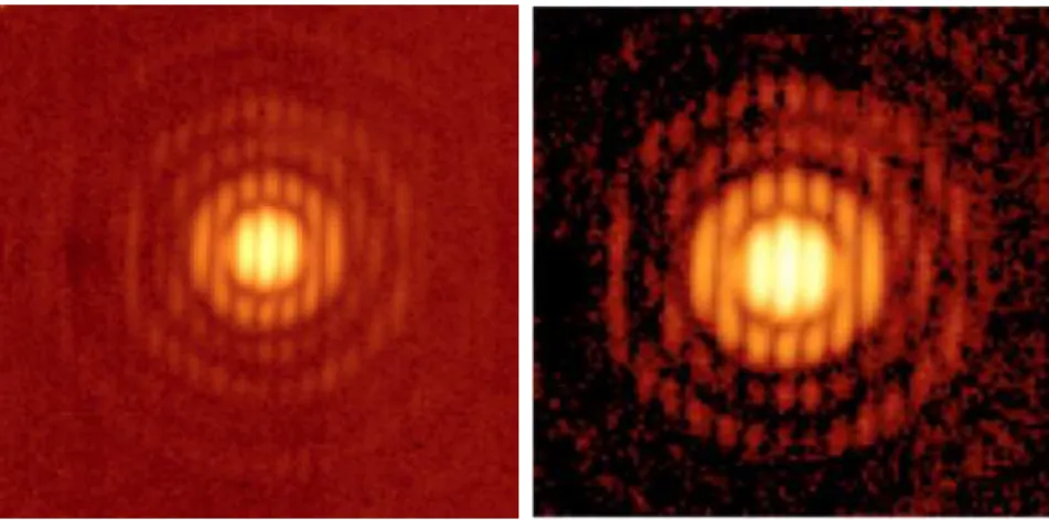
The global gain averaged across the AO-corrected field of view is improved by a factor of 2 in contrast in long exposures and by a factor of 10 in contrast in short exposures (i.e.

We consider the Directed Spanning Forest (DSF) constructed as follows: given a Poisson point process N on the plane, the ancestor of each point is the nearest vertex of N having