HAL Id: tel-02917937
https://tel.archives-ouvertes.fr/tel-02917937
Submitted on 20 Aug 2020HAL is a multi-disciplinary open access
archive for the deposit and dissemination of sci-entific research documents, whether they are pub-lished or not. The documents may come from teaching and research institutions in France or abroad, or from public or private research centers.
L’archive ouverte pluridisciplinaire HAL, est destinée au dépôt et à la diffusion de documents scientifiques de niveau recherche, publiés ou non, émanant des établissements d’enseignement et de recherche français ou étrangers, des laboratoires publics ou privés.
Receive and Transmit Spatial Modulation Techniques
for Low Complexity Devices
Ali Mokh
To cite this version:
Ali Mokh. Receive and Transmit Spatial Modulation Techniques for Low Complexity Devices. Signal and Image Processing. INSA de Rennes, 2018. English. �NNT : 2018ISAR0020�. �tel-02917937�
T
HESE DE DOCTORAT DE
L’INSA
RENNES
C
OMUEU
NIVERSITEB
RETAGNEL
OIREECOLE DOCTORALE N°601
Mathématiques et Sciences et Technologies de l'Information et de la Communication
Spécialité : Télécommunications
Receive and Transmit Spatial Modulation Techniques for Low
Complexity Devices
Unité de recherche : IETR – UMR CNRS 6164
Par
Ali MOKH
Rapporteurs avant soutenance :
Geneviève Baudoin Professeur, ESIEE, Paris
Laurent Ros Maître de conférences, HDR,
INP, Grenoble
Composition du Jury :
Jean-Pierre Cances Professeur, ENSIL, Limoges /
Président
Geneviève Baudoin Professeur, ESIEE, Paris /
Rapporteur
Laurent Ros Maître de conférences, HDR,
INP, Grenoble / Rapporteur
Marco Di Renzo Chargé de Recherche, HDR,
CNRS CentraleSupelec/ Examinateur
Michel Terré Professeur, CNAM, Paris /
Examinateur
Matthieu Crussière Maître de conférences, HDR,
INSA, Rennes / Co-encadrant
Maryline Hélard Professeur, INSA, Rennes /
Directrice de thèse
Invité
Intitulé de la thèse :
Receive and Transmit Spatial Modulation Techniques for Low Complexity Devices
Ali MOKH
En partenariat avec :
i
“To Find Your Self, Think for Yourself.”
Socrates
“They did’nt know it was impossible, so they did it.”
Mark Twain
“The most subversive people are those who ask questions.”
ii
DEDICATION
To my Parents, Wife, Daughter and my friends, To Hussein Ahmad Akhdar
Declaration of Originality
I, Ali MOKH, declare that this thesis titled, “Receive and Transmit Spatial Modulation Techniques for Low Complexity Devices” and the work presented in it are my own. I confirm that:
• This work was done wholly or mainly while in candidature for a Doctoral degree at the Institut National des Sciences Appliqués de Rennes.
• Where I have consulted the published work of others, this is always clearly at-tributed.
• Where I have quoted from the work of others, the source is always given. With the exception of such quotations, this thesis is entirely my own work.
• I have acknowledged all main sources of help.
• Where the thesis is based on work done by myself jointly with others, I have made clear exactly what was done by others and what I have contributed myself.
Ali MOKH Date: 15/11/2018
RÉSUME EN FRANÇAIS
Introduction
Dans la quatrième génération de réseaux cellulaires (4G), le Long-Term Evolution (LTE) et son extension, les systèmes LTE-Advanced, avec une interface radio avancée, com-prenant du Multiple-Input Multiple-Output (MIMO), de l’Orthogonal Frequency-Division Multiplexing (OFDM) et des technologies d’ada-ptation de liens, ont été adoptés. Les architectures 4G offrent, en plus des applications voix et données, un accès Internet à très haut débit. De cette manière, des applications exigeant un débit de données élevé sont fournies, telles que les jeux, la télévision haute définition et le cloud computing. Cependant, il y a toujours une augmentation spectaculaire du nombre d’utilisateurs qui s’abonnent chaque année aux systèmes mobiles à haut débit. De plus en plus de per-sonnes recherchent un accès Internet plus rapide en mobilité, des téléphones portables plus modernes et, en général, une communication instantanée avec les autres ou un accès à l’information. Les smartphones et les ordinateurs portables plus puissants sont de plus en plus populaires de nos jours, exigeant des capacités multimédia avancées. D’un autre côté, les réseaux 4G ont pratiquement atteint la limite théorique du débit de données avec les technologies actuelles et ne sont donc pas suffisants pour répondre aux défis susmentionnés. La cinquième génération de réseaux cellulaires (5G) devrait commencer à être deployé vers 2020 et, compte tenu de l’énorme demande de transmis-sion de données entre un grand nombre de périphériques connectés, il est largement admis que, comparé au réseau 4G, le réseau 5G devrait augmenter l’efficacité spectrale, l’efficacité énergétique, le débit de données, et le débit cellulaire moyen [1]. Le but est de connecter le monde entier et d’obtenir des communications transparentes et omni-présentes entre tous (personnes et à personnes), entre tout type de support (machine à machine), où qu’elles soient (n’importe où), à tout moment. L’un des grands défis de la prochaine 5G consiste alors à intégrer le futur réseau cellulaire un trafic de données massif issu de la communication entre les objets.
L’Internet des objets (IoT) est un des mots-clés qui représente une des évolutions de la 5G afin de connecter les objets connectés (CD) au réseau. On s’attend à ce que ces CD soient adaptés et activés avec un comportement autonome et une interconnexion sécurisée, afin d’atteindre le plus haut degré d’intelligence et d’assurer une interopé-rabilité totale. De plus, les éléments composant l’IoT seront caractérisés par de faibles ressources en termes de calcul et de capacité énergétique [2]. Donc, il est important de prendre en compte la complexité des opérations qui effectuent la transmission entre le CD et le réseau. Ainsi, l’augmentation du débit de données et de l‘efficacité spectrale,
vi RÉSUME EN FRANÇAIS
tout en minimisant la consommation d’énergie, comptent parmi les éléments clés de conception de futurs systèmes de communication sans fil.
Les coûts élevés du spectre radioélectrique, d’une part, et la consommation de bande passante par les services nécessitant un débit de données élevé, d’autre part, né-cessitent des recherches sur des techniques qui augmentent l’efficacité spectrale. Ainsi, ces dernières années, l’exploitation de la dimension spatiale (antennes multiples au ni-veau du récepteur et /ou de l’émetteur) dans les systèmes radioélectriques a fait l’objet de nombreuses recherches. En ajoutant plusieurs antennes, un degré de liberté supplé-mentaire (en plus des dimensions temporelle et fréquentielle) dans la transmission sans fil peut être offert pour permettre de transférer davantage de données d’informations. Par conséquent, une amélioration significative des performances peut être obtenue en termes de fiabilité, efficacité spectrale et efficacité énergétique.
Depuis le début des années 2000, la modulation spatiale (SM) s’est imposé comme un principe de transmission prometteur pour les appareils de faible complexité et à faible consommation d’énergie [2]. Les SM exploitent l’index de l’antenne d’émission ou des antennes de réception pour transmettre des bits d’information supplémentaires communément appelés bits spatiaux et symboles spatiaux [3]–[6]. Les premiers sché-mas SM proposés concernaient les systèmes en boucle ouverte car ils ne nécessitaient aucune connaissance de canal au niveau de l’émetteur (CSIT). Ce sont les schémas de SM à l’émission (TSM). Ils s’appuient principalement sur la stratégie de Space Shift Keying (SSK) [7]. On considère par défaut un système MIMO fortement asymétrique en SM, entre un objet et un station de base. Cette technique pourrait être utilisée pour la transmission de la liaison montante en raison de sa simplicité au niveau de l’émetteur et offre une bonne efficacité spectrale en comparaison des autres schémas de transmis-sion de type Single-Input Single-Output (SISO).
D’autre part, les principes SM peuvent être également transposés du côté du ré-cepteur, ce qui conduit au principe de Receive Spatial Modulation (RSM). Comme in-troduit dans [8], RSM peut aussi être appelé Transmit Precoding Spatial Modulation (TPSM) car il repose sur une opération de prétraitement ou de pré-codage spatial qui exploite la connaissance du canal à l’émission, afin de cibler une des antennes du ré-cepteur. Par conséquent, contrairement à TSM, qui utilise le concept SSK pour associer les bits d’information aux indices d’antenne d’émission, le RSM effectue une opéra-tion pré-SSK pour effectuer l’associaopéra-tion sur les indices de l’antenne de récepopéra-tion visée. Une détection très simple est possible au niveau de récepteur pour détecter le symbole spatial [9], [10].
Inspirée par cette technologie, le projet "Modulation Spatiale" est lancé par l’Agence nationale de la recherche (ANR) dont l’objectif est de "concevoir une nouvelle interface d’air pour Internet-des-objets mobile à intégrer dans les interfaces air futures pour les réseaux mobiles (5G) et les WLAN". cette thèse qui fait parti de ce projet, prend en compte une de la partie traitement de signal, et a étudié les performances des schémas SM côté émetteur et récepteur, dans la perspective d’offrir un système de transmission de liaison montante et descendante complet entre la station de base et le CD. Un tel système offre l’avantage d’une complexité de calcul réduite au niveau du CD, et la complexité la plus importante au niveau de la BS, avec une bonne efficacité spectrale.
RÉSUME EN FRANÇAIS vii
Chapitre 1 : Etat de l’art
Dans ce chapitre, un bref historique de l’évolution des communications sans fil est pré-senté. On explique comment l’exploitation de la dimension spatiale permet d’améliorer les performances des systèmes sans fil, ce qui a conduit les chercheurs à s’intéresser aux systèmes de communication MIMO au cours des deux dernières décennies. Le concept des systèmes MIMO et ses avantages sont présentés. Par la suite, en raison du gain de multiplexage en diversité, le concept de Spatial Modulation (SM) est présenté et il est expliqué que celui-ci fournit une transmission économe en énergie en exploitant à la fois la diversité et le gain de multiplexage. Ainsi, l’état de l’art des systèmes SM est structuré en deux parties. Dans la première partie, la technique TSM est présentée, lorsque le principe de SM est utilisé avec ou sans symboles IQ supplémentaires. Un diagramme permet de fournir un aperçu des différents schémas basés sur ce concept et leurs études de performance. Les avantages et les inconvénients de techniques TSM ont également été fournis dans ce chapitre. Dans la deuxième partie, le principe SM de réception est présenté, avec différentes méthodes de précodage. En outre, comme dans le cas TSM, une vue d’ensemble de la recherche publiée sur différents systèmes basés sur le concept de réception SM est fournie.
Chapitre 2 : Receive Antenna Shift Keying
Dans ce chapitre, le schéma de transmission Receive Antenna Shift Keying (RASK) basé sur le concept SM à la réception est évalué. Ici, l’émetteur effectue une étape de prétraitement pour cibler une antenne de réception, résultant en une efficacité spectrale égal : log2(Nr), dont l’efficacité spectrale est defini ici d’être le nombre de bit par sym-bol. Deux méthodes de précodage sont utilisées et comparées : le Zero-Forcing (ZF) et le Maximum Ratio Transmission (MRT). Du côté du récepteur, différents schémas de détection sont proposés pour chaque méthode de précodage et peuvent être classés en deux catégories : détection cohérente et non cohérente. Le premier estime le signal et sa phase, et une synchronisation de la phase entre les antennes est nécessaire, tandis que le second estime uniquement la puissance reçue.
Pour le ZF-RASK tout d’abord, i.e. un système RASK avec un précodage ZF, nous avons démontré de manière analytique que le récepteur optimal peut être réduit à un comparateur, en raison de l’absence d’interférences entre les antennes. En outre, les ré-sultats montrent que la détection cohérente a de meilleures performances mais au prix d’une complexité matérielle supplémentaire au niveau du récepteur, car une chaîne RF complète avec transition en bande de base et conversion analogique numérique est nécessaire pour chaque antenne de réception.
Dans le cas du MRT-RASK, le détecteur ML reste plus complexe et nécessitent une estimation de canal. Nous avons proposé différents détecteurs pour le système MRT-RASK qui ne nécessitent pas d’estimation de canal. La complexité de calcul a été étu-diée et comparée, et les dérivations analytiques de la BEP théorique pour certains détec-teurs ont été fournies et validées par des simulations. Afin de réduire la complexité ma-térielle du détecteur cohérent, nous avons proposé d’utiliser des commutateurs sur le récepteur, de sorte que plusieurs antennes de réception soient connectées à une même chaîne RF. Cette méthode entraîne une dégradation du SNR effectif et donc une
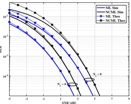
dégra-viii RÉSUME EN FRANÇAIS -5 -3 -1 1 3 5 7 9 SNR [dB] 10-4 10-3 10-2 10-1 BER ML Sim NCML Sim ML Theo NCML Theo Nr = 4 Nr = 8
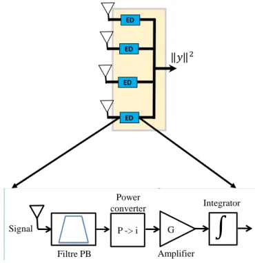
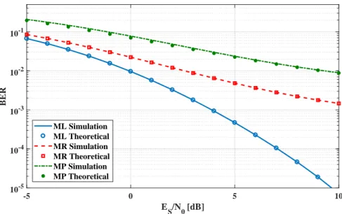
BER performance of 16×4 and 16×8 ZF-RASK systems using CML and NCML de-tectors over Rayleigh channel, simulated and theoretical results -5 0 5 10 ES/N0 [dB] 10-5 10-4 10-3 10-2 10-1 BER ML MR MRMI NCML MP
BER performance of 8×4 MRT-RASK systems using all detectors over Rayleigh channel
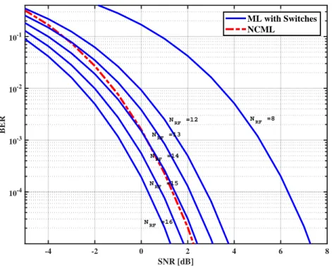
dation des performances. Ainsi, en fonction du rapport entre le nombre de chaînes RF et le nombre d’antennes de réception, le détecteur non cohérent pourrait surpasser le détecteur cohérent lorsque des commutateurs sont utilisés. Nous avons donc calculé le point d’équivalence qui donne le nombre minimum de chaînes RF nécessaires pour que le détecteur cohérent reste plus performant que le non cohérent. Enfin, le schéma RASK avec pré-codage MRT a été étudié de manière analytique dans un scénario de canal LOS. Les résultats ont été validés par des simulations et une mise en œuvre pra-tique sur plate-forme radio-logicielle.
Chapitre 3 : Extended Receive Antenna Shift Keying
Dans ce chapitre, nous avons proposé d’augmenter l’efficacité spectrale du RASK. Au lieu de cibler une seule antenne de réception, un nombre variable d’antennes de récep-tion est ciblé pour chaque durée de symbole. Ce nouveau système s’appelle ERASK. Tout d’abord, nous avons présenté le principe du schéma lorsque le précodage ZF est utilisé. Nous avons démontré que le détecteur ML peut être réduit à un détecteur de seuil d’amplitude. Un autre détecteur basé sur un seuil de puissance a également été présenté. Les dérivations analytiques du BEP pour les deux détecteurs sont fournies et validées par des simulations. Par la suite, nous avons étudié l’effet des erreurs d’es-timation des canaux et de la corrélation entre les antennes sur les performances de ZF-ERASK, par des dérivations analytiques du BEP et des simulations. De plus, les performances étudiées de l’ERASK lors du précodage MRT sont comparées à celles du ZF-ERASK. Ici, le seuil d’amplitude n’est plus le détecteur optimal, et les résultats montrent que le ZF-ERASK surpasse le MRT-ERASK lorsque le même détecteur est uti-lisé. En outre, il est montré que plus le nombre d’antennes émettrices est élevé, plus les performances de MRT-ERASK et celle du ZF-ERASK sont proches.
Enfin, nous avons proposé de transmettre des symboles IQ supplémentaires avec le symbole spatial d’ERASK, dans un système appelé Extended Receive Spatial Mo-dulation (ERSM). Comme le système ERASK utilise toutes les combinaisons possibles
RÉSUME EN FRANÇAIS ix -15 -10 -5 0 5 10 15 ES/N0 [dB] 10-6 10-5 10-4 10-3 10-2 10-1 100 BER ZF-ERASK-Nt=8 ZF-ERASK-Nt=16 ZF-ERASK-Nt=32 ZF-ERASK-Nt=64 MRT-ERASK-Nt=8 MRT-ERASK-Nt=16 MRT-ERASK-Nt=32 MRT-ERASK-Nt=64
Comparison of the BER performance of MRT-ERASK and ZF-ERASK over a Ray-leigh fading channel, Nr=2
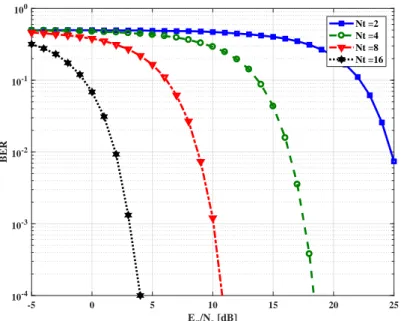
2 4 6 8 10 12 14 16 18 20 SNR [dB] 10-4 10-3 10-2 10-1 100 BER ERSM-Nr=2-QPSK ERSM-Nr=4-QPSK ERSM-Nr=2-8PSK ERSM-Nr=4-8PSK ERSM-Nr=2-16PSK ERSM-Nr=4-16PSK
BER vs SNR for a 8×2 and 8×4 MIMO ERSM, for QPSK, 8-PSK, and 16-PSK with Rayleigh fading
d’antennes ciblés, l’une d’entre elles étant de ne pas cibler une antenne de réception, dans ce cas, il est impossible d’envoyer le symbole IQ. Nous avons donc proposé d’uti-liser deux niveaux de puissance pour transmettre les deux symboles (symboles spatial et IQ). Nous avons également calculé les performances analytiques du BEP. Un rapport de puissance optimal entre les deux niveaux de puissance minimisant le BEP total a été calculé analytiquement et validé par des simulations. Les résultats montrent que lorsque le rapport optimal est utilisé, les performances de l’ERSM restent les mêmes si nous modifions la configuration du symbole, en modifiant l’ordre de la modulation IQ ou le nombre d’antennes de réception ciblées, tout en conservant la même efficacité spectrale.
Chapitre 4 : Extended Space Shift Keying
0 5 10 15 20 25 SNR [dB] 10-6 10-5 10-4 10-3 10-2 10-1 100 BER Nr=4, ML Nr=4, EQ-ML Nr=8, ML Nr=8, EQ-ML Nr=16, ML Nr=16, EQ-ML Nr=32, ML Nr=32, EQ-ML Nr=64, ML Nr=64, EQ-ML
BER performance of 2x8 ESSK system, using ML and EQ-ML detection, theoreti-cal and simulation comparison
Visualization of the transmission between Base Station and Connected Device
x RÉSUME EN FRANÇAIS
système ERASK mais appliqué à l’émetteur pour la transmission de liaison montante entre l’objet et la station de base. Un nombre variable d’antennes d’émission est activé afin d’augmenter l’efficacité spectrale globale. Nous avons étudié les performances du schéma dans le canal de Rayleigh en dérivant le BEP analytique lorsque le détecteur ML est utilisé. En outre, nous avons proposé d’implémenter une égalisation au niveau du récepteur pour détecter le symbole, en utilisant la même matrice de précodage dans la transmission descendante pour ERASK. Le résultat montre que le détecteur ML sur-passe le détecteur avec égalisation, mais que plus le nombre d’antennes de réception est élevé, plus les performances du détecteur avec égalisation et celles du détecteur ML sont proches. Enfin, nous avons vérifié la dualité d’ESSK et ERASK en liaison montante et descendante, lorsque le détecteur avec égalisation est utilisé. À la fin de ce chapitre, on a proposé un système de transmission entre une station de base et un objet connecté, basé sur le concept de la modulation spatiale, dont la complexité est réduite au niveau de l’objet.
Chapitre 5 : Beamforming Hybrid Pour Receive Antenna Shift
Keying en mmWaves
Dans ce dernier chapitre, une étude détaillée de RASK dans les systèmes mmWave a été réalisée, couvrant tous les scénarios possibles analytiquement et numériquement par rapport aux travaux existants dans la littérature. Nous avons proposé d’utiliser un beamformer hybride comprenant un beamformer analogique et un beamformer numé-rique. Dans le formateur de faisceau analogique, la méthode de formation de faisceaux LoS et la méthode de formation de faisceaux Equal Gain Transmission (EGT) ont été proposées et étudiées, tandis que le précodeur numérique est toujours le précodeur ZF. Nous avons dérivé des expressions pour l’efficacité spectrale dans le cas
d’environne-...000111 H RF Detection/ Spatial demapping 000111 RF Information source R1 R2 RF RF Spatial Modulation W Digital precoder Analog precoder FRF
Block Diagram of RASK with Hybrid beamforming
ments de canaux LoS purs pour tout scénario de déploiement possible, étant donné que deux antennes de réception existent et que l’optimisation optimale du déploiement du réseau de transmission est appliquée à la minimisation de corrélation. De même, nous
RÉSUME EN FRANÇAIS xi
avons dérivé des expressions pour le BEP dans le cas d’environnements de canaux de type LoS purs pour tout scénario de déploiement possible, étant donné que le récepteur a deux antennes de réception, et qu’un déploiement optimal du réseau de transmission est appliqué pour la minimisation de corrélation. De plus, une expression pour le BEP a été dérivée pour les environnements à trajets multiples rares ainsi qu’une analyse complète des performances réalisables du RASK dans les systèmes mmWave. Tous les modèles introduits ont été validés par analyse numérique.
Conclusion
Dans cette thèse, nous avons évalué les performances des modulations spatiales pour des transmissions vers des objets peu complexes. Des schémas de transmission en liai-son montante et en liailiai-son descendante ont été proposés et étudiés sur la base du prin-cipe SM. L’objectif principal était de minimiser la complexité de l’appareil connecté tout en offrant de bonnes performances en terme d’efficacité spectrale et de BEP. Plus spé-cifiquement, nous avons évalué les performances du schéma RASK en utilisant diffé-rentes méthodes de précodage et différents schémas de détection. En outre, le système RASK a été étudié pour des transmissions sur canaux de Rayleigh, de type LoS, ainsi que dans un environnement mmWave en utilisant la formation de faisceau hybride. De plus, un schéma étendu de RASK appelé ERASK a été proposé et étudié dans le but d’augmenter l’efficacité spectrale tout en conservant une détection de faible com-plexité sur l’objet connecté. En outre, un schéma analogue au système ERASK pour la transmission en liaison montante, appelé ESSK, a été proposé et étudié. Dans la suite, un résumé des principales contributions et conclusions de la thèse est fourni. Enfin, nous avons proposé de transmettre des symboles IQ supplémentaires avec le symbole spatial d’ERASK, appelé ERSM. Mais comme l’ERASK utilise toutes les combinaisons possibles d’antennes cibles, l’une d’entre elles étant de ne pas cibler une antenne de réception, dans ce cas, il est impossible d’envoyer le symbole IQ. Nous avons donc pro-posé d’utiliser deux niveaux de puissance pour transmettre les deux symboles (sym-boles spatial et IQ). Nous avons également calculé les performances analytiques du BEP. Un rapport de puissance optimal entre les deux niveaux de puissance minimisant le BEP total a été calculé analytiquement et validé par des simulations. Les résultats montrent que lorsque le rapport optimal est utilisé, les performances de l’ERSM res-tent les mêmes si nous modifions la configuration du symbole, en modifiant l’ordre de la modulation IQ ou le nombre d’antennes de réception ciblées, tout en conservant la même efficacité spectrale.
Acknowledgments
Firstly and foremost, I would like to express my sincere thanks, appreciation, and dee-pest gratitude to the supervisors of my PhD studies, Professor Maryline Helard and Dr. Matthieu Crussiere.
They gave me the opportunity to pursue my PhD degree, which had been one of my most desirable dreams until this moment. Therefore, the volume of my gratitude for this is unlimited. During my PhD studies, Prof Helard and Dr Crussiere were the best example of academic excellence who inspired me the most. Their insightful advice and technical guidance have shaped the way of my thinking in the most positive direction. Thank you for everything.
I am really grateful to my research coauthors during my PhD studies, Dr. Marco Di Renzo, Dr. Yvan Kokar, and Dr. Mohammad Shehata. Each one of them helped me in the most valuable way. Marco helped me to increase my research level ta a higher level thanks to his advice and technical support. Yvan simplified the way to understand some technical limitations of the implementation, and we had a great collaboration using his platform and my theoretical results. Shehata really helped me in the last stage of my PhD. Our discussions enabled me to produce the best results. My research would not be the same without them. Thank you for this.
Many thanks to Mr. Francois Yven and my fellow intern Mr. Mohammad Alawieh for helping me in evaluating my work with a practical implementation. Francois wor-ked hard to get the platform to our lab, and Mohammad did a wondefull job in 6 months to provide a successful proof of concept. Thank you guys !
A special thanks to Saja Takache, my wife’s sister, for proofreading parts of my publication. She positively affected my style of writing in an invaluable way. Thank you very much Saja.
Furthermore, I would like to acknowledge the nancial support of the French Natio-nal Agency of Research. The work presented in this thesis was supported by the ANR’s project "Spatial Modulation". In addition, I would like to thank all the people of the Spa-tial Modulation project for our three-year fruitful collaboration. The ofce hours during the past years have been uncountable. However, due to my ofce friends, Ahmad Sho-kair, Ahmad Jabban, Yehya Nasser, Wael Ayyoub, Maryam Al Hassan, Marwan Hajj, Ferdaous Mattusi, Hassan Haddad, Samara Gharbieh and Mohammad Rihani. With them, I have some really nice memories. In addition to this, they were always avai-lable for short or even longer technical discussions. Thank you all. Furthermore, many special thanks go to my Rennes friends, Mohammad Amhaz, Ali El Amine, Rachelle Hazimeh, Alaa Kobeissy, Ali Fahs, Adham Gamal, Alaa Noureddine, and Abass Madi.
xiv Acknowledgments
Their presence made the already beautiful Rennes even more beautiful.
Last but not least, I would like to express my gratitude and love to the most valuable people of my life, my family. Starting with my parents in law, who came from Lebanon to support me in my PhD defense and took care of my wife and newborn daughter during my preparation of the manuscript. Thank you very much ! For my parents, they provided me with love and support in every possible way. I could never succeed in anything without them. They really shaped my values, character and ethics. What I feel and what I owe to them cannot be expressed with minor things like words. Finally, a big and special thanks to the loves of my life, my wife Sakina and my daughter Fatima. In addition to your support all the time, technically and emotionally, I should say that because of you I am so happy to have this work done. Thank you darlings.
To anyone I may have missed in these acknowledgments, it is the mild weather that often misses the news, despite how much it comforts us, and how necessary it is for our functionality. To the pleasant breezes and soft rays of sun, I also owe a great thank you.
Contents
Declaration of Originality iii
RÉSUME EN FRANÇAIS v
Acknowledgments xiii
Contents xviii
List of Figures xix
List of Tables xxii
Notations xxv
List of Abreviations xxix
1 General Introduction 1 1.1 Introduction . . . 1 1.2 Contributions . . . 3 1.3 Thesis Outline . . . 5 1.4 List of Publications . . . 7 2 State of Art 9 2.1 Introduction . . . 9
2.2 Evolution of wireless communication systems . . . 9
2.2.1 History . . . 9
2.2.2 Three dimension division . . . 10
2.3 MIMO systems . . . 11
2.3.1 Advantages of MIMO systems . . . 12
2.3.2 MIMO Channel Modeling . . . 12
2.3.3 Capacity of MIMO . . . 14
2.3.4 Energy efficiency improvement . . . 14
2.3.5 Trade off Diversity-Multiplexing gain . . . 14
2.4 Transmit Spatial Modulation . . . 15
2.4.1 Principle . . . 15
2.4.2 General System Model . . . 16
2.4.3 History, Advantages, and Disadvantages . . . 17
2.4.4 Generalised spatial modulation . . . 19
xvi CONTENTS
2.4.5 Extended SSK . . . 20
2.5 Receive Spatial Modulation (RSM) . . . 22
2.5.1 Principle . . . 22
2.5.2 System Model of RSM . . . 23
2.5.3 Preprocessing technique . . . 24
2.5.4 History of RSM . . . 25
2.5.5 Multiple targeted antenna . . . 26
2.6 Summary . . . 27
3 Receive Antenna Shift Keying Performance 31 3.1 Introduction . . . 31
3.2 Concept and System Model . . . 32
3.2.1 Principle of RASK . . . 32
3.2.2 System Model . . . 32
3.3 ZF Precoded RASK (ZF-RASK) . . . 34
3.3.1 Normalization factor evaluation . . . 34
3.3.2 Received signal . . . 35
3.3.3 Coherent Detection (CML) . . . 35
3.3.4 Noncoherent Detection (NCML) . . . 38
3.3.5 Simulation Results . . . 41
3.4 Switching Effect on Performance . . . 41
3.4.1 Influence of the number of RF chains . . . 42
3.4.2 Equivalence between Switched CML and NCML . . . 44
3.5 MRT Precoded RASK (MRT-RASK) . . . 47
3.5.1 Normalization factor evaluation . . . 47
3.5.2 Received Signal . . . 48
3.5.3 Coherent ML and Maximum Real Amplitude Detectors . . . 48
3.5.4 Maximum Real Minimum Imaginary Detector (MRMI) . . . 49
3.5.5 Noncoherent ML and Maximum Received Power Detectors . . . 49
3.5.6 Simulation Results . . . 50
3.5.7 Computational Complexity Analysis . . . 51
3.6 LoS Deterministic Scenario . . . 52
3.6.1 Channel Model . . . 53
3.6.2 System Model and Received Signal . . . 53
3.6.3 Analytical Study . . . 53
3.7 Practical Testbed . . . 55
3.8 Summary . . . 56
4 Extended Receive Antenna Shift Keying 59 4.1 Introduction . . . 60
4.2 Extended Receive Antenna Shift Keying . . . 60
4.2.1 Principle . . . 60
4.2.2 System model for ZF-RASK . . . 61
4.2.3 Detection Schemes . . . 63
4.2.4 Simulation results . . . 65
4.3 Imperfect Channel Estimation and Antenna Correlation . . . 68
CONTENTS xvii
4.3.2 Transmit and Receive Spatial Correlation . . . 68
4.3.3 Received Signal and Detection Algorithm . . . 69
4.3.4 Performance Analysis . . . 69 4.3.5 Simulation results . . . 71 4.4 MRT-RASK . . . 74 4.4.1 Detection . . . 75 4.4.2 Analytical Performance . . . 75 4.4.3 Simulation results . . . 76
4.5 Extended Receive Spatial Modulation . . . 78
4.5.1 ERSM Principles . . . 78
4.5.2 Block Diagram of ERSM . . . 79
4.5.3 ERSM Performance and Optimum Power Ratio . . . 81
4.5.4 Simulation Results . . . 83
4.6 Summary . . . 85
5 Extended Space Shift Keying 87 5.1 Introduction . . . 88
5.2 Scheme Principle . . . 88
5.3 System model and Block Diagram . . . 89
5.3.1 System Model . . . 89 5.3.2 Block Diagram . . . 89 5.4 Detection strategies . . . 90 5.4.1 Maximum Likelihood (ML) . . . 90 5.4.2 Equalization . . . 91 5.5 Simulation Results . . . 94 5.5.1 Simulation descriptions . . . 94
5.5.2 Theoretical Result Validation . . . 94
5.5.3 ML vs EQ-ML performance . . . 94
5.5.4 Duality ESSK ERASK . . . 95
5.6 Uplink and Downlink Transmission System . . . 96
5.7 Summary . . . 97
6 Hybrid Beamforming for Receive Antenna Shift Keying in mmWaves 99 6.1 Introduction . . . 100
6.2 Background . . . 100
6.3 System and Channel Model . . . 101
6.3.1 System Model Description for mmWaves RASK . . . 101
6.3.2 Channel Model . . . 102
6.4 Beamforming Strategies . . . 103
6.4.1 Analog LoS path Beamsteering . . . 103
6.4.2 Analog Equal Gain Transmission . . . 104
6.4.3 Hybrid Beamforming . . . 104
6.5 Pure LoS and Sparse Multi-Path Scenarios . . . 105
6.5.1 Normalization Factor evaluation . . . 105
6.5.2 Capacity Analysis . . . 106
6.5.3 Analytic BER Performance . . . 110
xviii CONTENTS
6.6 Summary . . . 117
7 Conclusions and Future Work 119
7.1 Conclusion . . . 119 7.2 Future Works . . . 121
List of Figures
1.1 Evolution of cellular networks generations . . . 2
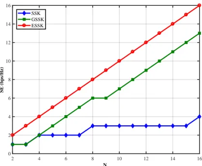
2.1 Time, frequency and space multiplexing . . . 10 2.2 MIMO transmission system . . . 13 2.3 SSK concept illustration . . . 16 2.4 Spatial Modulation Concept illustration . . . 16 2.5 Spatial Modulation Block Diagram . . . 17 2.6 Generalised Spatial Modulation . . . 20 2.7 Extended SSK concept . . . 21 2.8 SE of SSK, GSSK, and ESSK schemes in terms of the number of transmit
antennas. . . 22 2.9 Example of RASK System . . . 23 2.10 Receive Spatial Modulation transmission system . . . 24 2.11 MRT preprocessing illustration . . . 25 2.12 ZF preprocessing illustration . . . 26 2.13 Summary . . . 29
3.1 Example of RASK system with Nr =4 . . . 32 3.2 Block diagram of a RASK transmission chain . . . 33 3.3 NCML receiver with envelope detector . . . 39 3.4 BER performance of 16×4 and 16×8 ZF-RASK systems using CML and
NCML detectors over Rayleigh channel, simulated and theoretical results 42 3.5 Receiver with NRFRF chain and switch . . . 43 3.6 BER of 32×16 ZF-RASK using NCML or CML detection with a variable
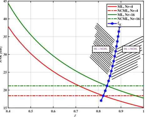
number of RF chains using switches . . . 44 3.7 The needed SNR to achieve a Bit Error Probability (BEP)=10−4for a
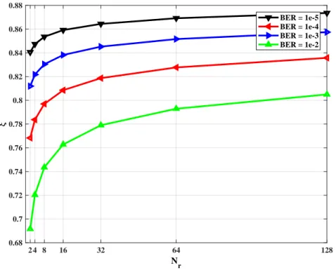
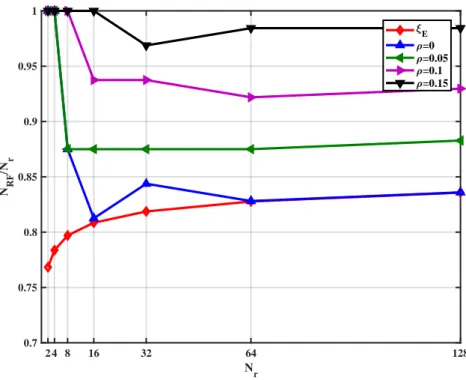
ZF-RASK system with Nr = 4 and Nr = 16 using CML and NCML detec-tion, in terms of ξ . . . . 45 3.8 Variation of ξEin terms of Nrfor ZF-RASK for different targeted BEP. . 46 3.9 Ratio of the number of RF chains for each receiver configuration of Nr
for ZF-RASK for different switching coefficients. . . 47 3.10 BER performance of 16×2 MRT-RASK systems using ML, MR and MP
detectors over Rayleigh channel, simulated and theoretical results . . . . 51 3.11 BER performance of 8×4 MRT-RASK systems using all detectors over
Rayleigh channel . . . 51 3.12 Block diagram of RASK . . . 52
xx LIST OF FIGURES
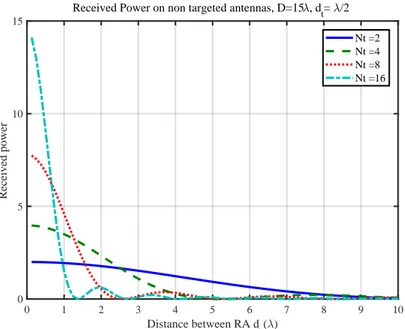
3.13 BER performance of a MIMO LoS MRT-RASK transmission system, for dr=λ, dt =λ/2 and D=15λ . . . 54
3.14 Received power on the non-targeted antenna in terms of the distance between receive antennas . . . 55 3.15 Received power on each antenna targeting R1(Left) and R2(right) . . . 56
4.1 Example of the Extended-RASK system with Nr=2 . . . 60 4.2 Block diagram of Extended-RASK . . . 61 4.3 ERASK performance using ML and PT detectors with Nt =8 -
Compar-ison of theoretical performance and simulation results . . . 66 4.4 Performance of ERASK with ML receiver - Nt=36. . . 66 4.5 Performance of conventional RASK with ML receiver - Nt=36. . . 67 4.6 Theoretical and simulation results comparison of BER vs SNR
perfor-mance of ERASK over uncorrelated Rayleigh fading channels. Nt = 8, Nr =2 and 4, σH=0 and 0.2 . . . 72 4.7 BER vs SNR performance of ERASK with Nt = 8 and Nr = 2 over
Rayleigh fading channels for perfect channel estimation and no corre-lation, and for σH= 0.2 with correlation factor ρ=0, 0.1, 0.5 and 0.9 . . . 72 4.8 BER vs SNR performance of ERASK over Rayleigh fading channels with
antenna correlation factor ρ = 0.1, Nt = 8 and 16, Nr = 2 and 4, σH= 0 and 0.2 . . . 73 4.9 BER performance of two MRT-ERASK over Rayleigh fading channel,
Nt= 32, Nr=2 and 4, simulation and theoretical results . . . 76 4.10 Comparison of the BER performance of two MRT-ERASK over a Rayleigh
fading channel, Nr=2 and 4 . . . 77 4.11 Comparison of the BER performance of MRT-ERASK and ZF-ERASK
over a Rayleigh fading channel, Nr=2 . . . 77 4.12 Illustration of ERSM concept . . . 78 4.13 Block diagram of ERSM system . . . 79 4.14 BER vs power ratio γ for a 8×2 MIMO with ERSM QPSK, 8-PSK and
16-PSK . . . 83 4.15 Theoretical and Simulation BER results for 8×2 and 8×4 ERSM with
QPSK and 8-PSK, with Rayleigh fading. . . 84 4.16 BER vs SNR for a 8×2 and 8×4 MIMO ERSM, for QPSK, 8-PSK, and
16-PSK with Rayleigh fading . . . 84
5.1 Example of the Extended-SSK system with Nt=2 for uplink transmission 88 5.2 Block Diagram for Extended-SSK . . . 89 5.3 BER performance of 4x8 ESSK system, using ML and EQ-ML detection,
theoretical and simulation comparison . . . 94 5.4 BER performance of 2x8 ESSK system, using ML and EQ-ML detection,
theoretical and simulation comparison . . . 95 5.6 Visualization of the transmission between Base Station and Connected
Device . . . 96
6.1 Block diagram of RASK with mmWave hybrid beamforming architecture 102 6.2 Channel illustration based on geometric model . . . 102
LIST OF FIGURES xxi
6.3 Illustration of the correlation minimization approach adopted for the RASK mmWave framework for two paths . . . 107 6.4 Illustration of the correlation minimization approach adopted for the
RASK mmWave framework for multiple receive antennas . . . 111 6.5 SE versus the ULA transmit array orientation for a given scenario (Nr =
2, SNR=10dB, dr=18λ, D=5000λ) in pure LoS environment . . . 112 6.6 SE versus the ULA transmit array orientation for a given scenario (Nr =
2, SNR=10dB, Nt =32, D=5000λ) in pure LoS environment . . . 113 6.7 SE versus the ULA transmit array orientation for a given scenario (SNR=
10dB, Nt=32, D=500λ, dr=25λ) in pure LoS environment . . . 114 6.8 Illustration of the effect of applying analog and hybrid beamforming for
the RASK mmWave framework in pure LoS environment with transmit ULA for a given scenario (Nt =128, Nr =2, dr=25λ, D=5000λ) . . . . 114 6.9 Illustration of the effect of applying analog and hybrid beamforming for
the RASK mmWave framework in pure LoS environment with transmit ULA for a given scenario (Nt = 128, Nr = 2, dr = 25λ, D = 5000λ) after applying the transmitter deployment optimization for correlation minimization as illustrated in Figure 6.3 . . . 115 6.10 Theoretical and numerical SE versus SNR for a given scenario (Nr =
2, dr = 18λ, D = 5000λ) in a pure LoS environment and in a sparse multipath environment (Np=6 paths) . . . 115 6.11 Theoretical and numerical ABER versus SNR for a given scenario (Nr =
2, dr = 10λ, D = 5000λ) in a pure LoS environment and in a sparse multipath environment (Np=6 paths) . . . 116 6.12 Theoretical ABER versus SNR for different scenarios (given D=5000λ)
List of Tables
2.1 GSM Mapping Table for Nt=5 and Na=2 . . . 20
3.1 Mapping table of the spatial symbol for a 4 receive antenna RASK . . . 32 3.2 Complexity of the transmitter and different receivers for RASK with ZF
and MRT precoding . . . 52 3.3 Testbed and theoretical SIR and BER results of a 4x2 MIMO LOS channel
with ν=2.4 GHz, D=15λ, dr=λ/4 and dt=λ/2. . . 56
4.1 The number of receive antenna needed for RASK and ERASK systems to acheive certain SE . . . 67
5.1 Operations needed at the base station and the connected device for Up-link and Down-Up-link . . . 96
6.1 Simulation Parameters . . . 112
Notations
Nomenclature
• A : matrix • a : vector • ai: i−th element of a • a : scalarOperators
• Q(.): Gaussian distribution function • [A]H: Trans-conjugate of the matrix A • [A]T : Transpose of the matrix A • [A]∗: Conjugate of the matrix A • Tr[A]: Trace of the matrix A • Ek : Expectation over k • dae: Ceil of a • bac: Floor of a • <{.}: Real part • ={.}: Imaginary part • Arg : Argument • det(.) : determinant
• CN (., .): Complex Gaussian distribution
• d(xk, xj): Hamming distance between xk and xj xxv
xxvi Notations
Symbols
• m : number of bits per symbol • k : index of targeted antenna • f : normalization factor
• M : order of M-order modulation • I : number of paths
• γ : Power Ratio • ¯τ : Switching factor • Es: Symbol energy
• Nr: Number of receive antennas • Nt: Number of transmit antennas
• Na: Number of active or targeted antennas • NS: Number of switches
• NRF : Number of RF chains • σn: standard deviation of noise
• σH : standard deviation of channel estimation error • σl : standard deviation of interference
• C: capacity
• Pt: total transmit power
• Pk: Power allocation vector to send the k-th spatial symbol
• pi,k : power allocation level to the i-th receive antenna when the k-th symbol is transmitted
• ¯Λ : transmit spatial correlation
• dt: inter-element antenna spacing at the transmitter • dr: inter-element antenna spacing at the receiver • D : Distance between the transmitter and the receiver • Ds: Symbol rate
• B : Bandwidth
Notations xxvii
• Rj: j-th receive antenna
• hj,i: complex channel coefficient
• wj,i: complex precoding matrix coefficient • λj: j-th eigenvalue of the channel matrix • λH
j : j-th eigenvalue of the channel matrix H • λHe
j : j-th eigenvalue of the equivalent channel matrix He • λmax: the maximum eigenvalue of the channel matrix • λw: the wavelength
• yj: The received baseband signal at the j-th receive antenna • r : The received baseband signal in SISO
• αi: complex gain associated with the i-th path in SISO
• αk,i : complex gain associated with the i-th path received by the k-th receive an-tenna
• ηj : complex Gaussian noise at receive antenna j
• θk,p: angle of departure for path p of receive antenna Rk • ∆θ : angular difference between two paths
• ρ : received SNR
• ρt: transmit spatial correlation factor • ρr: receive spatial correlation factor • φ : phase of received signal
• ν : Detection threshold • Pe: Binary error probability
• P (x): Probability of x
• s : The transmitted baseband signal • z : vector of equalized received signal
• sk : The transmitted baseband signal when sending k-th spatial symbol • y : The receive baseband signal vector
• x : symbol vector
xxviii Notations
• hk: channel vector associated to the k-th receive antenna
• fk : Analog beamforming vector associated to the k-th receive antenna • fLoS: Analog LoS beamforming vector
• fEGT: Analog Equal Gain Transmission beamforming vector • n : complex Gaussian noise vector
• at: transmit array steering vector • H : MIMO baseband channel matrix
• ¯H: average long term CSI that is accuratly estimated at the transmitter • ˜H: instantaneous CSI deviation matrix
• HI : Channel matrix with independent entries • Rt: transmit spatial correlation matrix
• Rr: receive spatial correlation matrix
• He: MIMO baseband equivalent channel matrix after analog beamforming • P : MIMO hybrid beamforming matrix
• W : MIMO baseband precoding matrix • FRF : analog beamformer
• INr : Nr×Nridentity matrix
• U : unitary matrix for SVD precoding in channel H • V : unitary matrix for SVD postcoding in channel H
• Λ : Diagonal matrix of eigenvalues of the channel matrix H • Ue: unitary matrix for SVD precoding in equivalent channel He • Ve: unitary matrix for SVD postcoding in equivalent channel He
List of Abreviations
• 2G : Second Generation of cellular network • 3G : Third Generation of cellular network • 4G : Fourth Generation of cellular network • 5G : Fifth Generation of cellular network • ABEP : Average Bit Error Probability • AM : Amplitude Modulation
• AoD : Angle of Departure
• AWGN : additive white Gaussian noise • BB : Base Band
• BEP : Bit Error Probability • BER : Bit Error Rate
• BIM : Beam Index Modulation • BS : Base Station
• CD : Connected Device
• CDMA : Code-Division Multiple Access • CSI : Channel State Information
• CSIR : Channel State Information at the Receiver • CSIT : Channel State Information at the Transmitter • DFT : Discrete Fourier Transform
• EE : Energy Efficiency
• EGT : Equal Gain Transmission
• ERASK : Extended Receive Antenna Shift Keying xxix
xxx List of Abreviations
• ERSM : Extended Receive Spatial Modulation • ESNR : Effective Signal to Noise Ratio
• ESSK : Extended Space Shift Keying • FDM : Frequency-division multiplexing • FDMA : Frequency-Division Multiple Access • FFT: Fast Fourier Transform
• FM : Frequency Modulation
• GPSM : Generalised Precoding Spatial Modulation • GRASK : Generalised Receive Antenna Shift Keying • GSM : Generalised Spatial Modulation
• GSSK : Generalised Space Shift Keying • IAI : Inter-Antenna Interference
• ICI : Inter-Carrier Interference
• IMT-A : International Mobile Telecommunications-Advanced • IoT : Internet-of-Things
• ISI : Inter-Symbol Interference • LoS : Line of Sight
• LTE : Long-Term Evolution
• MIMO : Multiple-Input Multiple-Output • MISO : Multiple-Input Single-Output • ML : Maximum Likelihood
• MMSE : Minimum Mean Square Error • mmWave : Millimeter Wave
• MRC : Maximum Ratio Combining
• MRMI : Maximum Real Minimum Imaginary • MRT : Maximum Ratio Transmission
• MTs : Mobile Terminals • MU : Multiuser
List of Abreviations xxxi
• OFDM : Orthogonal Frequency-Division Multiplexing • PEP : Pairwise Error Probability
• PSK : Phase Shift Keying • PT : Power Threshold
• RASK : Receive Antenna Shift Keying • RAT : Real Amplitude Threshold • RF : Radio Frequency
• RSM : Receive Spatial Modulation • SDM : Space-division multiplexing • SDMA : Space-Division Multiple Access • SE : Spectral Efficiency
• SEP : Symbol Error Probability • SER : Symbol Error Rate
• SISO : Single-Input Single-Output • SM : Spatial Modulation
• SMX : Spatial Multiplexing • SNR : Signal to Noise Ratio • SSK : Space Shift Keying
• STBC : Space-Time Bloc Coding • STC : Space-Time Coding
• SVD : Singular Value Decomposition • TDD : Time-Division Duplexing • TDM : Time-Division Multiplexing • TDMA : Time-Division Multiple Access
• TPSM : Transmit Precoding Spatial Modulation • TR : Time Reversal
• TSM : Transmit Spatial Modulation • ULA : Uniform Linear Array • ZF : Zero-Forcing
Chapter 1
General Introduction
1.1
Introduction
Passing from Base Band (BB) communication to higher frequency modulated signals, was the first major evolution in wireless communications in 1933. The reason was to avoid the interference and band limitation when multiple ends to end communications are implemented. Each user can have its own frequency band. In the Second Gener-ation of cellular network (2G), one of the main difference was the use of digital com-munication in 1991. This evolution enables the transmission of data services such as text messages and pictures, as well as the digital encryption. The Code-Division Multi-ple Access (CDMA) and Time-Division MultiMulti-ple Access (TDMA) are used to multiMulti-plex signals of different users. In the Third Generation of cellular network (3G), released in 2001, the wireless mobile network has transformed from a pure telephony system to a network that can transport rich multimedia contents. Especially for data services, the aim of 3G is to accommodate high data rate demanding applications such as mobile and fixed Internet access, video calls, and mobile television. Also, TDMA and CDMA are still used for user multiplexing in 3G, in addition to Frequency-Division Multiple Access (FDMA) and Orthogonal Frequency-Division Multiple Access (OFDMA).
In the Fourth Generation of cellular network (4G), the wireless systems were de-signed to fulfill the requirements of International Mobile Telecommunications-Advanced (IMT-A) using IP for all services [11]. The adopted system for the 4G is the Long-Term Evolution (LTE) and its extension, LTE-Advanced systems, with an advanced radio in-terface, OFDM, MIMO, and link adaptation technologies. The 4G architectures offer, in addition to the existing voice and data applications of 3G, ultra-broadband Internet ac-cess. In this way, high data rate demanding applications are provided, such as gaming, high-definition television, and cloud computing.
However, there is still a dramatic increase in the number of users who subscribe to mobile broadband systems every year. More and more people crave faster Internet access on the move, trendier mobiles, and, in general, instant communication with others or access to information. More powerful smartphones and laptops are becoming more popular nowadays, demanding advanced multimedia capabilities.
On the other hand, 4G networks have just about reached the theoretical limit on the data rate with current technologies and therefore are not sufficient to accommodate the above challenges. The Fifth Generation of cellular network (5G) network is expected
2 CHAPTER 1. GENERAL INTRODUCTION
Figure 1.1 – Evolution of cellular networks generations
to be standardized around 2020, and regarding the huge demand of data transmission between a large number of connected devices, it is widely agreed that compared to the 4G network, the 5G network should achieve 1000 times the system capacity, 10 times the spectral efficiency, energy efficiency and data rate, and 25 times the average cell throughput [1]. The aim is to connect the entire world, and achieve seamless and ubiq-uitous communications between anybody (people to people), anything (people to ma-chine, machine to machine), wherever they are (anywhere), whenever they need (any-time), by whatever electronic devices/services/networks they wish (anyhow). Figure 1.1 shows a part of the evolution of services provided by different cellular network gen-eration. One big challenge of the next 5G is then to accommodate the future cellular network with massive data traffic issued from machine type communication.
Internet-of-Things (IoT) is the keyword that represents the evolution in 5G that is able to connect the so-called Connected Device (CD) to the network. It is expected that those CD are adapted and enabled with autonomous behavior, and secure inter-connection, to achieve the higher degree of smartness making a full interoperability.
Moreover, things composing the IoT will be characterized by low resources in terms of both computation and energy capacity [2]. Accordingly, it is important to pay atten-tion to the complexity of operaatten-tions that are making the transmission between the CD and the network.
As result, increasing the data rate and the Spectral Efficiency (SE), whilst minimiz-ing energy consumption, are some of the key elements that drive research for designminimiz-ing future wireless communication systems.
The high costs for radio spectrum, on the one hand, and the bandwidth-consuming by services that need high data rate, on the other hand, require research in techniques that improve the SE considerably. Therefore, in recent years, the exploitation of the spatial dimension (multiple antennas at the receiver and/or multiple antennas at the transmitter) in radio systems have been subject to investigation by many researchers [12].
MIMO systems consist of multiple antennas at both the transmitter and/or receiver. By adding multiple antennas, a greater degree of freedom (in addition to time and fre-quency dimensions) in wireless channels can be offered to accommodate more infor-mation data. Hence, a significant performance improvement can be obtained in terms of reliability, SE, and Energy Efficiency (EE). In massive MIMO systems, the transmitter
1.2. CONTRIBUTIONS 3
and/or receiver are equipped with a large number of antenna elements (typically tens or even hundreds). The enormous number of receive antennas can be possessed by one device or distributed to many devices. Besides inheriting the benefits of conventional MIMO systems, a massive MIMO system can also significantly enhance both SE and EE. Furthermore, in massive MIMO systems, the effects of noise and fast fading vanish, and intracell interference can be mitigated using simple linear precoding and detection methods.
Since the early 2000s, SM has established itself as a promising transmission concept for low complexity devices and low power consumption [2]. SM exploits the index of transmit antenna or receive antennas to transmit additional information bits commonly referred to as spatial bits and spatial symbols [3]–[6].
The first proposed SM schemes concerned open loop systems because they required no Channel State Information at the Transmitter (CSIT). They are called Transmit Spa-tial Modulation (TSM) schemes and mainly relies on Space Shift Keying (SSK) strate-gies [7]. This technique could be used for uplink transmission because of its simplicity and offers a good SE compared to the other SISO transmission schemes. On the other side, when MIMO system has more transmit antennas than receive antennas, just like the downlink transmission between Base Station (BS) and the user, then, its capacity when operated under the CSIT mode may be much higher than that when operated under the Channel State Information at the Receiver (CSIR) mode [13]. For this reason, SM principles can be transposed at the receiver side, leading to the RSM concept. As introduced in [8], RSM can also be referred to as TPSM since it relies on a preprocessing or spatial pre-coding operation that exploits the CSIT, so as to target one of the anten-nas of the receiver. Hence, in contrast to TSM, which uses the SSK concept to map the information bits to the transmit antenna indices, RSM carries out a kind of pre-SSK op-eration to map them to the indices of the receive antenna. A very simple detection is needed at the receiver to detect the spatial symbol [9], [10]. Inspired by this technology, the project "Space Modulation" is launched by the National Research Agency (ANR) whose objective is "to design a new air interface for mobile Internet-of-the-objects to be integrated into future air interfaces for networks mobiles (5G) and WLANs". This thesis, which is part of this project, takes into account one of the signal processing part, and studied the performance of SM schemes at the transmitter and receiver side, that could offer a complete uplink and downlink transmission system between the BS and CD that provide a low computation complexity at the CD while it is maintained at the BS, with good SE.
1.2
Contributions
Different contributions have been made in this thesis in order to evaluate the perfor-mance of the SM to be used for low complexity devices in uplink and downlink trans-mission. In general, We focused on the performance of different schemes with different detection algorithms, and in multiple channel scenarios. The computational complex-ity has been also taken into account.
In the first contribution, we started with the SM at the receiver, with an existing scheme called RASK to be evaluated. Here, the transmitter performs a preprocessing step to target one receive antennas, resulting in an SE equal to log2(Nr). Two precoding
4 CHAPTER 1. GENERAL INTRODUCTION
methods are used and compared in our framework that is ZF and MRT. At the receiver side, different detection schemes are proposed, for each precoding method, and could be categorized into two categories: coherent and non-coherent detection. The first one estimates the signal and its phase, and so a phase synchronization between antennas is needed, while the second one only estimates the received power. We derived the theo-retical BEP conditioned by the channel for some detectors, to evaluate its performance. For ZF RASK, we demonstrated analytically that the optimal receiver can be reduced to a single tap detector, because of the interference cancellation. Also, results show that the coherent detection has better performance but in the cost of additional hardware complexity at the receiver, since a down converter is needed for each receive antenna. In order to reduce the hardware complexity of the coherent detector, we proposed to use switches at the receiver, so that multiple receive antenna are connected to one RF chain. This method leads to a degradation in the effective SNR, and so a degradation in performance. Thus, depending on the ratio of the number of RF chain to the number of the receive antenna, the non-coherent detector could outperform the coherent detector when switches are used. So, we calculated the equivalence point that gives the mini-mum number of RF chains needed so that the coherent detector stay more performante than the non-coherent one. For MRT RASK, the ML detector remains more complex and needs channel estimation. We proposed different detectors for MRT RASK that doesn’t need channel estimation. The computation complexity was studied and com-pared, and analytical derivations the theoretical BEP for some detectors was provided and validated through simulations. Finally, the RASK scheme with MRT precoding was analytically studied under LOS channel scenario. Results were validated through simulations and practical implementation.
In the second contribution, we proposed to increase the SE of the RASK, so instead of targetting one receive antenna, a variable number of receive antenna are targeted each symbol duration. This novel scheme is called ERASK. First, we presented the concept of the scheme, when the ZF precoding is used. We demonstrated that the ML detector is reduced to an amplitude threshold detector. With the ML, another detector that is based on a power threshold was also presented. The analytical derivations of the BEP for the two detectors are provided and validated through simulations. After-ward, we studied the effect of error in channel estimation and the correlation between antennas on the performance of ZF ERASK, by analytical derivations of the BEP and simulations. Moreover, the studied the performance of the ERASK when the MRT pre-coding is used, to be compared with the ZF ERASK. Here, the amplitude threshold is no more the optimal detector, and results show that the ZF ERASK outperforms the MRT ERASK when the same detector is used. Also, it is showed that the more the num-ber of transmit antennas is, the closer the performance of MRT ERASK to ZF ERASK is. Finally, we proposed to transmit additional IQ symbools with the spatial symbol of ERASK, called ERSM. But since ERASK use all possible combinations of targetting antennas, and one of them is to not targetting any receive antenna, in this case, it is im-possible to send the IQ symbol. So we proposed to use two power levels to transmit the two symbols (spatial and IQ symbols). we derived also the analytical performance of the BEP. An optimal power ratio between the two power levels that minimize the total BEP, was derived analytically and validated by simulations. Results show that when the optimal ratio is used, the performance of ERSM remains the same if we change the configuration of the symbol, by changing the order of IQ modulation or the number of
1.3. THESIS OUTLINE 5
targeted receive antennas, but keeping the same SE.
In the third contribution, we proposed an analog scheme to ERASK at the transmit-ter for the uplink transmission, called ESSK. A variable number of transmit antennas is activated in order to increase the overall SE. We studied the performance of the scheme in Rayleigh channel by deriving the analytical BEP when ML detector is used. Also, we proposed to implement an equalization at the receiver to detect the symbol, by us-ing the same matrix of precodus-ing in the downlink transmission for ERASK. The result shows that ML detector outperforms the equalized detector, but the more the number of receive antennas, the closer the performance of equalized detector to the ML is. Fi-nally, we proofed the duality of ESSK and ERASK in uplink and downlink, when the equalized detector is used.
In the fourth and last contribution, a detailed study for RASK in mmWave systems was given, covering all possible scenarios analytically, and numerically compared to the existing work in the literature. We proposed to use hybrid beamformer with ana-log and digital beamformer. In anaana-log beamformer, LoS beamsteering and EGT beam-forming method where proposed and studied, while the digital precoder is always the ZF precoder. We derived closed-form solutions for the SE in case of pure LoS channel environments for any possible deployment scenario, given that two receive antennas exist, and optimal transmit array deployment optimization is applied for correlation minimization. Similarly, we derived closed-form solutions for the BEP in case of pure LoS channel environments for any possible deployment scenario, given that two re-ceive antennas exist, and optimal transmit array deployment is applied for correlation minimization. Moreover, a closed form solution for the BEP was derived for sparse multipath environments as well to have a complete analysis for the achievable perfor-mance of the RASK in mmWave systems. All the introduced models were validated with numerical analysis.
1.3
Thesis Outline
In this section, we will give the outline of this thesis. In Chapter 2, a brief history of the evolution of wireless communication is provided. It is explained why the exploita-tion of the spatial dimension to enhance the performance of wireless systems leads the researches to be interested in MIMO communication systems during the last decades. The concept of MIMO systems and its advantages are presented. Afterward, because of the trade-off diversity-multiplexing gain, the concept SM scheme is presented, and it is explained why SM provide an energy efficient transmission because of the exploita-tion of both diversity and multiplexing gain. Thus, the state of art of SM was given in two part. The first one talk about the transmit SM, where the concept of SM with or without additional IQ symbols is presented, as well as the block diagram, with an overview on different schemes that are based on this concept with their performance studies. Advantages and disadvantages of SM were also provided in this chapter. In the second part, the receive SM is presented, with different precoding methods. Also, as for transmit SM, an overview of the published research of different schemes that are based on receive SM concept are provided.
In Chapter 3, the RASK scheme is studied using ZF and MRT precoding. Different detection scheme associated with each precoding method are provided. Performance
6 CHAPTER 1. GENERAL INTRODUCTION
analysis of the BEP is provided for some detectors, and confirmed by simulations. The computational complexity was also studied to classify different detectors. We also pro-posed to use switches at the receiver in order to reduce the hardware complexity when a coherent detector is used. Analytical derivations showed that for ZF RASK, the ML detector could be reduced to a Single Tap detector. Also, it is shown that the coherent detection has lower BER than the non-coherent, but when switches are used for the co-herent detector, its performance degrades. Finally, the performance of MRT RASK was analytically studied under LOS channel scenario and validated through simulations and practical implementation.
In Chapter 4, the novel scheme ERASK that was proposed to improve the SE of spa-tial modulation at the receiver side to Nr, by allowing a transmission towards a vari-able number of receive antennas simultaneously, was presented. It is demonstrated that when the ZF precoding is used, the ML detection is reduced to a simple ampli-tude threshold. A power threshold detector was also presented with the ML. The ex-pected theoretical performance of the two detectors is provided. Also, the effect of error in channel estimation and the effect of correlation between antenna where stud-ied. In addition, the ERASK with MRT precoding was presented and compared to the ZF ERASK. Finally, the ERSM scheme, that allows the transmission of ERASK and IQ symbols simultaneously, was studied, and the optimal ratio of power levels was calcu-lated, to give the better performance.
In Chapter 5, the novel scheme Extended Space Shift Keying (ESSK) that is analog to the ERASK at the transmitter for the uplink transmission of a device connected to a base station was presented. It is demonstrated how the ESSK provides an SE equal to Nt, which is the number of receive antennas in downlink when ERASK is implemented. Two detection strategies are presented, the ML detector and the ZF equalized ML. The-oretical performance of the two detectors is provided. Results show that the ML detec-tor outperforms the equalized detecdetec-tor, but the more the number of transmit antennas increases, the smaller the difference in performance is. Thus, we demonstrated the duality in performance between ERASK, and ESSK such that the equalized detector is implemented. Finally, an Uplink and Downlink transmission system between a base station and a connected device based on the extended SM has been proposed, and we showed how the computational complexity is reduced at the connected device.
In Chapter 6, a novel framework considering the RASK technique with hybrid beamforming in a Millimeter Wave (mmWave) propagation environment is presented. The channel model was described, followed by the beamforming strategies, where a combination of analog beamforming and digital precoding is performed. A closed-form solution for the SE in case of pure LoS channel environments for any possible de-ployment scenario is derived, given that two receive antennas exist, and optimal trans-mit array deployment optimization is applied for correlation minimization. Moreover, the BEP performance of the framework is analytically and numerically studied with a maximum likelihood detector. All the theoretical and numerical analyses are done for the pure Line of Sight (LoS) channel environment and sparse multi-path channels in order to fully characterize high-frequency environments such as mmWave systems. All the introduced models were validated with numerical analysis.
Finally, in Chapter 7, summury of all contributions in this thesis with results is provided. We presented also some propositions to be provided in future works.
1.4. LIST OF PUBLICATIONS 7
1.4
List of Publications
Journal Paper1. A. Mokh, M. Crussiere, M. Helard, and M. D. Renzo, “Theoreticalperformance of coherent and incoherent detection for zero-forcingreceive antenna shift key-ing”,IEEE Access, 2018.
International Conferences
2. A. Mokh, Maryline Helard, and Matthieu Crussiere. "Space Shift Keying Modu-lations for Low Complexity Internet-of-Things Devices." GLOBECOM 2017-2017 IEEE Global Communications Conference. IEEE, 2017.
3. A. Mokh, Maryline Hélard, and Matthieu Crussiere. "Extended Receive Spatial Modulation MIMO scheme for Higher Spectral Efficiency." 2018 IEEE 87th Vehic-ular Technology Conference. 2018.
4. A. Mokh, Matthieu Crussière, and Maryline Hélard. "Performance analysis of extended RASK under imperfect channel estimation and antenna correlation." Wireless Communications and Networking Conference (WCNC), 2018 IEEE. IEEE, 2018.
5. A. Mokh, Maryline Hélard, and Matthieu Crussière. "Extended receive antenna shift keying." International Conference on Telecommunications. 2017.
6. A. Mokh, Matthieu Crussière, and Maryline Hélard. "Performance analysis of the maximum ratio transmission preprocessing for extended receive antenna shift keying." Wireless Personal Multimedia Communications (WPMC), 2017 20th In-ternational Symposium on. IEEE, 2017.
7. A. Mokh, Y. Kokar, M. Hélard et M. Crussière, Time reversal receive antenna shift keying on MIMO LOS channel, Sensors Networks Smart and Emerging Technolo-gies (SENSET), 2017.
Patents
8. A. Mokh, M. Hélard, M. Crussière, Y. Kokar, J.-C. Prévotet, Technique de mod-ulation spatiale et dispositif de réception associé, déposé le 5 février 2016, FR 3047621. Ext. PCT WO2017134403 le 10/08/2017.
9. A. Mokh, M. Hélard, M. Crussière, Y. Kokar, J.-C. Prévotet, Technique de modu-lation spatiale, déposé le 13 septembre 2016, FR16/01344.
10. A. Mokh, M. Hélard, M. Diallo, Methode de transmission sans fil et dispositif associé, déposée le 01 octobre 2018, FR18/01026.