ةيبعشلا ةيطارقيمدلا ةيرئازلجا ةيروهملجا
République Algérienne Démocratique et Populaire
يملعلا ثحبلاو لياعلا ميلعتلا ةرازو
Ministère de L'enseignement Supérieur et de La Recherche Scientifique
يعمالجا زكرلما
بيعشوب جاحلب
تنشوتم ينع
Centre Universitaire Belhadj Bouchaib-Ain Témouchent
Institut de Technologie Departement de Genie Mécanique Laboratoire des Structures Intelligentes
THESE
Présentée pour l’obtention du diplôme de DOCTORAT 3
emeCycle
Domaine : Science et Technologie
Filière : Génie Mécanique
Spécialité : Energétique
Par : El MERIAH Abderrahmane
Intitulé de la thèse
Etude thermo hydraulique d’un écoulement à
moyenne température
Soutenue publiquement, le / / , devant le jury composé de :
Mr. ZIADI Abdelkader Pr Président Centre Universitaire BELHADJ Bouchaib/ Ain
Témouchent.
Mr. ADJLOUT Lhouari Pr Examinateur Université des Sciences et de la Technologie Mohamed Boudiaf - Oran
Mr. IMINE Bachir Pr Examinateur Université des Sciences et de la Technologie Mohamed Boudiaf - Oran
Mme. BENSAAD Bourassia MCA Examinateur Centre Universitaire BELHADJ Bouchaib/ Ain Témouchent.
Mr. NEHARI Driss Pr Directeur de thèse Centre Universitaire BELHADJ Bouchaib/ Ain Témouchent.
Mr. HAMMADI Larbi MCA Co-Directeur Université des Sciences et de la Technologie Mohamed Boudiaf - Oran
ةيبعشلا ةيطارقيمدلا ةيرئازلجا ةيروهملجا
People's Democratic Republic of Algeria
يملعلا ثحبلاو لياعلا ميلعتلا ةرازو
Ministry of Higher Education and Scientific Research
تنشوتم ينع
بيعشوب جاحلب
يعمالجا زكرلما
University Center of Belhadj Bouchaib-Ain Temouchent
Institute of Technology
Departement of Mechanical engineering Smart Structures Laboratory
THESIS
Presented for graduation in DOCTORATE 3
rdCycle
Domain: Science and Technology
Field : Mechanical Engineering
Speciality : Energetic
By : EL MERIAH Abderrahmane
Title of the thesis
Thermo-hydraulic study of a flow at medium
temperature
Publicly supported, in / / , before the jury composed of:
Mr. ZIADI Abdelkader Pr President University Center of BELHADJ Bouchaib/
Ain Témouchent.
Mr. ADJLOUT Lhouari Pr Examiner University of Sciences and Technology Mohamed Boudiaf - Oran
Mr. IMINE Bachir Pr Examiner University of Sciences and Technology Mohamed Boudiaf - Oran
Mrs. BENSAAD Bourassia MCA Examiner University Center of BELHADJ Bouchaib/ Ain Témouchent.
Mr. NEHARI Driss Pr Director of thesis University Center of BELHADJ Bouchaib/ Ain Témouchent.
Mr. HAMMADI Larbi MCA Co-Director University of Sciences and Technology Mohamed Boudiaf - Oran
I would to direct my special thank to the crew of jury
Mr. Abdelkader ZIADI,
Mr. Lhouari ADJLOUT, Mr. Bachir IMINE and Mrs. Bourassia BENSAAD
for their participation in this scientific session and taking it into account.
Also I want to thank my supervisor Mr.Pr Driss Nehari for the efforts
which has made for us throughout my PhD cycle.
Without forget Mr.Pr Abdelkader Ziadi, Mr. Dr Larbi Hammadi and Mrs.
Bourassia BENSAAD to the helps that has been given to us.
My thanks and appreciation to all teachers in the Mechanical
Engineering Department and fellow coworkers in the Smart Structure
Laboratory.
To all the academic promotions of Mechanical Engineering.
Dedication
First, I thank Allah Almighty who lights us the right way.
I would like to thank everyone who made this possible degree. I would like to
acknowledge my family and parents; specially to my mother, i want to express my
appreciation for your love and support.
Without forget my PhD students friends and brothers Remlaoui ahmed, Saadaoui
yacine and Ikbel ayat yala.
Finally, to all my teachers who taught me to know myself along my university
studies ... Thank you.
I
Abstract
This work focuses on the thermal energy storage utilization using latent heat transfer mode, different thermo physical characteristics of phase change materials (PCMs) have been discussed by their applications. A heat transfer evaluation of a shell and tube thermal energy storage (TES) unit has been carried out numerically. This devise is filled by organic material (paraffin wax) which is considered as a phase change material (PCM). Distilled water plays a role of heat transfer fluid (HTF) that flows inside the tube by constant inlet temperatures at melting and solidification moment of PCM. All the system storage is thermally isolated with the external environment. The enthalpy formulation is used to analyze the heat transfer inside 2D planar physical model during phase change process. As a result, a good agreement is found compared to the experimental results of the literature. First, the effect of geometrical parameters (tube length and shell diameter) and Reynolds number on the charging and discharging time in terms of HTF outlet temperature are investigated. The obtained results reveal that the tube length and the shell diameter are among the most influential geometrical parameters on the melting and solidification time, similarly the Reynolds number has too much effect to speed up the charging cycle. Moreover, an improved thermal storage unit is proposed which contains two phase change materials (PCMs), separated longitudinally inward the shell space and have a close melting point and different thermal characteristics. This configuration is more stable and speeds up the charging and discharging processes compared to the first unit. In addition to that, several unit positions were examined to interpret physically the thermal demeanor of the fusion process in terms of; heat transfer modes estimation, PCM melting rate, axial and radial temperatures distribution. The obtained results clarify that the TES unit inclination according to the range angles [0-90°] makes an imbalance of the natural convection in the PCM liquid fraction which contributes to create an instability and diminution of the heat transfer during the melting process. Moreover, the vertical unit state was the favorite position to the heat transfer recirculation inward the PCM.
II
ّ خلملا
ص
از٘ ّؼٌا ً ٠ ضوش ٍٝػ َاذخزسا ٓ٠ضخر خلبطٌا خ٠ساشسٌا َاذخزسبث ةٍٛسأ ًمٔ حساشسٌا ِٕبىٌا خ ، ذلٚ ذّر خشلبِٕ صئبصخٌا خ١ئب٠ض١فٌا خ٠ساشسٌا فٍزخٌّ داِٛ زِ ش١غ ح سٛطٌا (PCMs) غِ بٙربم١جطر . ُر ءاشخإ ُ١١مر ّٟلس لا ٔز مب ي حساشسٌا ٟف حذزٚ ٓ٠ضخر خلبطٌا خ٠ساشسٌا (TES) ٌ فلاغٍ ةٛجٔلأاٚ . ُز٠ ءًِ ز٘ حذزٌٛا ٖ خطساٛث داٌّٛا خ٠ٛضؼٌا ( غّش ٓ١فاسبجٌا ) ٞزٌا شجزؼ٠ حدبِ ١غزِ ش ح سٛطٌا (PCM) ، تٔبدث ف هٌر ْأ ءبٌّا شطمٌّا تؼٍ٠ اًسٚد و ًئبس ًمٔ حساشسٌا (HTF) ٞزٌا كفذز٠ ًخاد ةٛجٔلأا ٓػ ك٠شط دبخسد حساشز يٛخذٌا خزثبثٌا ذٕػ خ١ٍّػ ْبثٚزٌا تٍصزٌاٚ PCM ، ُز٠ يضػ َبظٔ ٌا ٓ٠ضخز ب٠ساشز غِ خئ١جٌا خ١خسبخٌا . َذخزسر خغ١ص ٜٛزسٌّا ٞساشسٌا ً١ٍسزٌ يبمزٔا حساشسٌا ًخاد جرٌّٕٛا ٞدبٌّا ٞٛزسٌّا ٟئبٕث دبؼثلأا ءبٕثأ خ١ٍّػ ش١١غر سٛطٌا . خد١زٔٚ هٌزٌ ، ُر سٛثؼٌا ٍٝػ قبفرا ذ١خ خٔسبمِ غِ حئبزٌٕا خ١ج٠شدزٌا ةدلأٌ . ًلاٚأ ، ُر خساسد ش١ثأر دبٍّؼٌّا خ١سذٌٕٙا ( يٛط ةٛجٔلأا شطلٚ ٌا فلاغ ) ُلسٚ صذٌٕٛ٠س ٍٝػ ِٓص ٓسشٌا غ٠شفزٌاٚ خٌلاذث خخسد حساشز جشخِ HTF . شٙظر حئبزٌٕا ٟزٌا ُر يٛصسٌا بٙ١ٍػ ْأ يٛط ةٛجٔلأا شطلٚ ٌا فلاغ بّ٘ ِٓ ٓ١ث شثوأ دبٍّؼٌّا خ١سذٌٕٙا اًش١ثأر ٍٝػ ِٓص ْبثٚزٌا تٍصزٌاٚ ، ًثٌّبثٚ ْئف ُلس صذٌٕٛ٠س ٌٗ ش١ثأر ش١جو اًذخ ٍٝػ غ٠شسر حسٚد ٓسشٌا . حٚلاػ ٍٝػ ،هٌر ُر ذاشزلا حذزٚ ٓ٠ضخر خ٠ساشز خٕسسِ ٞٛزسر ٍٝػ ١ردبِ ٓ ١غزِ ش بر سٛطٌا PCMs ، ْلاٛصفِ بً١ٌٛط ٓػ خمطِٕ خفذصٌا ٌٙٚ ّ ب خطمٔ سبٙصٔا خج٠شل صئبصخٚ خ٠ساشز خفٍزخِ . از٘ ٓ٠ٛىزٌا شثوأ اًساشمزسا عشس٠ٚ دب١ٍّػ ٓسشٌا غ٠شفزٌاٚ ًخٔسبمِ حذزٌٛبث ٌٝٚلأا . خفبضلإبث ٌٝإ هٌر ، ُر صسف ذ٠ذؼٌا ِٓ غلاِٛ داذزٌٛا ش١سفزٌ نٍٛسٌا ٞساشسٌا خ١ٍّؼٌ جبِذٔلاا ِٓ ث١ز : ش٠ذمر دلاذؼِ ًمٔ حساشسٌا ، يذؼِ سبٙصٔا PCM ، غ٠صٛر دبخسد حساشسٌا خ٠سٛسٌّا خ١ػبؼشٌاٚ . رضٛر حئبزٌٕا ٟزٌا ُر يٛصسٌا بٙ١ٍػ ْأ ً١ِ حذزٚ TES بًمفٚ ب٠اٚضٌ قبطٌٕا [ 0 -00 ]° ٞدؤ٠ ٌٝإ يلازخا ْصاٛزٌا ٟف ًّسٌا ٞساشسٌا ٟؼ١جطٌا ٟف ءضخ ًئبسٌا PCM ٞزٌا ُ٘بس٠ ٟف كٍخ َذػ ساشمزسا صمٔٚ ٟف ًمٔ حساشسٌا ءبٕثأ خ١ٍّػ ْبثٚزٌا . حٚلاػ ٍٝػ هٌر ، ذٔبو ٌ خ٠دّٛؼٌا خ١ؼضٌٛا حذزٍٛ ٟ٘ خٔبىٌّا خٍضفٌّا حدبػلإ ش٠ٚذر حساشسٌا ث ًخاذ (PCM)Resumé
Ce travail se concentre sur l'utilisation du stockage de l'énergie thermique en utilisant le mode de transfert par chaleur latente, différentes caractéristiques thermo-physiques des matériaux à changement de phase (PCM) ont été discutées par leurs applications. Une évaluation du transfert de chaleur d'une unité de stockage d'énergie thermique (TES) à tube et calandre a été réalisée numériquement. Ce dispositif est rempli par une matière organique (paraffine) qui est considérée comme un matériau à changement de phase (PCM), ou l'eau distillée joue un rôle de fluide
III caloporteur (HTF) qui circule dans le tube par des températures d'admission constantes au moment de fusion et solidification de PCM, tout le stockage du système est isolé thermiquement avec l'environnement externe. La formulation d'enthalpie est utilisée pour analyser le transfert de chaleur à l'intérieur d’un modèle physique planaire 2D pendant le processus de changement de phase. En conséquence, un bon accord est trouvé par rapport aux résultats expérimentaux de la littérature. Tout d'abord, l'effet des paramètres géométriques (longueur du tube et diamètre de la coque) et le nombre de Reynolds sur le temps de charge et de décharge en termes de température de sortie HTF sont étudiés. Les résultats obtenus révèlent que la longueur du tube et le diamètre de la coque sont parmi les paramètres géométriques les plus influents au moment de la fusion et de la solidification, de même que le nombre de Reynolds a trop d'effet pour accélérer le cycle de charge. De plus, il est proposé une unité de stockage thermique améliorée qui contient deux matériaux à changement de phase (PCM), séparés longitudinalement vers l'intérieur de l'espace de la coquille et ayant un point de fusion proche et des caractéristiques thermiques différentes. Cette configuration est plus stable et accélère les processus de charge et de décharge par rapport à la première unité. En plus de cela, plusieurs positions unitaires ont été examinées pour interpréter physiquement le comportement thermique du processus de fusion en termes de; estimation des modes de transfert de chaleur, taux de fusion du PCM, distribution des températures axiale et radiale. Les résultats obtenus clarifient que l'inclinaison de l'unité TES selon les angles de plage [0-90°] crée un déséquilibre de la convection naturelle dans la fraction liquide PCM qui contribue à créer une instabilité et une diminution du transfert de chaleur pendant le processus de fusion. De plus, l'état de l'unité verticale était la position favorite pour la recirculation du transfert de chaleur vers l'intérieur du PCM.
IV
Contents
Acknowledgement Abstract ... I Contents...IV Nomenclature... VII List of Figures ... VIII List of Tables...XIGeneral Introduction ...1
Chapter 1: Thermal Ene rgy Storage (TES) Methods ...4
1.1 Introduction ...4
1.2 Thermal Energy Storage ...4
1.2.1 Sensible TES ...5
1.2.2 Latent TES ...6
1.2.2.1 Phase Change Materials (PCMs) ...7
1.2.2.2 Types of PCM ...8
1.2.2.2.1 Organic phase change materials ...9
1.2.2.2.2 Inorganic phase change materials ...9
1.2.2.2.3 Eutectics ...10
1.2.2.3 Difficulties with PCMs ...10
1.2.2.4 Applications of PCMs ...12
1.2.2.5 Characterization of PCMs ...13
1.2.2.6 Selection of PCMs for latent TES ...16
1.2.3 Thermo-chemical TES Units...17
1.2.3.1 Thermo-chemical Energy Storage Components and Processes ...18
.a Charging ...18
.b Storing ...18
.c Discharging ...18
V
Chapter 2: Literature survey ...20
2.1 Introduction ...20
2.2 Brief literature ...20
2.3 Conclusion ...33
Chapter 3: Mathematical and Numerical modeling ...34
3.1 Introduction ...34
3.2 Finite difference methods ...34
3.3 Finite element methods ...35
3.4 Finite volume methods ...35
3.5 Mathematical model...35
3.5.1 Governing equations...35
3.6 Boundary conditions ...36
3.7 Grid mesh ...37
3.8 Numerical solving ...39
3.8.1 The presentation of the computational code ...40
3.8.2 Preprocessor “GAMBIT” ...41
3.8.3 Solver “FLUENT” ...41
3.8.4 Post-processor “FLUENT” ...42
3.8.5 Method of solving transport equations ...42
3.8.5.1 Discritization scheme ...42
3.8.6 Segregated algorithms ...44
3.8.6.1 Choice of pressure-Speed Coupling Method ...44
3.8.6.2 SIMPLE Algorithm ...46
3.8.7 Numerical resolution ...46
3.8.7.1 Convergence control parameter ...46
3.8.7.2 Convergence criterion ...46
3.8.7.3 Under-relaxation ...47
3.9 Steps to solve the proble m ...47
Chapter 4: Results and Discussions ...48
VI
4.2 Section I : Effect of the physical and geometrical parame ters...48
4.2.1 Physical model ...48
4.2.2 Boundary conditions ...49
4.2.3 Grid mesh Independency ...50
4.2.4 Results and discussions ...51
4.2.4.1 Validation ...51
4.2.4.2 Parametric study ...52
4.2.4.2.1 Influence of tube length ...52
4.2.4.2.2 Effect of shell diameter ...53
4.2.4.2.3 Effect of Reynolds number ...54
4.2.4.2.4 Improvement of TES unit ...56
4.3 Section II : Effect of the unit inclination on the PCM thermal behaviors ...58
4.3.1 Physical model ...58
4.3.2 Boundary condion ...59
4.3.3 Grid mesh independacy ...60
4.3.4 Results and discussion ...61
4.3.4.1 Validation ...61
4.3.4.2 Parametric study ...62
4.3.4.2.1 Heat transfer modes Evaluation ...62
4.3.4.2.2 Effect of the unit inclination on the PCM melting front ...65
4.3.4.2.3 Effect of the unit inclination on the PCM temperatures distributions ...68
4.4 Conclusion...74
General conclusion ...75
VII
Nomenclature
Q : Heat flux J/s T : Temperature C° m : mass Kg Cp : Heat capacity J/Kg.K s : solid ---- l : liquid ---- dt : Temperature variation ---- ρ : density Kg/m3 : gravitational acceleration m/s2 k : thermal conductivity W/m.K µ : dynamic viscosity N.s/m2 or Kg/m.sSi & Sh : source terms ----
u : velocity m/s i : i-direction ---- j : j-direction ---- x : cartesian coordinate ---- h : specific enthalpy J/Kg hS : sensible enthalpy J/Kg H : total enthalpy J/Kg ΔH : enthalpy change J/Kg
href : reference enthalpy J/Kg
Tref : reference temperature C°
L : specific enthalpy J/Kg
γ : liquid fraction ----
ε : infinity avoidance constant ----
C : constant reflecting the morphology ----
: Physical properties of the fluid ----
P : pressure N/m2
VIII
List of Figures
Chapter 1
Fig 1.1 Linear relationship between energy stored and increased temperature ... 5
Fig 1.2. Schematic representation of phase change process (Socaciu 2012) ... 8
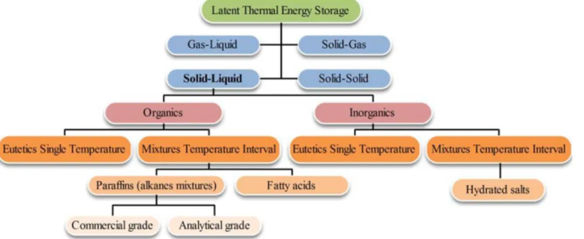
Fig 1.3 PCMs classifications (Ravikumar and Srinivasan 2008) ... 8
Fig 1.4 Methods of thermal energy storage: (a) sensible heat; (b) latent heat; (c) thermo-chemical reactions (de Gracia and Cabeza 2015). ... 17
Fig 1.5 Processes involved in a thermochemical energy storage cycle: charging, storing and discharging. (H Abedin and A Rosen 2011) ... 19
Chapter 2 Fig. 2.1 Shell and tube TES unit has two PCMs separated radially (Adine and El Qarnia 2009) ... 21
Fig 2.2 Dimensions (a) and actual photograph (b) of the LHTS unit without insulation(Wang et al. 2016b) ... 22
Fig 2.3 The shell and tube TES unit proposed in the literature (Mosaffa et al. 2012) ... 22
Fig 2.4 (d) Simple and (b,c) double TES unit HTF passage (Yang et al. 2016) ... 23
Fig 2.5 TES unit embedded by circular and longitudinal fins (Agyenim et al. 2009) ... 24
Fig 2.6 Shell and tube TES unit has two PCMs separated longitudinally (El Meriah et al. 2018) ... 24
Fig 2.7 inclined shell and tube TES unit (Kousha et al. 2017) ... 26
Fig 2.8 Physical configurations of different fins positions. (Al-Abidi et al. 2013) ... 28
Fig 2.9 Heat exchangers thermal energy storage units with (fins) direct contact (a), (b) and indirect heat exchange (c), (d) (Gasia et al. 2017) ... 29
Fig 2.10 Conical and cylindrical shell of TES unit (Akgün et al. 2007) ... 30
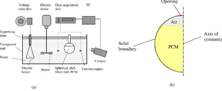
Fig 2.11 Spherical heat storage system in experimental (a) and numerical (b) study (Assis et al. 2007)... 31
IX Chapter 3
Fig. 3.1 Ansys Fluent steps simulation... 34
Fig 3.2 Boundary condition of the first study... 37
Fig 3.3 Boundary condition of the second study ... 37
Fig 3.4 Different typical grid ... 38
Fig 3.5 Basic interface of the code "FLUENT" ... 41
Fig 3.6 Control volume for the finite volume resolution ... 42
Fig 3.7 One-dimensional scheme illustrating an elementary volume surrounding a node P .. 43
Fig 3.8 Schema of the algorithm SIMPLE ... 45
Chapter 4 Fig 4.1 Horizontal latent heat storage unit ... 49
Fig 4.2 The grid used in first (I) and second (II) configuration ... 50
Fig 4.3 Outlet temperature in charging cycle in different grid size of configuration Ι ... 50
Fig 4.4 Grid size independency of the second configuration case A at RT60 add by Rin2=0.008[m] ... 50
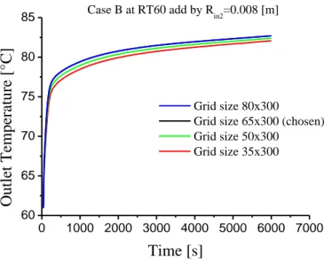
Fig 4.5 Grid size independency of the second configuration case B at Rt60 add by Rin2=0.008[m] ... 51
Fig 4.6 Validation of HTF outlet temperatures in charging and discharging cycle ... 51
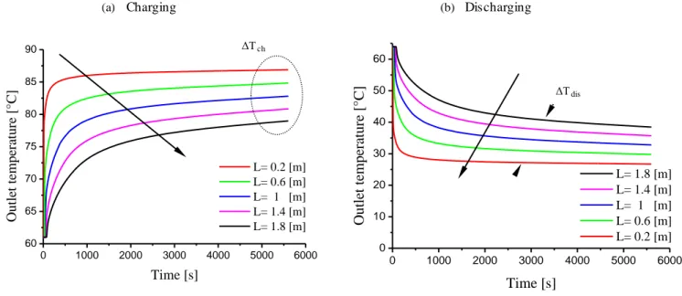
Fig 4.7 Effect of tube length in charging and discharging cycle ... 53
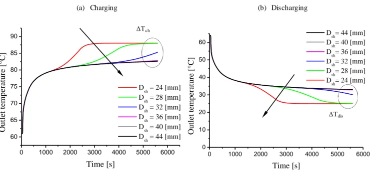
Fig 4.8 Effect of shell diameter in charging and discharging cycle ... 54
Fig 4.9 Effect of Reynolds number in charging and discharging cycle ... 55
Fig 4.10 Charging and discharging cycle of the second configuration II.A ... 57
Fig 4.11 Charging and discharging cycle of the second configuration II.B... 58
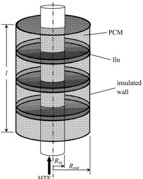
Fig 4.12 A vertical shell and tube thermal energy storage unit configuration. ... 59
X
Fig 4.14 Independency test for different grid size cells during melting process at point a ... 61
Fig 4.15 Validation of the numerical model at points a, b, c during melting process. ... 62
Fig 4.16 PCM temperature variations in pure conduction model and combined model (conduction and convection) at alpha=0°during melting process. ... 64
Fig 4.17 Liquid fraction contour of Pure conduction (a) and combined heat transfer mode (b) at alpha=0°... 65
Fig 4.18 Liquid fraction of combined heat transfer mode at various inclination angles ... 67
Fig 4.19 Axial temperature distributions in different plants of the PCM left region... 69
Fig 4.20 Axial temperature distributions in different plans of the PCM right region ... 71
XI
Lists of Tables
Chapter 1
Table 1.1 Typical materials used in sensible heat storage systems ... 6
Table 1.2 Measured thermo physical data of some PCMs... 15
Table 1.3 Advantages and disadvantages of PCMs ... 15
Table 1.4 Some chemical reactions for thermal energy storage ... 18
Chapter 4 Table 4.1 Thermo-physical properties of PCMs and HTF [(Regin, Solanki and Saini 2006), (Campos-Celador et al. 2014), (Da Veiga 2002)]... 49
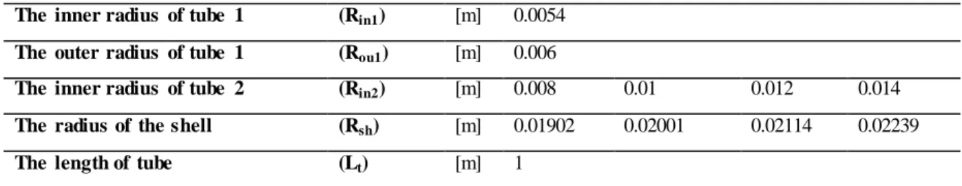
Table 4.2 Geometric parameters of the configuration I (configuration of (Kibria et al. 2014)) ... 52
Table 4.3 Geometric parameters of the second configuration II.A ... 57
Table 4.4 Geometric parameters of the second configuration II.B ... 57
General Introduction
Solar energy is among the most promising alternative sources of energy compared to traditional fossil fuels. It is available, there are no ongoing fuel costs and its environmental impact is low. Today, many solar energy systems able to convert solar radiation directly into thermal energy have been developed for low, medium and high temperature heating applications. Solar thermal power generation and solar space heating are examples of industrial applications; domestic applications include solar water heating and solar absorption refrigeration.
The exploitation of thermal solar energy has become desired currently from the companies and even members of society as a result of its diversity utilization and application in the hybrid systems such as water heating; sea water desalination and electricity production in the same cycle which makes it the most renewable energy important especially at the researchers. This demand has driven a various experts to find a solution to aim ensure the energy cycle of this source, where their first hypothesis was to create a thermal storage system in order to provide the night cycle by the energy required. The thermal energy storage (TES) appears to be the most appropriate method for correcting themismatch that sometimes occurs between the supply and demand of energy. It is therefore a very attractive technology for meeting society’s needs and desires for more efficient and environmentally benign energy use.
There are mainly two types of TES systems, that is, sensible (e.g., water and rock) and latent (e.g., water/ice and salt hydrates). For each storage medium, there is a wide variety of choices depending on the temperature range and application. TES via latent heat has received a great deal of interest. Perhaps, the most obvious example of latent TES is the conversion of water to ice.
Heating systems incorporating hot storage material have a distinct size advantage over equivalent capacity chilled water units because of the ability to store large amount of energy as latent heat. TES deals with the storing of energy, usually by cooling, heating, melting, solidifying, or vaporizing a substance, and the energy becomes available as heat when the process is reversed. The selection of a TES is mainly dependent on the storage period required, that is, diurnal or seasonal, economic viability, operating conditions, and so on. In practice, many research and development activities related to energy
have concentrated on efficient energy use and energy savings, leading to energy conservation. In this regard, TES appears to be an attractive thermal application.
Phase-change materials including organic paraffins, metallic alloys and inorganic salts undergo reversible phase transformation. Due to their isothermal behavior during the melting and solidification processes, such materials can be used in such diversified applications as latent heat storage in building or thermal control in electronic modules. A latent heat storage system is preferable to sensible heat storage in applications with a small temperature swing because of its nearly isothermal storing mechanism and high storage density, based on the enthalpy of phase change (latent heat).
In a latent heat thermal storage (LHTS) system, during phase change the solid–liquid interface moves away from the heat transfer surface. In the case of solidification, conduction is the sole transport mechanism, and in the case of melting, natural convection occurs in the melt layer and this generally increases the heat transfer rate compared to the solidification process. During the phase-change process, the surface heat flux decreases due to the increasing thermal resistance of the growing layer of the molten or solidified medium. This thermal resistance is significant in most applications and especially when the organic phase-change materials are used, because the latter have rather low thermal conductivity. The decrease of the heat transfer rate calls for the usage of proper heat transfer enhancement techniques in the LHTS systems.
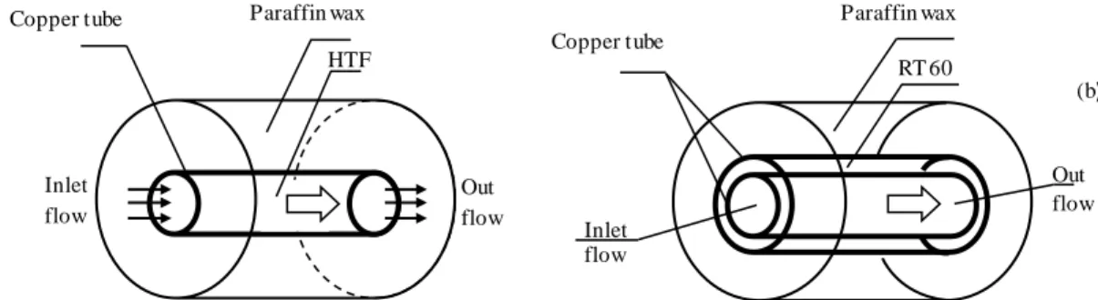
According to the various thermal storage unit configurations, we have used a shell and tube TES unit model which contains two coaxial cylinders. With this unit shape we have made two numerical studies in order to evaluate the thermal behavior of the storage system during phase change process at pure conduction mode. Initially we have made a comparison between unit has a paraffin wax as phase change material and another one has paraffin wax and RT60 which has a close melting points where the numerical outcomes were in terms of the heat temperature flow (HTF). Moreover, we have assess the effect of the unit inclination from the vertical to the horizontal position on the melting process of RT35 PCM that used in another literature. Our thesis is structured as fellow:
Chapter 1 has witnessed general information about energy storage systems such as Mechanical, chemical, electrical storage systems. All this storage fields have a specific method to ensure the continuity of the energy consumption required, where each domain is different to the other in terms of cost and function duration.
Chapter 2 presents an overview of the thermal storage systems such as sensible, latent and thermochemical storage procedure with a concept of latent heat storage thermal energy storage system (TES), and also has clarified different commercial PCMs and PCM systems used.
Chapter 3 introduces the concept of numerical modeling when employed in thermal energy evaluations. It also describes two conventional phase change TES models, and presents a new and validated enhanced phase change model suited specifically for thermal conduction dominant phase changes. In addition to that another study has been conducted to aim assess the effect of the unit inclination on the thermal behavior of the system. Both of studies have the same numerical solving by Ansys Fluent 17 software.
Chapter 4 includes the results obtained for the incorporation of two PCMs in the unit and compared by a single PCM, and then we have made another physical analysis about the inclination effect on the PCM melting progress in terms of melting front rate and temperatures distributions.
The mains reason that was to conduct this modest work is to ameliorate the thermal behavior of the PCMs that have a low or average melting temperature, this kind of materials feature by a weakened thermal conductivity that hinders the heat transfer swiftness inside molten PCM. As results of that, we have chosen the first way that included the adding of the other PCM inside TES unit in order to minimize the charging time of the thermal battery. The second way has comprised the effect of the unit inclination on the phase change physical phenomena of the molten PCM during charging process through a down warding HTF passage that circulate by laminar regime.
Chapter 1
Thermal Energy Storage (TES) Methods
1.1 Introduction
The use of renewable energy sources and increased energy efficiency are the main strategies to reduce the dependency of fossil fuels and CO2 emissions. However, as it is known, renewable energy
sources such as solar and wind energy in particular, are not only characterized by discontinuous availability but are also affected by random variations due to local weather conditions. In this scenario, the availability of energy storage would be essential allowing a large number of solutions and combination of different technologies from already existing power generation systems. Energy storage not only reduces the mismatch between supply and demand but also improves the performance and reliability of energy systems and plays an important role in conserving the energy (Arena 2016).
As to heat storing, a brand new class of materials has been introduced and developed throughout the last decades: activity materials (PCMs). The TES is not a replacement thought, and at has been used for hundreds of years. Energy storage will scale back the time or rate couple between energy offer and energy demand, and it plays a crucial role in energy conservation. Energy storage improves performance of energy systems by smoothing offer and increasing responsibleness.
1.2 Thermal Energy Storage
The thermal energy storage (TES) is a technology that stocks thermal energy by heating or cooling a storage medium so that the stored energy can be used at alters time for heating and cooling applications and power generation. TES systems are used particularly in buildings and industrial processes. In these applications, approximately half of the energy consumed is in the form of thermal energy, the demand for which may vary during any given day and from one day to next. Therefore, TES systems can help balance energy demand and supply on a daily, weekly and even seasonal basis. They can also reduce peak demand, energy consumption, CO2 emissions and costs, while increasing overall efficiency of energy
systems. TES is becoming particularly important for electricity storage in combination with concentrating solar power (CSP) plants where solar heat can be stored for electricity production when sunlight is not available.
There are three kinds of TES systems, namely:
1) Sensible heat storage that is based on storing thermal energy by heating or cooling a liquid or solid storage medium (e.g. water, sand, molten salts, rocks), with water being the cheapest option;
2) Latent heat storage using phase change materials or PCMs (e.g. from a solid state into a liquid state),
3) Thermo-chemical storage (TCS) using chemical reactions to store and release thermal energy. Sensible heat storage is relatively inexpensive compared to PCM and TCS systems and is applicable to domestic systems, district heating and industrial needs.
1.2.1 Sensible TES
Sensible heat water storages are the foremost common TES used these days for domestic functions. In sensible heat storage systems (SHS), energy is keep or extracted by heating or cooling a liquid or a solid that will not modification part throughout the method. SHS consists of a storage medium, an instrumentation (usually a tank) and body of water and outlet devices. The quantity of energy input needed to heat a TES with a smart heat device is proportional to the distinction between the ultimate and initial temperatures of storage, the mass of the storage medium and its heat capability. As Fig 1.1 shows, heat transferred to storage medium results in a linear temperature increase of that medium. From the figure, it can be ascertained that if the temperature of storage medium will increase, its energy content (internal energy) additionally will increase.
Fig 1.1 Linear relationship between energy stored and increased temperature
In sensible heat storage, thermal energy is stored by raising the temperature of a solid or liquid. SHS system utilizes the heat capacity and the change in temperature of the material during the process of charging and discharging. The amount of heat stored depends on the specific heat of the medium, the temperature change and the amount of storage material (Kumar and Shukla 2015).
Q= m (Tf -Ti)
Water appears to be the best SHS liquid available because it is inexpensive and has a high specific heat. However above 100oC, oils, molten salts and liquid metals, etc. are used. For air heating applications rock bed type storage materials are used (Lane 1983).
A large number of materials are available in any required temperature range therefore, the storage material is usually selected according to its heat capacity and the available space for storage. Gases have very low volumetric heat capacity and therefore are not used for sensible heat or cold storage. Table 1.1 reports some common materials used in SHS (Mehling and Cabeza 2008)
Table 1.1 Typical materials used in sensible heat storage systems
Material Density [kg/m3] Specific heat [J/kg∙K] Volumetric thermal capacity [MJ/m3 ∙K] Clay 1458 879 1.28 Brick 1800 837 1.51 Sandstone 2200 712 1.57 Wood 700 2390 1.67 Concrete 2000 880 1.76 Glass 2710 837 2.27 Aluminium 2710 896 2.43 Iron 7900 452 3.57 Steel 7840 465 3.68 Gravelly earth 2050 1840 3.77 Magnetite 5177 752 3.89 Water 988 4182 4.17
Water appears to be the best available liquid SHS because it is cheap and has a high specific heat and volumetric thermal capacity. However above 100 °C, materials such as oils, molten salts and liquid metals are preferred since water should be pressurized. For air heating applications rock or metal bed type storage materials are used (Sharma et al. 2009).
1.2.2 Latent TES
Latent heat storage system LHS use the energy absorbed or released during the isothermal change of materials. Latent heat is defined as the amount of heat stored in the material resulting in change of the material’s phase with a slight increase or decrease in temperature. It takes place when the phase is changing either from solid to liquid, solid-solid and/or liquid to vapor and vice versa, representing the charging energy required and the discharging energy potential when used in any application. However it is important to mention, that there are many studies pointing out the potential of PCMs, but only few PCM are commercialized and suitable for technical processes (Kandalkar, Deshmukh and Kolhekar). The storage capacity of the LHS system with a solid-liquid process is given by:
Q= m [∫ ∫ ] The first term of the second member is the sensible heat of the solid phase, represents the specific latent heat and, finally, the third term is the sensible heat of the liquid phase. In the Equation (1.3), ,s and , are specific heat of solid and liquid phase respectively and is the melting temperature of the material.
A different mechanism for the storage of energy involves phase transitions with no change in the chemical composition. This is characteristic of phase transitions in elements and compounds that melt congruently, that is, the solid and liquid phases have the same chemical composition. There are also phase transitions in which both phases are solids. As an example, there is a transition between the alpha and beta phases in titanium at 882C. The alpha, lower temperature, phase has a hexagonal crystal structure, whereas the beta phase has a body-centered cubic crystal structure. Because they have different crystal structures they have different values of configurationally entropy, and there is a corresponding change in the enthalpy. In these cases, latent heat is absorbed or supplied at a constant temperature, rather than over a range of temperature, as it is with sensible heat. Isothermal latent heat systems are generally physically much smaller than sensible heat systems of comparable capacity. A further simple example is water. At low temperatures it is solid, at intermediate temperatures it becomes a liquid, and at high temperatures it converts to a gas. Thus, it can undergo two phase transitions, with associated changes in entropy and enthalpy. The Gibbs free energy, or chemical potential, is continuous, for the two phases are in equilibrium with each other at the transition temperature. (Huggins 2010)
1.2.2.1 Phase Change Materials (PCMs)
Phase Change Materials (PCMs) are ideal products for thermal management solutions. This is because they store and release thermal energy during the process of melting & freezing (changing from one phase to another). When such a material freezes, it releases large amounts of energy in the form of latent heat of fusion, or energy of crystallization. Conversely, when the material is melted, an equal amount of energy is absorbed from the immediate environment as it changes from solid to liquid as schematically shown in the Fig 1.2.
Fig 1.2 Schematic representation of phase change process (Socaciu 2012)
This property of PCMs can be used in a number of ways, such as thermal energy storage whereby heat or coolness can be stored from one process or period in time, and used at a later date or different location. PCMs are also very useful in providing thermal barriers or insulation, for example in temperature controlled transport. The simplest, cheapest, and most effective phase change material is water/ice. Unfortunately, the freezing temperature of water is fixed at 0°C (32°F), which makes it unsuitable for the majority of energy storage applications. Therefore a number of different materials have been identified and developed to offer products that freeze and melt like water/ice, but at temperatures from the cryogenic range to several hundred degrees centigrade.
1.2.2.2 Types of PCM
Fig 1.3 illustrates a classification of PCMs, but generally speaking PCMs can be broadly classified into two types: Organic PCMs e.g. Paraffin Wax and Inorganic PCMs e.g. Salt Hydrates (Ravikumar and Srinivasan 2008), (Socaciu 2012), (Zalba et al. 2003)
Early efforts in the development of latent TES materials used inorganic PCMs. These materials are salt hydrates, including Glauber’s salt (sodium sulphate decahydrate), which was studied extensively in the early stages of research into PCMs (Patil et al. 2012),(Farid et al. 2004).
The materials which are to used for thermal energy storage unit must have a high value of latent heat and thermal conductivity. They should have melting temperature lying in the practical range of operation, melt congruently with minimum subcooling and be chemically stable. It should be low in cost, nontoxic and noncorrosive. Materials that have been studied during the last 40 years are hydrated salts, paraffin waxes, fatty acids and eutectics of organic and non-organic compounds. Phase change materials should first be selected on the basis of their melting temperature and their applications. For air conditioning purposes, materials of melting temperature below 15oC is to be selected, while materials that melts above 90oC are used for absorption refrigeration system. All other materials that melt between these two temperatures can be applied in solar heating and for heat load leveling applications. These materials represent the class of materials that has been studied most (Kumar and Shukla 2015)
1.2.2.2.1 Organic phase change materials
Organic PCMs are further described as paraffins and non paraffins. The main interest with organic materials is that they involve long term cyclic chemical and thermal stability without phase segregation and consequent crystallize with little or even no supercooling. Finally, they are non corrosive which is an important feature as listed previously. Sub groups of organic materials include paraffin and non-paraffin organics. Paraffin consists of a mixture of n-alkanes CH3-(CH2 )-CH3 into which the
crystallization of the (CH3 ) - chain is responsible for a large amount of energy absorption. The
latent heat of fusion of paraffin varies from nearly 170 kJ/kg to 270 kJ/kg between 5oC to 80oC which makes them suitable for building and solar applications. Non-paraffin organic materials are the most common of the PCMs and they involved varying properties. Although fatty acids are somewhat better than other non paraffin organics, they are even more expensive than paraffins (Abhat 1983). The development of a latent heat thermal energy storage system involves the understanding of three essential subjects: phase change materials, containers materials and heat exchangers (Kumar and Shukla 2015).
1.2.2.2.2 Inorganic phase change materials
Inorganic PCMs are (mostly) used in high-temperature solar applications and one of the most reported challenges is their maintenance. At lower temperatures, they freeze; at high temperatures, they are difficult to handle (Sarbu and Sebarchievici 2018). These PCMs do not super-cool appreciably and their melting enthalpies do not degrade with cycling. The two main types are as follows:
(1) Salt hydrate. This is classified as a congruent, incongruent, and semi-congruent melting method (Sharma et al. 2009) They are alloys of inorganic salts (AB) and n (kmol) of water, forming a typical crystalline solid of general formula AB·nH2O, whose solid–liquid transition is actually a dehydration and
hydration of the salt. A salt hydrate usually melts either to a salt hydrate with fewer moles of water, i.e., AB · n H2O → AB · m H2O + (n − m) H2O
Or to its anhydrous form,
AB · n H2O → AB + n H2O
At the melting point, the hydrate crystals break-up into anhydrous salt and water, or into a lower hydrate and water. One problem with most salt hydrates is that of incongruent melting caused by the fact that the released water of crystallization is not sufficient to dissolve all the solid phase present. Due to density difference, the lower hydrate (or anhydrous salt) settles down at the bottom of the container.
(2) Metallic. This category includes the low melting point metals and their alloys. They are scarcely used in heat storage applications because of their low melting enthalpy per unit weight, even if they have high melting enthalpy per unit volume and high thermal conductivity (Ge et al. 2013). Some of the features of these materials are as follows: (i) low heat of fusion per unit weight; (ii) high heat of fusion per unit volume; (iii) high thermal conductivity; (iv) low specific heat; (v) relatively low vapor pressure.
An inorganic mixture based on an industrial by product (bischofite) was developed and characterized for its application as a PCM for low-temperature thermal energy storage (Galazutdinova et al. 2017) The most appropriate composition was established as 40 wt % bischofite and 60 wt % Mg(NO3)2·6H2O.
Thermo physical properties, specific heat capacity, cycling, and thermal stability were determined. In addition, it was shown that supercooling may be reduced by increasing the quantity of material. (Sarbu and Sebarchievici 2018)
1.2.2.2.3 Eutectics
A eutectic phase change material is a minimum-melting composition of two or more components, where each component melts and freezes in an orderly and balanced manner. (Sharma et al. 2009) Unlike salt hydrates, eutectic PCMs nearly always melt and freeze without separation.
1.2.2.3 Difficulties with PCMs
Latent heat storage is realized by storing or releasing thermal energy through the phase change process of thermal mediums which is called phase change materials (PCMs). Compared with sensible heat storage materials, PCMs have advantages of high energy storage density and thermal energy storage at a nearly constant temperature. The forms of phase change are solid-solid, solid-liquid, solid-gas and liquid-gas. Solid-gas and liquid-gas have high latent heat compared with others. However, they have great difficulty in practical thermal energy storage application, such as large volume change during solid-gas or liquid- gas phase transition.
The solid-solid phase change has the advantage of small volume change during phase transition, but its latent heat is usually much smaller than the others. Solid-liquid transformation has comparatively larger latent heat than solid and smaller volume change than gas and liquid-gas. Therefore, solid-liquid PCMs are commonly used in the applications of thermal energy storage. The main selection
principles of PCMs are as follows high latent heat, desirable phase change temperature, high thermal conductivity, small volume changes, little or no supercooling, good chemical stability, no chemical decomposition and corrosion resistance to container.
Because of the increasing people’s living standard and decreasing energy supply, thermal energy storage can be applied in the fields of solar energy utilization, intelligent building, thermal regulating fabric, waste heat recovery, battery thermal management system, cool storage air-conditioning technology, etc. Consequently, the development of different thermal energy storage technologies will be urgently required. In the context of different applications, thermal energy storage plays different roles. And it can be used as thermal energy storage bodies or auxiliary thermal buffer for heat dissipation. Currently, PCMs are the most widely used thermal energy storage materials, and their state can be stationary or flowing when applied.
In solar energy utilization and industrial waste heat recovery, PCM store solar energy in the form of latent heat and release the stored thermal energy when necessary. This solves the problem of low density, instability and discontinuity of solar radiation with time of the day and the day of the year when utilizing solar energy, or makes a balance between the supply and demand of waste heat in time and space. Different PCMs have different types in solar energy utilization and industrial waste heat recovery. Organic PCMs are mainly used for low temperature utilization of solar energy and industrial waste heat recovery, while inorganic salt, metals and alloys are mainly used for high temperature utilization of solar energy and industrial waste heat recovery.
Application of thermal energy storage technology in solar energy utilization and 89 industrial waste heat recoveries effectively alleviates environment pollution and increases the energy utilization. However, in the field of either solar energy utilization or industrial waste heat recovery, thermal energy storage technology has not yet been put into widespread use. It has many technical problems in practical application, such as high cost, short life of energy storage system, low thermal conductivity of PCMs and energy storage material’s high corrosion to equipment. Therefore, the application of thermal energy storage technology in the fields of solar thermal utilization and industrial waste heat recovery can be optimized by improving the thermal conductivity of PCMs, optimizing the energy storage system and reducing the cost in future works.
PCMs have been gradually applied in intelligent building since 1970s. The thermal energy storage technology used for intelligent building is impregnating the PCMs into construction materials, including concrete, plaster, gypsum board or wall surface coating. The PCMs can store surplus cold or heat which is produced by air conditioning, heater and ambient natural environment.
When the indoor temperature of the building is too high or too low, the PCM relieves the stored cold or heat to indoor ambient. Thereby, the indoor comfort is improved by reducing the fluctuation of
indoor temperature. In addition, the PCM can be used to store cold energy converted from electric energy by refrigerating machine in the night and then release cold energy during middle-of-the-day peak period. The application of PCMs in building has good economy for users especially in the areas where peak-valley electricity price exists. But there are three factors that restrict the wide application of PCMs in the field of intelligent building. Firstly, the reversibility and stability of PCM/construction material composites need to be improved.
Secondly, the PCM is liable to leak from construction material after long term thermal cycling. Thirdly, the thermal stress produced during the phase transformation and corrosion of PCMs leads to the destruction of the construction material. Hence the compatibility, stability and durability of PCMs and construction materials need to be further improved by packaging technology of microcapsule and improvement of compound technology of PCM and construction material (Liu and Rao 2017).
1.2.2.4 Applications of PCMs
The intermittent and dynamic nature of solar irradiance contrasts with the necessity to use solar energy in a continuous and static way, which makes the use of energy storage systems essential for solar energy applications. The most common method of thermal energy storage is the sensible heat method, which utilizes the heat capacity and the change in temperature of a given material during the process of charging and discharging. In contrast, solid–liquid PCMs absorb a lot of heat energy during phase changes without any change in temperature. This latent heat of fusion, which is large, compared to the heat capacity, is promising for thermal energy storage and heat transfer because, unlike the sensible heat storage method, the PCM storage method provides much higher storage density, with a smaller temperature difference when storing and releasing heat.
Many different PCMs have been studied in this application, including paraffin waxes, salt hydrates, fatty acids, and eutectic compounds. Depending on the applications, PCMs reselected on the basis of their melting points. For example, PCMs below 158C have been used for air conditioning applications, while PCMs that melt above 908C are available for absorption refrigeration. All other materials that melt between these two temperatures can be applied in solar energy storage applications.
Extensive efforts have been made to apply the latent heat storage method to solar energy systems. For example, a new method for satellite power testing using PCMs has been put forward by Revenger, in which a series of metal PCM cells that are liquid under high temperatures are utilized. The heat released during the relatively cold dark periods can be used to generate electricity through a thermoelectric device. This system can generate at least three times more power than batteries of comparable size, and can therefore be seen as a possible alternative to the conventional satellite solar power system that relies on batteries. Similar to addressing the solar cycle issues, several projects have been devoted to the
development of PCM systems to utilize off-peak electricity, as PCMs can melt or freeze to store electrical energy in the form of latent heat, and the energy is then available when needed. These systems, coupled with conventional active systems, can reduce the peak load. The shift of the peak load to the off-peak load will provide economic benefits, because the electricity tariff is much cheaper at night than during the day in many countries. An active floor system is effective for the off-peak storage of thermal energy. For example, a layer of paraffin wax (map. 40 8C) placed between the heating surface and the floor tiles significantly increased the heat output of the floor from 30Wm_2 to 75 Wm_2. (Hyun et al. 2014)
1.2.2.5 Characterization of PCMs
As the knowledge of the behavior of heat storage materials is very essential to design an application it is important to characterize these materials. The important characteristics of heat storage materials are their heat capacity, the thermal conductivity, the density and viscosity all in dependency on temperature. All these parameters are necessary to size a thermal storage or to develop heat exchanger to charge and discharge such storages. Simulations are also very often used to analyze applications or components of it and their interaction with the storage material. Such simulations will not be valid if the used material data is not describing its behavior in a correct way, so also for this purpose good and reliable results from the characterization are needed.
Talking about PCMs means to have a very strong relationship between temperature and the mentioned characteristics. In principle, it seems to be very easy to characterize materials since there is equipment available to determine all the needed parameter, but unfortunately, the way in which the materials will be measured influences the results.
The working activities of some groups aim to develop measurement procedures for thermal storage materials. The goal is to introduce standard procedures to make it possible to compare measurement results obtained using different measurement equipment at different laboratories.
To determine the differences in characterization of heat storage materials for heat capacity and melting behavior, viscosity, thermal conductivity, density and cycle stability, water uptake (TCM).
To develop measurement standards to obtain the “real” materials characteristic.
To develop a standards that lead to the “same” results also when they are determined at different laboratories (Gschwander et al. 2011).
When electronics are operated under transient conditions, increasing the thermal capacitance is a useful technique for limiting temperature increases and/or minimizing the performance requirements of a heat sink. One effective method of increasing thermal capacitance is to include a material that undergoes a change of phase at a desirable temperature. Examples of phase change that have been used in electronics cooling include solid-liquid, liquid-vapor, and solid-solid (e.g., crystalline structure to
amorphous). A solid-liquid phase change is most common for systems that require reuse of the phase change material (PCM). The thermal energy required to melt the PCM is frequently described as the latent heat of fusion. Directing the waste heat from electronics into the PCM can result in a nearly isothermal heat sink while the PCM is melting.
Selecting a PCM for use in electronics cooling requires knowing the range of expected temperatures (the melt temperature of the PCM must be high enough such that melting does not occur until needed). Unfortunately, just knowing the desired melt temperature is not sufficient to select a PCM. There are hundreds of materials that melt in a temperature range useful for electronics cooling.
However, the list of candidates becomes much smaller when issues such as material compatibility, toxicity, availability of thermal property data, and cost are considered.
Desirable characteristics of a solid-liquid PCM include high heat of fusion per volume, congruent melting and freezing characteristics, high thermal conductivity, minimal supercooling, and low thermal expansion. As is the case with most materials, searching for thermal property data will reveal some variability (and in many cases, complete thermal data doesn’t exist for some compounds). The organic paraffins represent a reasonable compromise between handling and performance and are available in a wide range of melt temperatures. In general, higher melt temperature paraffins are more expensive, especially for high purity levels. Low thermal conductivity of these materials usually requires the use of an imbedded matrix material to help conduct heat into the PCM. The volume change between solid and liquid states limits their packaging density. (Yu et al. 2012). Table 1.2 presents experimental data on melting temperature, heat of fusion, thermal conductivity and density data for several organic and inorganic compounds, aromatics, and fatty acids, where Table 1.3 shows some advantages and disadvantages of PCMs. Latent TES using PCMs provides an effective way to store thermal energy from a range of sources, high storage capacity, and heat recovery at almost constant temperatures.
Table 1.2 Measured thermo physical data of some PCMs
Compound Melting temper atur e
Heat of fusion
Thermal conducti vity Density
(◦C) (kJ/kg) (W/mK) (kg/m3) Inorganics MgCl2·6H2O Mg(NO3)2·6H2O 117 89 168.6 162.8 0.570 (liquid, 120 ◦C) 0.694 (solid, 90 ◦C) 0.490 (liquid, 95 ◦C) 1450 (liquid, 120 ◦C) 1569 (solid, 20 ◦C) 1550 (liquid, 94 ◦C) Ba(OH)2·8H2O 78 265.7 0.611 (solid, 37 ◦C) 0.653 (liquid, 85.7 ◦C) 1636 (solid, 25 ◦C) 1937 (liquid, 84 ◦C) Zn(NO3)2·6H2O 36 1.255 (solid, 23 ◦C) 2070 (solid, 24 ◦C) 1828 (liquid, 36 ◦C) CaBr2·6H2O 34 146.9 0.464 (liquid, 39.9 ◦C) – 1937 (liquid, 84 ◦C) 1956 (liquid, 35 ◦C) CaCl2·6H2O 29 115.5 190.8 – – 0.540 (liquid, 38.7 ◦C) 2194 (solid, 24 ◦C) 1562 (liquid, 32 ◦C) 1802 (solid, 24 ◦C) Organics Paraffin wax Polyglycol E400 64 8 173.6 99.6 0.167 (liquid, 63.5 ◦C) 0.346 (solid, 33.6 ◦C) 0.187 (liquid, 38.6 ◦C) 790 (liquid, 65 ◦C) 916 (solid, 24 ◦C) 1125 (liquid, 25 ◦C) Polyglycol E600 22 127.2 – 0.187 (liquid, 38.6 ◦C) 1228 (solid, 3 ◦C) 1126 (liquid, 25 ◦C) Polyglycol E6000 66 190.0 – – 1232 (solid, 4 ◦C) 1085 (liquid, 70 ◦C)
Stearic acid 69 202.5 – 848 (liquid, 70 ◦C)
Palmitic acid 64 185.4 0.162 (liquid, 68.4 ◦C) 965 (solid, 24 ◦C)
850 (liquid, 65 ◦C) Capric acid 32 152.7 – 0.153 (liquid, 38.5 ◦C) 989 (solid, 24 ◦C) 878 (liquid, 45 ◦C) Caprylic acid 16 148.5 – 0.149 (liquid, 38.6 ◦C) 1004 (solid, 24 ◦C) 901 (liquid, 30 ◦C) Biphenyl Naphthalene 71 80 119.2 147.7 – – 0.132 (liquid, 83.8 ◦C) 991 (liquid, 73 ◦C) 991 (liquid, 73 ◦C) 976 (liquid, 84 ◦C)
Table 1.3 Advantages and disadvantages of PCMs
Organic (Paraffins) Inorganic (Salt Hydrates) Advantages -non-corrosive;
-chemically and thermally stable; -no or little sub-cooling.
-high melting enthalpy; -high density.
Disadvantages -lower melting enthalpy; -lower density;
-low thermal conductivity; -flammable.
-sub-cooling; -corrosive; -phase separation;
-phase segregation, lack of thermal stability; -cycling stability.
1.2.2.6 Selection of PCMs for Latent TES
Many thermodynamic criteria must be met in order for a PCM to be considered a viable PCM. The material should have a large enthalpy of transition, i.e. latent heat. The purpose of a PCM is to store heat, so the more heat stored the better the material. However, it is important to consider if the specific or volumetric latent heat is more important for the application. Typically, space is the limiting factor, so more often the volumetric latent heat should be considered. Since density changes on phase change and as a function of temperature, the lowest density in the operating temperature range is used to calculate volumetric latent heat; at the lowest density the material takes up the most volume, which sets the size of the PCM. The material should have a high heat capacity in both the liquid and solid phase. As few applications use only the latent heat of a material, having a high heat capacity allows for more thermal storage in the sensible regime.
For the application desired, the PCM should have an appropriate melting point, Tm. If the material does
not have a melting point at the application temperature, the PCM is no better than a sensible heat storage material. The material should have a congruent melting point and a small melting range. Impure materials or incongruently melting materials can have wide melting temperature ranges which complicate matters when thermally cycling. For example, stratification may occur with heavier portions settling to the bottom. A high thermal conductivity is also needed. Materials with high thermal conductivity allow quick heating and cooling to occur for good power input and output. PCMs have a few kinetic criteria that must be met as well. They should exhibit a small amount of super-cooling, which occurs when a material fails to crystallize at its melting temperature. Most materials supercool a few degrees but some PCMs can exhibit super-cooling on the order of 80 K. The crystal growth rate of the material must also be high. When the materials begin to solidify, if the rate is too slow, it is difficult to take energy out of the system. Crystal growth rate is a complicated problem that is related to a number of material properties, from viscosity to thermal conductivity. Essentially, the growth rate is dependent on the heat and mass transfer properties of the material. The chemical criteria are mostly related to safety and containment issues.
The PCM must have long term chemical stability, and be able to withstand thousands of repeated freeze-thaw cycles without degrading significantly. To minimize leakage, the material should be non-corrosive, as corrosive materials can eat away at containers. Chemical reactions between the container and PCM should be kept at a minimum. Little or no leakage should occur during the life of the PCM but in the case that there is an accident; the PCM should be non-flammable and non-toxic, neither deadly nor
harmful. Finally, there are a few economic requirements that must be considered. Since most applications require large amounts of PCM, the cost of the PCM must be low. Of course, there is some uncertainty here because of the fluctuation of market prices and the possibility that alternative manufacturing methods might be developed for the material should the demand be increased. At the very least the material should not contain any rare elements since this would unnecessarily increase the cost. The material should also be environmentally friendly. If the goal of using PCMs is to help reduce greenhouse gas emissions and save energy, then the material should not be excessively difficult to produce or cause undue environmental damage in its production. No single material can possibly fulfill all of these stringent requirements, and engineering solutions must be made to accommodate any shortfalls (Mehling and Cabeza 2008)
1.2.3 Thermo-chemical TES unit
The thermo-chemical storage (TCS) uses thermo-chemical materials (TCM), which store and release heat by recersible dothermic/exothermic reaction process (Fig 1.4 c). During the charging process, heat is applied to the material A, resulting in a separation of two parts B + C. The resulting reaction products can be easily separated and stored until the discharge process is required. Then, the two parts B + C are mixed at suitable pressure and temperature conditions, and energy is released. The products B and C can be stored separately, and thermal losses from the storage units are restricted to sensible heat effects, which are usually small compared to those of the heat of reaction. Thermal decomposition of metal oxides for energy storage has been considered (Kerskes et al. 2012). These reactions may have an advantage in that the oxygen evolved can be used for other purposes or discarded and that oxygen from the atmosphere can be used in the reverse reactions. (Sarbu and Sebarchievici 2018)
Fig 1.4 Methods of thermal energy storage: (a) sensible heat; (b) latent heat; (c) thermo -chemical
reactions (de Gracia and Cabeza 2015).
Thermo-chemical reactions, such as adsorption (i.e., adhesion of a substance to the surface of another solid or liquid), can be used to store heat and cold, as well as to control humidity. The high storage
![Fig. 4.4 Grid size independency of the second configuration case A at RT60 add by R in2 =0.008[m]](https://thumb-eu.123doks.com/thumbv2/123doknet/7780106.258354/70.893.96.844.471.637/fig-grid-size-independency-second-configuration-case-rt.webp)
![Fig 4.9 Effect of Reynolds number in charging and discharging cycle 0100020003000400050006000505560657075808590Outlet temperature [°C]Time [s] Re= 1500 Re= 1000 Re= 500 Re= 200 Re= 100ΔTch ΔT dis](https://thumb-eu.123doks.com/thumbv2/123doknet/7780106.258354/75.893.80.816.695.1041/effect-reynolds-number-charging-discharging-outlet-temperature-δtch.webp)