HAL Id: tel-01662486
https://tel.archives-ouvertes.fr/tel-01662486
Submitted on 13 Dec 2017
HAL is a multi-disciplinary open access archive for the deposit and dissemination of sci-entific research documents, whether they are pub-lished or not. The documents may come from teaching and research institutions in France or abroad, or from public or private research centers.
L’archive ouverte pluridisciplinaire HAL, est destinée au dépôt et à la diffusion de documents scientifiques de niveau recherche, publiés ou non, émanant des établissements d’enseignement et de recherche français ou étrangers, des laboratoires publics ou privés.
d’interface cerveau-ordinateur
Pierre Gergondet
To cite this version:
Pierre Gergondet. Commande d’humanoïdes robotiques ou avatars à partir d’interface cerveau-ordinateur. Automatique / Robotique. Université Montpellier II - Sciences et Techniques du Langue-doc, 2014. Français. �NNT : 2014MON20134�. �tel-01662486�
UNIVERSITÉ MONTPELLIER 2
SCIENCES ET TECHNIQUES DU LANGUEDOC
THÈSE
pour obtenir le grade de
D
OCTEUR DE L
’U
NIVERSITÉ
M
ONTPELLIER
2
Discipline : SYAM – Systèmes Automatiques et Microélectroniques École Doctorale : I2S – Information, Structures, Systèmes
présentée par
Pierre GERGONDET
Équipes d’accueil : LABORATOIRE D’INFORMATIQUE, DEROBOTIQUE
ET DEMICROÉLECTRONIQUE DEMONTPELLIER
CNRS-AIST JRL, UMI3218/CRT(TSUKUBA, JAPON)
Titre :
Commande d’humanoïdes robotiques ou avatars
à partir d’interface cerveau-ordinateur
Présentée et soutenue publiquement le 19 décembre 2014
JURY
Etienne BURDET Rapporteurs
Gordon CHENG
Tetiana AKSENOVA Examinateurs
Philippe FRAISSE
Contents
Introduction 7
1 Brain-Computer Interface as a Control Interface: State of the Art 13
1.1 Acquisition technologies . . . 14
1.1.1 Invasive solutions . . . 15
1.1.2 Functional Near Infrared Spectroscopy (fNIRS) . . . 16
1.1.3 Functional Magnetic Resonance Imaging (fMRI) . . . 17
1.1.4 Electro-encephalography (EEG) . . . 17
1.1.5 Summary . . . 18
1.2 Features used in EEG-based acquisition . . . 19
1.2.1 Motor Imagery . . . 19
1.2.2 Event Related Potentials: P300 . . . 20
1.2.3 Steady-States Visually Evoked Potentials (SSVEP) . . . 22
1.2.4 The Error Potential (ErrP) . . . 26
1.3 BCI Applications . . . 27
1.3.1 BCI-based spelling devices . . . 27
1.3.2 Entertainment, Games and Virtual Reality Applications . . . 29
1.3.3 Robotic Applications . . . 33
1.4 Conclusion . . . 46
1.4.1 Limitations of menu-based control . . . 47
1.4.2 Limitations of NF-based control . . . 47
1.4.3 Introducing “object-centric” BMI . . . 48
2 Building Interface for Robot Control with SSVEP 51 2.1 Introducing the bci-interface: A Framework for Dynamic BCI Application . 52 2.2 Dynamic Background and SSVEP Stimuli Interactions . . . 53
2.2.1 Motivation . . . 53
2.2.2 Material and Methods . . . 55
2.2.3 Experimental Results . . . 57
2.2.4 Discussion . . . 58
2.3 SSVEP stimuli design for object-centric BCI . . . 60
2.3.1 Material and methods . . . 61
2.3.2 Pilot study – Results and discussion . . . 67
2.3.3 SSVEP display optimization – Results and discussion . . . 70
2.3.4 SSVEP Display Optimization: Conclusion . . . 82
2.4 Conclusion . . . 83
3 Whole-Body Control with Steady-State Visually Evoked Potentials (SSVEP) 85 3.1 Introducing Object-Centric BMI . . . 86
3.1.1 From Cartesian-Motion to Task-Space Control . . . 86
3.1.2 From menu-based BMI to object-centric BMI . . . 87
3.2 A framework for object-centric BMI . . . 88
3.2.1 Overview . . . 88
3.2.2 BCI Module . . . 88
3.2.3 SSVEP Interface Module . . . 90
3.2.4 Objects and Affordance Extraction Module . . . 91
3.2.5 Task selection module . . . 91
3.3 SSVEP Interface Module for Object-Centric BMI . . . 91
3.3.1 Recursive and Enforced SSVEP Selection . . . 92
3.3.2 State Transition in BMI . . . 92
3.4 Objects and Affordance Extraction Module . . . 93
3.4.1 Objects Recognition - 2D Recognition: Algorithm . . . 94
3.4.2 Objects Recognition - 2D Recognition: Shape Extraction . . . 95
3.4.3 Objects Recognition - 3D Recognition . . . 95
3.4.4 Robot localization in indoor environments . . . 95
3.5 Implementation of the Task Selection Module . . . 96
3.5.1 Definition . . . 97
3.5.2 Using a Bayesian network as a Task Selection Module . . . 97
3.5.3 Improving the network . . . 98
3.6 Object-oriented Robot Control . . . 99
3.6.1 Walking with a Humanoid Robot in BMI . . . 99
3.6.2 Navigation assistance for humanoid control through BMI . . . 100
3.6.3 Object soft-drop with guarded motion . . . 103
3.6.4 Action Cancellation . . . 104
3.7 User Experiments . . . 106
3.7.1 Initial User Experiment . . . 107
3.7.2 Assessing the benefits of Navigation Assistance . . . 109
3.7.3 A Bayesian-network assisted BCI for Humanoid Robot Control . . 112
Contents 5
4 Humanoid Control with a Brain-Computer Interface: Applications 117
4.1 Studying the Impact of Sound in Embodiment Experience . . . 118
4.1.1 Material and Methods . . . 119
4.1.2 Hardware and software integration . . . 121
4.1.3 Results . . . 122
4.1.4 Discussion . . . 126
4.1.5 Conclusion . . . 127
4.2 Impact of Sound in Embodiment Experience with a Strong Visual Component 129 4.2.1 Introduction . . . 129
4.2.2 Participants . . . 130
4.2.3 Methods . . . 130
4.2.4 Data Analysis: Current Results . . . 131
4.2.5 Discussion and Perspectives . . . 134
4.3 Conclusion . . . 136
5 ECoG-based BCI using a humanoid robot 137 5.1 An introduction to ECoG-based BCI . . . 138
5.1.1 ECoG technology . . . 138
5.1.2 ECoG-based BCI: the CSP method . . . 138
5.2 One degree of freedom ECoG-based BCI . . . 139
5.3 Two degrees of freedom ECoG-based BCI . . . 141
5.3.1 Patient implantation . . . 142
5.3.2 Results of Brain Mapping . . . 142
5.3.3 A synchronized motor-imagery paradigm . . . 144
5.3.4 Experiments . . . 146
5.3.5 Results . . . 146
5.4 Challenges of ECoG-based BCI . . . 147
5.4.1 Problems induced by the surgery . . . 147
5.4.2 Experimenting within the therapeutic process . . . 147
5.5 Perspectives and Conclusion . . . 148
Conclusion and Perspectives 151 Bibliography 155 Appendices 167 A A Framework for Dynamic BCI Application: bci-interface 169 A.1 Motivation and Goals . . . 169
A.2 Command Model in bci-interface . . . 170
A.3 Framework Elements . . . 170
A.3.1 BCIInterface . . . 170
A.3.2 EventHandler . . . 171
A.3.4 DisplayObject . . . 172
A.3.5 CommandReceiver . . . 173
A.3.6 CommandInterpreter . . . 173
A.3.7 CommandOverrider . . . 174
A.4 Workflow . . . 175
A.4.1 The paradigm workflow approach . . . 176
A.5 Examples . . . 177
B Example uses of the bci-interface library 179 B.1 Minimal example: an application for steering . . . 179
B.2 Switching example: control steering and gazing . . . 181
C Users’ questionnaires employed 185 C.1 SSVEP display optimization – user experience questionnaire . . . 185
Introduction
In recent works of fiction such as the movies “Avatar” and “Surrogates”, a system allows a user, using only his thoughts, to experience and interact with the world through a physical copy (e.g. a robot) as if it was her/his own experience. Although state-of-the-art technologies do not allow to do this, recent technological advancements lay the initial bricks of such a system as seen in Figure 1. In order to build a “surrogate” system, one would need to combine these technologies in an efficient manner.
However, traditionally, reproducing the task at the will of the operator on a humanoid robot or an avatar is done by capturing his/her movements. In this thesis, we wish to move away from gesture and movement, which control a task, toward the interpretation of the user’s thoughts. That is the translation of intention into action as seen in Figure 2. At first we plan to achieve only simple control tasks that follow closely telepresence schemes between an operator and a humanoid robot. The demonstrators we build and present in this thesis progressively move away from this simple task to allow complex interactions between the user and its environment through the embodied device.
Figure 2: Concept of the VERE project
This work is conducted in the framework of the European integrated project VERE (Vir-tual Embodiment and Robotics re-Embodiment). Our goal in this project is to devise a soft-ware architecture that integrates a set of control and sensory feedback strategies to physically re-embody a human user into a humanoid robot surrogate or a virtual avatar using his/her own thoughts. The demonstrator we aim to achieve can be described as the following: a user is equipped with a brain-computer interface (BCI) that monitors brain waves activities from which we want to extract intentions and translate them into robotic commands. Sen-sory feedback should be delivered to the user so that s/he can embody the controlled device: virtual or real.
(a) The Geminoid robot aims at investing the question of human presence by mimicing the appearance of a human
being.
(b) A user equipped with several physiological sensors allowing to measure brain and body activity.
(c) Telesar V: a complex telexistence system.
Figure 1: Existing technologies towards a “surrogate” system.
Figure 3: VERE demonstrator with HRP-4
Contents 9 and feedback devices that compose the embodiment station built within the VERE project by another partner (University of Pisa). The intentions of the operator are guessed from his/her thinking and are then transformed into robotic tasks. The humanoid robot then executes these tasks and its sensors outputs are interpreted and properly reproduced for the operator in “close-loop” fashion. The research challenges involved within the realization of such a system are numerous and we now explicit them.
1. Complexity in fully controlling the surrogate’s motion
With technologies currently available, we are not able to extract a precise (motor) in-tention from the user’s brain activity. Hence, our approach requires an important level of shared autonomy, that is the capacity for the robot to make decision on its own while respecting the wishes of the user, and also requires the robot to be able to understand its environment. This later statement involves many things: the robot should know– or learn–how its environment is built, where it is located within this environment and which tasks it can perform. This is made necessary by two equally important aspects. First, the robot needs to understand its environment in order to interact with it in a safe and efficient manner. Second, it also has to be able to communicate its knowl-edge to the BCI so that it is used to better understand the user’s intentions and provide meaningful feedback. In the case of a virtual avatar, this is easier to achieve as the environment is simulated.
2. Minimal motion-based control/coupling
The technologies currently available to recover the user’s intentions from his/her brain are far from achieving the kind of understanding that we can observe in fictional works. They are actually very limited with regards to the number of recognizable intentions, the available bit rate and the accuracy of the recognition. Therefore, we have to devise a number of strategies to obtain the user’s intention through the B-BCI (Body-Brain Computer Interface). Furthermore, these intentions should be mapped into surrogate (robotic) actions.
3. Full synergy and beyond telepresence transparency
The notion of embodiment, central within the VERE project, goes beyond the classical approaches of teleoperation and telepresence. In teleoperation and telepresence, a user controls a remote device and receives feedback (e.g. visual feedback or haptic cues) about the task s/he is executing through the device. In telepresence, this allows the user to feel present at the scene where s/he is executing a task through the device. In embodiment, the user should not only feel present at the remote location but s/he should feel as if the device’s body was his/her own. This requires the introduction of new sensory feedback strategies.
These issues are all dependent upon constantly evolving scientific fields that also drive our overall progress. They cover a large number of research fields and go beyond the scope of a single thesis. We however demonstrate significant progress on each of these issues.
In the first chapter of this thesis, we introduce the general concept of brain-computer interface (BCI) or brain-machine interface (BMI) based on the approach of the most promi-nent frameworks in this field. That is the division between an acquisition layer, a signal processing layer and an application layer. The following sections are organized based on these layers. The most common brain signals’ acquisition technologies are presented and the choice of the electroencephalogram (EEG) technology for the majority of the presented work is justified. Then, an overview of the most common paradigm used in EEG-based BCI to obtain the users’ intentions is presented. Finally, several applications of BCI are then introduced with a particular emphasis on previous works for the control of robotic devices. Based on the examination of those previous works, we propose a novel approach to BMI within the context of humanoid robot and complex tasks execution through embodiment.
In the second chapter, we discuss the tools we developed and problems we encountered within the context of BCI-based robot control. First, we tackle the need for dynamic appli-cations by introducing a novel library to build a user interface for BCI that is (a) easy to use, and (b) able to switch between different behaviors. Then, we show that steady-state visually evoked potentials (SSVEP) recognition performance are affected when the stimuli used to elicit the potentials are overlaid upon a dynamic feedback such as the video stream from a robot’s embedded camera. Finally, we introduce several ways to overlay SSVEP stimuli upon objects recognized by the robot’s vision system. These methods are compared based on both objectives, e.g. recognition accuracy, and subjective ones, e.g. user appreciation, criteria.
In the third chapter, we focus on the use of the SSVEP paradigm to perform whole-body control of a humanoid robot and further introduce the concept of object-centric BMI. In the first part, a general introduction of the object-centric BMI needs and principle is given. Then, a framework to realize object-centric BMI is proposed and its components are intro-duced individually. The second part of the chapter focuses on the technical modules that are required to implement this framework on a humanoid robot; including SSVEP-based paradigms allowing reliable and recursive selections, robot control bricks that allow us to perform task-oriented control and finally the vision elements that permits objects recognition and object-oriented navigation. Finally, several user experiments show that the framework allows an efficient control of the humanoid robot using a BCI.
In the fourth chapter, we use the tools introduced in the previous two chapters to perform embodiment studies using the humanoid robot controlled with BCI as a platform. The chap-ter is particularly focused on two studies conducted in collaboration with the Fundazione Santa Lucia (FSL). In the first study, the subjects control the robot while being subject to different modalities of sound feedback. A second experiment is also introduced. In this experiment, the subjects are equipped with a head-mounted display (HMD) which implies that the experiment is more immersive from the get-go. Therefore, the effect of the differ-ent sound modalities is differdiffer-ent from the first experimdiffer-ent. Moreover, patidiffer-ents afflicted with spinal cord injuries (SCI patients) participated in this later experiment.
The fifth and final chapter describes preliminary results obtained from experiments that used electrocorticography (ECoG) to acquire the signals from the user’s brain. The experi-ments were performed on two patients who had undergone surgery within an epilepsy-related
Contents 11 treatment. The results of these initial experiments are presented and we discuss the chal-lenges posed by ECoG-based BCI.
We end our thesis with a summary of our contribution and future works and openings. In the next chapter, we present succinctly work from the state-of-art that serves as background of our achievements.
Chapter
1
Brain-Computer Interface as a
Control Interface: State of the Art
Brain-computer interfaces (BCI) [1] [2], or brain-machine interfaces (BMI), allow bypassing the usual means of communication channels between a human and a computer or a machine such as hand or voice input devices (e.g. keyboard, mouse, joysticks, voice command micro-phones, etc.). Instead, they allow the users to communicate their intentions to the computer by processing the source of the intentions: the brain activity. In return, the user is able to control different application (software or device) systems connected to the BCI. Combining this technology with a humanoid robot, we envision the possibility of incarnating one’s body into a robotic avatar. Such a goal is pursued by the VERE project1in which frame the present
work takes place. In many ways the problem at hands is reminiscent of telepresence technol-ogy. However, the specificities that are brought by the use of a brain-computer interface goes beyond telepresence aims and objectives while at the same time they backtrack substantially the performances. Indeed, in the current state of technology, brain-computer interfaces dif-fer from traditional control interfaces [3], as they have a low information rate, high input lag and erroneous inputs. While the two terms–BCI and BMI–hold the same signification, in this thesis, we prefer the later when referring to the common idea of a BCI while using the second for BCI within the context of robot control.
In recent years, several frameworks such as OpenViBE [4], BCI2000 [5] or TOBI hBCI [6] have introduced a similar three-layer model to produce BCI application as shown in Fig-ure 1.1. The signal acquisition layer monitors the physiological signals from the brain through one or several physical devices and digitizes these signals to pass them to the signal-processing unit. The signal-signal-processing unit is in charge of extracting features —e.g. power spectrum, signal energy— from the raw signals, and pass them onto a classification algo-rithm to distinguish the patterns of intentions of the user. Finally, these decoded intentions
Figure 1.1: General design of a BCI system
are passed to the user application.
In this chapter we present each layer independently. We first present the different ac-quisition technologies that have been used in the BCI context, we discuss their benefits and limitations and we justify the choice of electroencephalography (EEG) in most of our works. The second section focuses on the different paradigms that can be used in EEG-based BCI. Finally, we review previous works that have used BCI as a control input, focusing on previ-ous works in the robotics domain.
1.1 Acquisition technologies
The “reading” of one’s brain activity signals can be done by means of different technologies. However, within the context of brain-computer interface only those that allow measuring the brain activity in real-time or close to real-time are considered. In this section, we present some invasive solutions that have been used and BCI and then we focus on the three most used non-invasive technologies in BCI: functional near infrared spectroscopy (fNIRS), func-tional magnetic resonance imaging (fMRI) and electroencephalography (EEG). The practical pros of these technologies, e.g. the quality of the recorded signals or their spatial localiza-tion accuracy — how precisely one can tell from where in the brain a signal originates, are discussed together with other practical issues such as cost and more importantly the intru-siveness level. Finally, we explain our choice to settle on EEG for most of the applications developed within this work.
1.1 Acquisition technologies 15
Figure 1.2: A typical ECoG array with 20 electrodes, courtesy of Dr Kamada
1.1.1 Invasive solutions
In this section, we introduce a few invasive solutions that have been employed to read the signals of the brain activity. We first introduce the electrocorticography (ECoG) technique, a technology that is considered to be “semi-invasive” and we then present invasive solutions as well as some of their achievements. Obviously those technologies have outstanding qualities from the signal acquisition point of view. However, their very nature also limit their usage. 1.1.1.1 Electrocorticography (ECoG): a “semi-invasive” solution
Electrocorticography (ECoG), also known as intra-cranial EEG (iEEG), is an invasive tech-nology used to measure the brain activity. In this case, the electrodes are placed directly in contact with the surface of the brain, typically using electrodes encompassed in a silastic membrane such as the one shown in Figure 1.2. This solution can be classified as “semi-invasive” because while the ECoG array is put inside the cranium of the patient, the elec-trodes do not penetrate the brain. Therefore it is considered relatively safe compared to the invasive solutions we present later in this section.
Compared to non-invasive technologies the quality of the signal obtained from the ECoG is much higher, offering a spatial resolution of 1cm [7] or even less, with an excellent signal to noise ratio. Furthermore the acquisition rate is also very good: typically reaching 1 kHz.
Recently, ECoG has been featured in impressive works related to robotics [8]. However, the main application of ECoG remains therapeutic as it is considered the “gold standard” for defining epileptogenic zones, a key step in the resolution of severe epilepsy cases. It is most often in this context that ECoG-based BCI experiments are conducted. Therefore, the use of this technology in BCI remains exceptional and implantations last for a few weeks at most. 1.1.1.2 Neuroprosthetics
Neuroprosthetics is the science that deal with the development of neural prostheses. Those prostheses are devices that can substitute a motor or sensory modality that was damaged
Figure 1.3: The BrainGate system, a promising neural prosthesis in development, adapted from [9]
following a disease or an injury. A relatively common example of this kind of device are cochlear implants which aim is to restore the auditory sense for deaf or severely hard of hearing persons. Another notable device is the “Dobelle-eye” which aims at restoring the vision of blind people by stimulating the visual cortex based on the images received by a digital camera worn by the patient.
Motor neuroprosthetics aim to either restore movement capabilities for paralyzed patients or to allow them to use computer and robotic devices to assist them. The first successful ex-ample of such devices in humans goes back to 1998. However, in 2005, Matt Nagle became the first tetraplegic patient able to control an artificial hand through a neural prosthesis: the BrainGate system.
BrainGate consists of a sensor implanted in the brain and an external decoder device, the signal acquisition and signal processing layers of the BCI model. The sensor uses 100 hair-thin electrodes that sense the electromagnetic signature of neurons firing in specific areas of the brain, for example, the area that controls arm movement.
Recently, in a remarkable work using the BrainGate system, a tetraplegic patient was able to control a robotic device to grab a bottle of water and drink from her own volition [10]. We discuss the details of this experiment later in this chapter.
1.1.2 Functional Near Infrared Spectroscopy (fNIRS)
Near-infrared spectroscopy is a general spectroscopic method that uses the near-infrared re-gion of the electromagnetic spectrum. It is used in a wide variety of applications. In particu-lar, it can be applied to perform functional neuroimaging, in which case it is called functional near infrared spectroscopy (fNIRS). It measures the hemodynamic responses associated with neuron behavior thus providing a reading of the brain activity.
fNIR is a non-invasive imaging method involving the quantification of chromophore con-centration resolved from the measurement of near infrared (NIR) light attenuation, temporal
1.1 Acquisition technologies 17 or phasic changes. NIR spectrum light takes advantage of the optical window in which skin, tissue, and bone are mostly transparent to NIR light in the spectrum of 700-900 nm, while hemoglobin (Hb) and deoxygenated-hemoglobin (deoxy-Hb) are stronger absorbers of light. Differences in the absorption spectra of deoxy-Hb and oxy-Hb allow the measurement of relative changes in hemoglobin concentration through the use of light attenuation at multi-ple wavelengths. Two or more wavelengths are selected, with one wavelength above and one below the isobestic point of 810 nm at which deoxy-Hb and oxy-Hb have identical ab-sorption coefficients. Using the modified Beer Lambert law (mBLL), relative concentration can be calculated as a function of total photon path length. Typically the light emitter and detector are placed ipsilaterally on the subjects skull so recorded measurements are due to back-scattered (reflected) light following elliptical pathways. NIRS is functionally very sim-ilar to MRI but it is less costly and more portable. However, it cannot be used to measure cortical activity at more than 4cm deep and its spatial resolution is lower than MRI.
Finally, while fNIRS has been used in BCI, and particularly in robotics [11], it is not as popular as EEG as it is more expensive and slower: as with fMRI, due to the nature of the measured phenomenon, the system is able to detect the user intention a few seconds — 5 to 10 seconds — after this intention is formed in the user’s mind.
1.1.3 Functional Magnetic Resonance Imaging (fMRI)
Magnetic resonance imaging (MRI) is a non-invasive brain signal acquisition technology. The primary form of MRI uses the blood-oxygen-level-dependent (BOLD) contrast. This is a type of specialized brain and body scan used to map neural activity in the brain or spinal cord of humans or other animals by imaging the change in blood flow (hemodynamic response) related to energy use by brain cells.
fMRI is primarily used in brain mapping research as, contrary to methods that can pro-vide similar information, it does not require people to undergo shots, surgery, to ingest substances (radioactive markers), or to be exposed to radiation [12]. However, it has also been used to perform BCI activities. For example, in 2006, the Honda Research Insti-tute Japan (HRI-J) and the Advanced Telecommunications Research InstiInsti-tute International (ATR) presented a robotic hand controlled by fMRI [13]. However, they later switched to an EEG/NIRS hybrid system to control the Asimo robot [14] mainly for practical reasons. Furthermore, as mentioned earlier, the temporal resolution of fMRI makes it difficult to use it effectively in applications requiring the control of multiple behaviors. Current research aims at resolving this issue.
1.1.4 Electro-encephalography (EEG)
Electroencephalography (EEG) is the recording of electrical activity along the scalp. EEG measures voltage fluctuations resulting from ionic current flows within the neurons of the brain. The biggest drawback of this technology is its very poor signal-to-noise ratio, which is mostly due to the fact that the electrical activity of the brain is measured through the skull
Figure 1.4: An EEG user wearing a cap with mounted electrodes and obtained signals
of the subject. Therefore, the spatial resolution of the system is very low and sophisticated signal processing techniques are required to extract useful information.
However, EEG also has significant advantages. First, it has a very high temporal reso-lution. Typically, EEG is recorded between 250 and 2000Hz but the latest technologies are able to achieve a 20000Hz sampling. Secondly, it is relatively tolerant to subject movement. Finally, it is significantly cheaper than other technologies: for example, an fMRI machine typically requires a large magnet and a magnetically shielded room, a very expensive setup.
This is why EEG is by far the most popular acquisition technology used in BCI research.
1.1.5 Summary
The following table shows, for each technology, the different qualities we are looking at when considering our choice for acquisition technology. “Localization” designates the spatial-localization accuracy. “SnR” designates the signal-to-noise ratio. “Cost” designates the cost of the system. Finally “Real-Time” designates the real-time capability of the technology.
Technology Localization SnR Cost Real-Time Invasive
Brain implants +++ +++ – ++ ++
ECoG ++ ++ - ++ Yes
NIRS - - + + No
fMRI ++ ++ – - No
EEG – – ++ ++ No
For BCI applications, EEG has proven to be the most used technology, although it suffers from poor spatial localization accuracy and signal to noise ratio, it has remarkable practi-cal qualities such as low cost, real-time acquisition and most importantly non-invasiveness. Moreover, a wide range of paradigms has been researched using EEG and provide as many ways to understand the BCI user’s intentions.
1.2 Features used in EEG-based acquisition 19 For those practical reasons we decided to adopt EEG in most of our work. However, the framework we will introduce in Chapter 3 is independent of the acqusition technologies or of the intentions’ extraction method employed on the BCI side.
1.2 Features used in EEG-based acquisition
In the field of neuroscience a tremendous work is made to identify brain signal patterns re-lating to one’s intentions or emotions. Nevertheless, the state-of-the-art BCI stands very far from being able to read, as in a book, one’s mind thoughts or intentions by any tech-nology means existing today. The brain is still a mystery in many aspects despite the no-table amount of research conducted in the field. Nevertheless, brain function understanding progress substantially from year to year. Therefore, today’s BCI technology is still confined in a stimuli-response monitoring scheme.
Three major methodologies are used in the BCI field because of their consistency among different untrained users. In this section, we first focus on the motor imagery paradigm where the system detects imagined movements. This paradigm is the only one where intention is guessed from the strength of one’s thought. Then, an event related potential, the P300 is presented. Then, we introduce the steady-state visually evoked potential (SSVEP) that we are using extensively in this thesis. Finally, the error-related potential that could be potentially very useful in control applications, is presented.
1.2.1 Motor Imagery
Motor imagery [15] consists in detecting so-called event related de-synchronization–ERD– and event related synchronization–ERS–which are the decrease or increase of power in the alpha (8–13Hz) and beta (14–30Hz) frequency ranges of the brain activity and which occurs when the user executes or, more interestingly, imagines a movement.
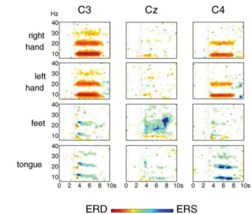
In [16], Pfurtscheller et al. performed a study with 9 subjects to determine the feasibility of 4-classes classification of motor imagery, namely: left-hand, right-hand, feet and tongue movement imagination. In this study, the subjects were seated in an electrically shielded cabin and watched a 15" monitor. A trial lasted 7 seconds. At the beginning, the screen was blank then a cross was displayed in the middle of the screen at second 2. At second 3, an arrow indicated the motor imagery task that should be performed by the subject. They were asked to imagine the kinesthetic experience of movement rather than a visual representation of it and to avoid any motion during the trial. An ERD/ERS is expressed as a percentage in power decrease (ERD) or power increase (ERS) relatively to the 1 second interval prior to the appearance of the cross in a trial at 2 second.
Figure 1.5 show the results of one subject for the 4 motor imagery tasks and 3 of the 60 electrodes as presented in [16]–where a more thorough discussion of the results is provided. These results show that hand motor imagery induces significant ERD in the mu band while foot and tongue motor imagery triggers significant ERS. Pfurtscheller et al. then showed that it was possible to build a classifier for single trial detection with an accuracy
Figure 1.5: Time-frequency maps that shows significant ERD-ERS for one subject, 4 motor imagery tasks and 3 electrodes. Adapted from [16]
between 30% and 50%. However, it has been shown that the subjects could learn to control ERD/ERS thus making such classifiers more accurate. This process is quite long though.
While progress has been made since this early work, this method still requires a long training with the user to achieve useful performance when the system distinguishes multiple classes of movement.
1.2.2 Event Related Potentials: P300
The P300 [17] is an event related potential (ERP). It describes a positive wave in the cerebral activity which occurs 300ms after the occurrence of an expected event among other similar events. It is thought to be related to the process of decision-making.
The P300 is well adapted for systems with a large number of choices - e.g. selecting keys on a keyboard [18] —and has proven to provide very good performance with little training among the population. In [19], a study conducted with 100 persons showed that 90% were able to achieve an accuracy level between 80 and 100% after a 5 minutes training. However, to obtain this kind of performance it is better to have the rare event occur multiple times to properly detect the P300, therefore, while a high bit rate can be achieved with this paradigm, the decision rate is rather low, typically reaching 6 decisions a minute [18].
1.2 Features used in EEG-based acquisition 21 The user is shown a 6 × 6 grid with grayed letters. When the paradigm starts, each row and column is highlighted successively. In this example, the user wishes to select the letter ‘N’. If the letter ‘N’ is not active then nothing particular can be observed from the brain activity. However, when the ‘N’ letter is active, then we can see a positive wave around 300ms after the occurrence of the stimulus, this is the P300. Typically, each row and column is highlighted multiple times to elicit as many potentials as possible and ensure the selection of the user’s choice.
Figure 1.6: The P300 paradigm and associated brain answer: red indicates standard activity, blue shows the P300 triggered, adapted from [20]
While we only presented the paradigm for visual stimuli, it can be noted that the paradigm can also be applied with audio and tactile stimuli [21]. The principle is the same: for audio-based P300, different audio-cues are used instead of the visual stimuli while in tactile-audio-based P300, different tactile stimuli are given to the user. However the performances of audio-based and tactile-audio-based P300 systems are much lower [22] since it is more difficult for the user to distinguish the different stimuli.
Figure 1.7: EEG spectrum when showing a 15Hz stimulus to the user, courtesy of [24].
1.2.3 Steady-States Visually Evoked Potentials (SSVEP)
The Steady-States Visually Evoked Potential (SSVEP) is elicited by presenting the subject with a flickering stimulus. As the user focuses her/his visual attention on the stimulus, a peak can be observed in the power spectrum of the EEG signal recorded from the primary visual cortex at the frequency of the flickering stimulus and other local peaks at this frequency odd harmonics as seen in Figure 1.7. By analyzing the signal we can predict whether the user is attending to a particular stimulus or not. The stimuli can be of various types, including physical LEDs to on-screen flickering objects. State-of-the-art detection systems [23] can operate at a good success rate, i.e. above 80%. The method relies uniquely on the user’s attention to the stimulus, it also allows to detect that the user is maintaining her/his attention on a given stimulus and to detect a shift of attention in a few seconds. This makes SSVEP our preferred feature for reactive control through BCI such as steering control.
Various parameters can affect the strength of the SSVEP answer: the stimulus color, the stimulus shape and size [24] [25] [26] [27]. Moreover, the frequencies have to be carefully selected to have neither common first or second harmonics and to be below 20Hz to minimize the risk of eliciting an epileptic crisis in healthy subjects as advised in [28].
This paradigm can also be a bit tiring because of the annoying nature of the stimulus at low frequencies–typically, because of technical and medical considerations, SSVEP frequen-cies are chosen below 20Hz. It is possible to retrieve SSVEP at very high frequenfrequen-cies [29] but the intensity of the response is much lower and therefore much more difficult to detect.
Given that we are extensively using SSVEP in our work we present the extraction method we use to detect SSVEP from the user’s brain signals. Furthermore, we also introduce the
1.2 Features used in EEG-based acquisition 23 specific method we used to display SSVEP stimuli on a computer screen instead of using a separate flashing box.
1.2.3.1 Minimum Energy Method
To extract the SSVEP from the brain signals, we rely on the minimum energy classification method presented in [30]. It has also been extended to implement a zero-class; that is a classification output that indicates that the user is not attending any stimuli. The signal acquired at a given electrode is modeled as:
yi(t) = Nh
q
k=1ai,ksin(2πkf t + φi,k) + q
j bi,jzj(t) + ei(t)
where yi(t) is the signal acquired at an i-th electrode. The first part of the equation is the
SSVEP response, consisting of sinusoids with frequencies of the stimulus frequency and harmonics of this frequency. The second part of the equation represents the nuisance signals, e.g. non SSVEP activity or movement artifacts. Those are common to all electrodes but have different weight factors bi,j depending on the electrode i. Finally, ei(t) represents the
specific measurement noise of electrode i.
Consecutive Ntsamples are regrouped into the vector form:
yi= Xai+ Zbi+ ei
where yi = [yi(1), · · · , yi(Nt)]⊤ and ei is a similar vector. X is the SSVEP model matrix
of size Nt× 2Nhcontaining sin(2πkft) and cos(2πkft) pair in its columns. ai contains the
corresponding amplitudes. Z and bi are similar constructs for the nuisance signal. Finally,
given that the time segment is short enough, the noise can be assumed constant. Hence, Ny electrodes can be written as a single matrix Y = [y1, · · · , yNy] and the model can be
generalized to:
Y= XA + ZB + E
In order to maximize the SSVEP response while minimizing the noise, a channel is con-structed by a weighted sum of Ny electrodes using a Ny× 1 vector of weights w, that is:
s=
Ny
q
i=1wi
yi = Yw.
furthermore, Nschannels can be combined by constructing different electrodes combination
S= YW where W is a Ny × Nsmatrix containing the different weights combination. The
construction of W is the matter of the minimum energy combination technique.
The idea of this method is to build a combination that cancels the noise signals. To do so, we first remove any potential SSVEP components from the electrode signals, hence:
˜
then we have to find the weight vector ˆwthat minimize the resulting energy of the electrodes
combination. Therefore, we are left with the optimization problem: min ˆ w ë ˜Y ˆwë 2 = min ˆ w wˆ ⊤Y˜⊤Y ˆ˜w
the solution to this optimization problem is the smallest eigenvector v1 of the symmetric
matrix ˜Y⊤Y˜ and the energy of this combination is equal to the smallest eigenvalue λ
1 of
this matrix. Moreover, as ˜Y⊤Y˜ is symmetric, its eigenvectors are orthogonal, thus providing
us with Ny uncorrelated channels with increasing noise energy. The number of channels Ns
retained from the minimum energy method is the smallest number that satisfies:
qNs
i=1λi
qNy
i=1λi
> 0.1
where the denominator is the total energy in the nuisance signals and noise, and the numera-tor is the total energy retained when combinations are used, i.e. Ns discards close to 90% of
the nuisance signal energy. Finally, the channels being selected, the following test statistic is used to test the presence of an SSVEP response:
T = 1 NsNh Ns q l=1 Nh q k=1 ˆ Pk,l ˆ σ2 k,l
where ˆPk,l is an estimate of the power in SSVEP harmonic frequency k in the channel sland
ˆ σ2
k,l is an estimate of the noise in the same frequency and channel. Details regarding those
estimations are provided in [30].
The class that receives the highest score is normally selected. However, this does not account for moments where the user does not look at a specific stimulus. To do so, the score value for each class is converted to the corresponding probability value using a softmax transformation. If the probability value of the class with the highest score and thus the highest probability is less than a selected limit, the sample is assigned to the zero class instead. Otherwise, the initial class assignment is kept. The limit is selected by defining the residual error probability, i.e. the residual chance that the class assignment may be wrong, which is empirically set to 3%.
This process requires a short training -typically under 10 minutes- and provides a 80% accuracy rate [31]. However, 60% of errors are miss-classification as “no decision” when a stimulus was actually attended, so the system is actually mistaken about the intent of the user about 10% of the time. This low error rate makes this system somehow reliable in a control context. The method implementation can provide a new command every 200ms, which is a satisfactory performance for a BCI system [32]. However, as the method relies on a 3 seconds window data input, a user shift of attention cannot be detected in less than 3 seconds.
1.2 Features used in EEG-based acquisition 25 1.2.3.2 Displaying SSVEP Stimuli on Screen
In SSVEP-based BCI, different elements can be used to trigger the potential in the human brain (namely at the visual cortex) [24]. Such methods include the use of a LED that flickers at a chosen frequency or a graphical stimulus displayed on a computer screen.
However, the display of SSVEP on a computer screen is limited by the refresh frequency of the screen as the display of the stimulus is locked to the frame display. Therefore, most SSVEP-based BCI that use on-screen stimuli are limited to the choice of stimuli frequencies that “fit” with the screen frequency. For example, on a monitor having a 60Hz refresh rate, one can easily display 8.57Hz, 10Hz or 12Hz stimuli as they would respectively correspond to 7, 6 and 5 frames per period. However, an 11Hz stimulus would require a 5.5 frames per period which is not suitable. This is illustrated in Figure 1.8.
Figure 1.8: Square signals for 10 and 11Hz stimuli. The gray dotted-lines represent frames, as you can see the 10Hz signal is synchronized with (reverse every 3 frames) while the 11Hz signal is not
In [33], a new frame-based method is proposed to display SSVEP stimulus of any fre-quency on a screen despite the refresh rate limitation. The idea is to approximate the presen-tation rate (e.g. reverse the stimulus every 2.72 frames) by using a varying number of frames in each cycle. So the stimulus signal for frequency f is given by:
stim(f, i) = square[2πf (i/Ref reshRate)]
where square(2πft) generates a square wave with frequency f, and i is the frame index. Figure 1.9 shows the results of this function for an 11Hz stimulus. A one second frame sequence would be [3 3 3 2 3 3 3 2 3 3 2 3 3 3 2 3 3 3 2 3 3 2] which includes 11 cycles of a varying length of five or six frames. This approach allows any frequency, up to half the refreshing frequency, to be displayed on-screen. In [33], the authors proposed this method and demonstrated it by implementing a SSVEP-based BCI using 16 different frequencies. Frequencies ranged from 9 to 12.75Hz with an interval of 0.25Hz. The system reached 97.2% accuracy.
Figure 1.9: Frame sequence corresponding to an 11Hz stimulus
1.2.4 The Error Potential (ErrP)
Interaction Error-related potentials (ErrPs) are special features that can be detected in the EEG, after a wrong action selection by the BCI system or the user. After the onset of the feedback indicating the selected action, these features can be distinguished by first, a sharp negative peak after 250ms followed by a positive peak after 320ms and a second broader negative peak after 450ms [34].
In [35], a protocol is proposed to observe and use ErrP. The user performs motor imagery to control a cursor on the screen. Her/His goal is to move this cursor to a target area. When the motor imagery detects the wrong intention the cursor would move in the wrong direction. This normally triggers an ErrP, as seen in Figure 1.10, and the detection can be corrected. In [36], this is extended and the motor imagery is re-trained online when an error occurs.
1.3 BCI Applications 27
Figure 1.10: Results from [35]: grand averages of error trials, of correct trials and the difference error-minus-correct for channel FCz for both subjects. The ErrP is clearly visible in the difference (in
black) when an error occured.
The error potential is a very promising feature for the use of BCI as error recovery is very important in any application that may be developed using these systems. However, ErrP shall be 100% reliable to be effective and it does not appear to be the case in current trials. Finally, to the best of our knowledge, it has yet to be found when using P300 or SSVEP paradigms.
1.3 BCI Applications
As stated in the introduction, the final purpose of the feature extraction is to use this transla-tion of the brain activity as a command input for a controlled system. A BCI has been used to control a very wide variety of applications [3]. In this section we present some of these applications. We focus on EEG-based BCI and specifically on three categories of applica-tions: BCI-based spelling devices, games and virtual reality applications and finally robotic applications.
1.3.1 BCI-based spelling devices
Brain-Computer Interface research initially aims at allowing locked-in patients to regain motor and social capabilities through the power of their brain. As such, many systems have been devised to allow someone to communicate through a BCI. Here we introduce the three most popular BCI-based spelling devices.
1.3.1.1 “Thought Translation Device”
The “Thought Translation Device” (TTD) was introduced in 1999 by the university of Tübin-gen [18]. It is one of the first major BCI applications. The goal of this application is to allow a paralyzed user to spell words, which is done by allowing the user to select letters in a bi-nary tree. Before using the system, the user learned to control her/his brain’s slow cortical potentials (SCP) so that s/he can trigger positive or negative variations.
Figure 1.11: The P300 speller interface used by [18]
In this application, the alphabet has been recursively divided into two parts and dis-tributed as leaves of a binary tree. At each node of the tree, the user selects the left or right leaf by modulating its brain activity accordingly. At the end of the tree the user has selected a letter. The letter selection process took approximately 2 minutes.
1.3.1.2 P300 Speller
The P300 speller uses the P300 paradigm to allow the user to spell words. It was first intro-duced in 1988 by [37], see also [18]. In this application, the subject is shown a 6 by 6 matrix on a computer screen. The matrix contains all the Latin alphabet letters, digits (from 1 to 9) and a space character (see Figure 1.11).
During a trial, each row and column of the matrix is highlighted several times. The user’s task is to focus attention on the letter s/he wishes to select and count the number of time this letter is highlighted. The highlight of this letter is an uncommon but expected event among the highlighting events and thus triggers a P300 response. Detecting the P300 allows to find which line and which column contains the letter that the user wants to select and thus the letter s/he wants to select. In this first iteration, the system allowed the user to spell up to 3–4 letters per minute.
This application being based on P300 it requires very little training to be used effec-tively [19]. This application has been very popular within the BCI community and is already widely used by paralyzed patients to communicate with other people [38].
1.3.1.3 Hex-o-Spell
The Hex-o-Spell interface [39] is a prime example of the integration of user application design and BCI technology. It can be considered as an evolution to the TDD system but
1.3 BCI Applications 29 application is designed to overcome the bit rate issues of the BCI.
In this application, the user controls the rotation and length of an arrow using motor imagery. The rotation of the arrow is associated to one class of motor imagery while the length of the arrow is associated to another class. The interface displays a hexagon. Each cell contains either another hexagon or a letter. By rotating the arrow the user can point to a specific hexagon and by extending the arrow’s length the user can select this specific hexagon as seen in Figure 1.12.
Figure 1.12: The interface of the Hex-o-Spell application (from [39])
Once a cell has been selected, the interface evolves:
• If the cell contains another hexagon, then the content of this hexagon is spread and the selection process restarts
• If the cell contains a letter, then this letter is selected by the system. Using this system, the user can type up to 7.6 letters per minute.
1.3.2 Entertainment, Games and Virtual Reality Applications
Brain-Computer Interfaces were initially designed to help disabled people, however, the technology has recently been used in virtual reality applications and video games [40]. These applications are very interesting to researchers in the BCI community because they provide a safe, predictable and reliable control environments for applications but they also provide meaningful insight to the principles of BCI.
For example, in [41], Leeb et al. designed an application to allow a user to navigate a virtual apartment using the motor imagery paradigm. During this study, the user was first trained using the standard cue-based feedback; then the user would be put within the virtual environment. This team observed a clear improvement of the BCI performance during the virtual reality experiments and the subjects reported a motivational effect. This shows that virtual environments and gaming applications can be beneficial to the user of the BCI because of their highly engaging nature.
Furthermore, the successful use of visual stimuli-based paradigm, such as SSVEP, in rich and distracting environment show that these paradigms are well suited for use in real world application. For example, in [42], Legény et al. show that the SSVEP stimuli can be seamlessly integrated in the virtual environment without performance depreciation.
In the next paragraphs we present some games and virtual reality applications developed with BCI to illustrate the principles behind BCI driven applications. Finally, we present some recent successful commercial applications using BCI showing a future trend towards the integration of BCI powered devices in the real world.
1.3.2.1 MindBalance: an SSVEP-based game
In [43], Lalor et al. introduced an SSVEP-based game called “MindBalance”. In the “MindBalance” game, the user has to be able to control a virtual character walking along a tightrope. Two checkerboard patterns are shown on the left and the right hand of the char-acter, flickering at 17 and 20Hz. A brief training period occurs at the beginning of the game where the user has to focus successively on the left and the right stimuli for 15 seconds (see Figure 1.13a), three times each.
Afterwards, the virtual character walks toward the user. Periodically, the character loses balance (see Figure 1.13b). The BCI user then has 3 seconds to shift her/his attention either to the left or the right stimulus to equilibrate the character. If s/he failed this time, the character loses his equilibrium even more, the user then has 3 more seconds to bring the character back. If s/he fails again, the character falls and the game is lost.
(a) Training phase (b) During game
Figure 1.13: Screen captures, courtesy of [43], from the MindBalance video game: (a) Training phase (b) Game phase
1.3.2.2 “Use the Force”: an ERS-based game
In [44], Lotte et al. used a self-paced BCI system that can detect real or imagined foot movements by detecting a Beta Event Related Synchronization (ERS) that occurs after the real or imagined foot movements [45]. Based on this, they let the user control the “Use the Force” application.
1.3 BCI Applications 31 In this application, the goal of the user is to lift the Tie-Fighter, a space vessel from the famous Star Wars franchise, using only the provided BCI. This application into trial, which timeline is shown in Figure 1.14. Each trial lasts 10 seconds. The first phase lasts 4 seconds and is a resting phase with no specific instructions given to the user. The second phase lasts 3 seconds. A green text saying “MOVE” appears on screen and the user is instructed to perform real foot movements to move the vessel. Finally, the last phase also lasts 3 seconds and this time a red text reading “STOP MOVING” appears and the user should stop moving the vessel. If the user was successful is score is increased as shown by the growing yellow gauge in the bottom-left corner on the screen.
A second version of the application exists which is identical except that in the second phase the vessel should be moved only by imagining foot movements.
Figure 1.14: Temporal structure of the game presented in [44]
This experiment was performed during the Laval Virtual 2008 VR exhibition with 21 novice subjects. It shows that despite a noisy environments and distracting conditions, the users were able to perform well in the application.
1.3.2.3 Navigation in virtual environments using the SSVEP paradigm
In [46] and [47], the user is placed within a virtual environment using a head-mounted dis-play. Several applications were designed to show the BCI capacity of controlling an avatar using the SSVEP paradigm. In each of these scenarios, the stimuli are integrated interactively within the environment.
In the “Button Scenario”, shown in Figure 1.15a, the world is shown through the first person perspective. The avatar is facing down at her/his feet and two SSVEP stimuli are attached to the arms of the avatar. The goal for the user is to activate the button by three successive selections of the left or right stimulus and alternating the buttons selection as fast as possible.
In the “Slalom Scenario”, shown in Figure 1.15b, the avatar is shown in third person perspective and has three SSVEP stimuli attached to it. Each stimulus is associated to a control command for the avatar: the stimulus on the left side of the avatar is used to turn the avatar 45°in the left direction, the stimulus on the right side of the avatar is used to turn the avatar 45°to the right and the stimulus placed on the top of the avatar’s head is used to move
(a) Button scenario (b) Slalom scenario
(c) Appartment scenario (d) AR slalom scenario
Figure 1.15: Virtual Reality Applications developped using the SSVEP paradigm: scenarios, courtesy of [46]
the avatar forward. The goal of the BCI user is to move the avatar through the slalom shown to him in less than 10 minutes.
In the “Apartment Scenario”, shown in Figure 1.15c, the control scheme is similar to the “Slalom Scenario”. The goal is similar too as the user has to reach a target in the apartment in less than 10 minutes. Two sessions were recorded, in the first one the user had to reach the center of the apartment while in the second one the user had to reach a target placed in the corner opposite of the avatar starting position in the house.
Finally, in the “Augmented Reality Slalom Scenario”, shown in Figure 1.15d, a fourth button and a secondary goal was added compared to the “Slalom Scenario” and “Apartment Scenario”. The fourth button is used to enable and disable the avatar’s control buttons. The secondary task of the user is to stop in two designated areas at the beginning and at the end of the slalom for 30 seconds.
While this work demonstrates the possibility of controlling an avatar using SSVEP to complete a variety of somewhat complex tasks, it does not consider the combination of these different scenarios to achieve more realistic and practical tasks in the virtual environment. 1.3.2.4 Commercial Applications
In the most recent years, some BCI systems have been commercialized for the general public. These applications are often simple compared to what can be achieved in laboratories but their success and popularity show the attraction of thought-powered devices for the public and the potential for BCI to come out of the laboratories.
1.3 BCI Applications 33 The Mindflex [48] device, shown in Figure 1.16a and developed by NeuroSky [49], is one of this popular device. It was released in 2009. In this game the user can control a fan’s speed using her/his brain activity. The goal is to use the fan to guide a ball through an obstacle course that can be customized to regulate the difficulty of the game.
The NecoMimi device [50], shown in Figure 1.16b, also relies on technology from Neu-roSky. It was released in 2012. It measures the relaxation state of the user using EEG and the move fake ears attached to the device accordingly.
(a) The Mindflex application
(b) The NecoMimi headset
Figure 1.16: Two successfull commercial BCI applications, courtesy of [48] and [50]
Finally, BCI have become more and more popular in the video game industry. In 2013, the first Neuro Gaming Conference and Expo was held [51], showing the increase in pop-ularity of these technologies. As we have seen in previous examples, the BCI can be used as the sole mean of control for the game or, as shown in more recent examples such as the upcoming Son of Nor [52] video game, it can be used as a complementary input.
In the Son of Nor game, the control of the avatar’s movements and gaze is done through the usual keyboard and mouse. However, casting magic spells and terraforming the world presented to the user is done using BCI [53].
1.3.3 Robotic Applications
In this last section we review some robotic applications in which various robots are con-trolled by a BCI system. BCI has not been a very popular device for robotic control as its main issues–high latency, low bit rate and unreliability mostly–make the control of robotic systems difficult. In this section we first focus on a very successful and notable application
of BCI technology in robotics: the brain-actuated wheelchair that was developed by Mil-làn et al. [54]. This application essentially uses the motor imagery paradigm. Therefore we also present two simple robotic applications: one that uses the SSVEP paradigm and an-other that uses the P300 paradigm. Finally, we present the only, to our best knowledge, BMI application preceding our work that focused on the control of a humanoid robot.
1.3.3.1 Brain-Actuated Wheelchair
The Brain-Actuated Wheelchair project takes its root from the work presented in [55]. This paper presents the first robotic device controlled through non-invasive brain-computer inter-face. Despite the low bit rate of BMI protocols available at that time–around one bit per second–the authors demonstrate the ability to control a simple mobile robot through a set of mental tasks recognized in the EEG activity of the user. The authors attribute their success to three key features present in their work:
1. The use of high-level commands to control the robot, such as “turn right at the next occasion”, that are autonomously executed by the robot.
2. The use of an asynchronous BMI protocol, allowing the user to pass command to the system without the need of an external cue and to let the robot executes the currently selected behavior until the user chooses to modify it.
3. The use of behavior-based control [56] to allow the robot to execute the high-level commands with obstacle avoidance and smooth turns.
The EEG protocol used in this work relies on the statistical analysis of the EEG spectrum of the user [57]. It is able to recognize 3 mental tasks with an accuracy of 70%. However, it also possesses the ability to recognize an “idle” state through the use of a statistical rejec-tion criterion; therefore, while the accuracy of the system may seem low, it actually miss-recognize the user’s mental state only 5% of the time. It requires the users of the system to train over a few days to obtain satisfactory performance. Theoretically, the system is able to reach an information rate of 1 bit/s and 2 commands per second in a mode called “Mode I” by the authors or 0.85 bit/s and 1 command per second in a mode called “Mode II” that further reduce the error rate of the system by analyzing the EEG spectrum state over a longer period of time.
Regarding the particular case of [55], two subjects took part in the experiment. They trained for 5 and 3 days respectively. The first step of the training is to let the user decide which mental tasks they should perform among the following ones:
• “Relax”: the task of getting relaxed.
• “Left” and “Right” hand (or arm) movement: the task of imagining repetitive self-paced movements of the limb.
1.3 BCI Applications 35 • “Subtraction”: the task of performing successive elementary subtractions by a fixed
number.
• “Word association”: the task of concatenating related words.
In the end, one subject chooses the “relax-left-cube” set of tasks while the other chooses the “relax-left-right” set. Afterwards, the user performs four consecutive training sessions of 5 minutes, separated by a 5 to 10 minutes break, during which the user randomly performs one of the mental tasks for 10 to 15 seconds and receives feedback on a computer screen. The feedback consists of three buttons: each button is associated with one mental task and the button starts flashing if the mental task is recognized. After each training session, the statistical classifier is optimized off-line. Finally, the user learns to control the robot for two days using “Mode II” in the BMI protocol.
The robot used in these experiments is the Khepera robot, shown in Figure 1.17a. It shares some features with a motorized wheelchair. It is a two-wheeled vehicle that moves at a maximum speed of one third of its diameter per second–same as a wheelchair in an office building. Furthermore, it is equipped with 8 infrared sensors to detect obstacles. However, the limitations of the sensors led the authors of the paper to use a multilayer perceptron mapping the 8 sensors into 6 classes of environmental states: wall to the left, wall to the right, obstacle to the left, obstacle to the right, wall or obstacle in front, and free space.
The robot is also equipped with three colored lights to mimic the feedback obtained on the computer screen during the training session. The lights are also used as a mean to communicate the behavior that the robot applies as it approaches a possible turn for example. Thus allowing the user to correct the robot’s behavior if necessary.
The robot’s controller uses both the user’s mental state and the robot’s perceptual state as inputs to a finite state machine with 6 states that dictate the robot’s behaviors, as seen in Figure 1.17b. In this figure, #1, #2 and #3 represent the 3 different mental states of the user recognized by the BMI, and, |o, o| and ˆo represent 3 different perceptual state, respectively: left wall, right wall and wall or obstacle in front (the additional perceptual states of the robot are used internally to implement the obstacle avoidance routine). The different behaviors that are implemented are “forward movement”, “left turn”, “follow left wall”, “right turn”, “follow right wall” and “stop”. The interpretation of the user’s mental state by the robot controller thus depends on its current perceptual state. For example, mental state #2 is associated to the “left turn” behavior in open space but it is interpreted as “follow left wall” if the robot currently perceives a left wall. Finally, the robot automatically transits to the “stop” behavior if it senses an obstacle in front of it to avoid collision.
In the robot’s control sessions, the user’s task is to mentally drive the robot towards a randomly selected room. Once this room has been reached, another room is selected and the user should drive the robot to this new room. This initial experiment was very successful as both users were able to drive the robot from room to room at the end of the two days of training. Furthermore, the users reported that the control scheme adopted by the research team was easy to learn and intuitive to use. Finally, the experiment was repeated but the EEG input was replaced by a keyboard input. In this case, the performance of the users were better but by a fairly low factor–below 1.5.
(a) The Khepera robot used in Millán’s initial experiment
(b) A simplified view of the Finite State Machine driving the Khepera robot in
Millán’s initial experiment
Figure 1.17: Illustrations used in the initial EEG-based robotic experiment by Millán et al. as seen in [55]
Following this initial robotic device, the next work focused on a simulated wheelchair [58]. In [58], the authors wished to establish the superiority of a shared-control approach, that is a system where the controlled device and the controller (in this case the simulated wheelchair and the human through the BMI) work together to achieve a task. Therefore they devised two different controllers. The first one, labeled “A0”, only allows the wheelchair to detect obsta-cles and stop to avoid collision. The second one, labeled “A1”, enables a higher intelligence level and avoids the obstacle when detected rather than stopping.
The authors performed an experiment with 4 novice subjects. The task performed is shown in Figure 1.18. They had to navigate the wheelchair through a corridor where two obstacles are present. Each subject performed the task 25 times using both controllers. When using the controller “A0”, the subjects were unable to guide the wheelchair to the goal. However, when using the “A1” controller, the users were able to drive the wheelchair to the destination despite their inexperience with the BMI system, reaching the target, respectively, 16, 9, 10 and 11 times out of 25.
The knowledge gathered through the previous experiments finally led to the development of an actual brain-controlled wheelchair that was first presented in [59] and in [54]. In [54], 3 users were trained to use the BMI system, two of them had previous experience with the simulated wheelchair and the third one had no experience neither with the wheelchair nor the use of BMI. The EEG protocol used by the authors is similar to the one presented in their previous work. Therefore, the BMI can only outputs three commands: Forward, Left and Right. Thus, as seen in previous works, a shared-control approach is necessary to allow both a better driving of the wheelchair and to recover from the BMI mistakes. However, the
1.3 BCI Applications 37
Figure 1.18: The task presented in [58]: the starting point is in the bottom left of the figure; the optimal trajectory is the one labeled “4”, a trial is considered successful if the wheelchair ends within
50cm from the target. “1” is a trajectory obtained with an “A0” controller. “2” is an unsuccessful trial with controller “A1” and “3” shows a successful trial with the same controller.
control scheme is more complex than before in this case and is briefly introduced here. Figure 1.19 shows the approach developed by the authors. The inputs of the system are two-fold:
1. A probability distribution over the three mental commands generated from the EEG data of the user
2. The sensory readings from the wheelchair which is equipped with a laser range finder The controllers generate the linear velocity v and the angular velocity ω of the wheelchair. First, (v, ω) is generated from the mental input. Then, this input is merged with the current velocity command to generate a smoother trajectory. Finally, this command is merged with the sensory readings of the wheelchair to select the proper assistive behavior and adjust the resulting velocity accordingly. Three different assistive behavior are proposed by the authors in [60]:
A0 Collision avoidance: the linear velocity of the wheelchair is reduced until the wheelchair stops in order to avoid collision with an obstacle. This behavior is triggered if the system detects obstacles too close to it.
A1 Obstacle avoidance: calculates (v, ω) to steer the wheelchair away from the obstacle. The user input and the sensory readings are taken into account to calculate proper values of v and ω.
Figure 1.19: The shared-control scheme used in [54] to generate the linear and angular velocity (v, ω) of the wheelchair.
A2 Orientation recovery: corrects the orientation of the wheelchair if it is too misaligned with respect to a goal orientation.
Given this system, two tasks were performed by the subjects. The first task, executed only by the two experimented subjects, is illustrated in Figure 1.20a. The goal is for the user to drive the wheelchair through a corridor where obstacles are present. The second task, executed by all subjects, is illustrated in Figure 1.20b. The goal is for the user to drive the wheelchair to a target position (three targets are proposed) while avoiding obstacles in the scene. A trial is considered successful if the user stops the wheelchair less than 2 meters away from the target. The second task was also performed by a “random” BMI to be used as a baseline for performance comparison and assess the control of the wheelchair by the users. These experiments were very successful in showing the ability of the users to drive the wheelchair in a real environment despite a lack of experience and BMI training. During the task 1, the users were able to drive the wheelchair from one extremity of the corridor to the other even at first trial. However, each trial would take about 6 minutes and the users reported fatigue due to the long usage of the BMI system. Nevertheless, control was mostly achieved by the user and not the assistive system as the assistance was active 20 to 35% of the time
![Figure 1.3: The BrainGate system, a promising neural prosthesis in development, adapted from [9]](https://thumb-eu.123doks.com/thumbv2/123doknet/7710594.247192/17.892.117.754.136.441/figure-braingate-promising-neural-prosthesis-development-adapted.webp)

![Figure 1.6: The P300 paradigm and associated brain answer: red indicates standard activity, blue shows the P300 triggered, adapted from [20]](https://thumb-eu.123doks.com/thumbv2/123doknet/7710594.247192/22.892.171.704.357.851/figure-paradigm-associated-indicates-standard-activity-triggered-adapted.webp)
![Figure 1.7: EEG spectrum when showing a 15Hz stimulus to the user, courtesy of [24].](https://thumb-eu.123doks.com/thumbv2/123doknet/7710594.247192/23.892.179.694.166.510/figure-eeg-spectrum-showing-hz-stimulus-user-courtesy.webp)
![Figure 1.15: Virtual Reality Applications developped using the SSVEP paradigm: scenarios, courtesy of [46]](https://thumb-eu.123doks.com/thumbv2/123doknet/7710594.247192/33.892.122.718.130.539/figure-virtual-reality-applications-developped-paradigm-scenarios-courtesy.webp)

![Figure 1.19: The shared-control scheme used in [54] to generate the linear and angular velocity (v, ω) of the wheelchair.](https://thumb-eu.123doks.com/thumbv2/123doknet/7710594.247192/39.892.132.735.126.629/figure-shared-control-scheme-generate-angular-velocity-wheelchair.webp)
![Figure 1.22: P300 interface devised in [63] to control a mobile robot. Left side shows robot navigation mode](https://thumb-eu.123doks.com/thumbv2/123doknet/7710594.247192/42.892.155.719.394.664/figure-interface-devised-control-mobile-robot-left-navigation.webp)
![Figure 1.24: Overview of the humanoid control application (from [64]): (A) The robot in its arena:](https://thumb-eu.123doks.com/thumbv2/123doknet/7710594.247192/45.892.129.714.139.565/figure-overview-humanoid-control-application-robot-arena.webp)
