A THESIS PRESENTED TO THE ÉCOLE DE TECHNOLOGIE SUPÉRIEURE
IN PARTIAL FULFILIMENT OF THE THESIS REQUIREMENT FOR THE DEGREE OF PHILOSOPHIAE DOCTOR IN ENGINEERING
PH.D.
BY NABIL NASSIF
OPTIMIZATION OF HVAC CONTROL SYSTEM STRATEGY USING TWO-OBJECTIVE GENETIC ALGORITHM
MONTRÉAL, MA Y 4 2005
M. Stanislaw Kajl, directeur de thèse
Département de génie mécanique à l'École de technologie supérieure
M. Robert Sabourin, codirecteur
Département de génie de la production automatisée à l'École de technologie supérieure
M. Christian Masson, président du jury
Département de génie mécanique à l'École de technologie supérieure
M. Stéphane Hallé, jury
Département de génie mécanique à 1 'École de technologie supérieure
M. Radu Grigore Zmeureanu, jury
Department of Building Engineering in Concordia University
IL A FAIT L'OBJET D'UNE SOUTENANCE DEY ANT JURY ET PUBLIC LE 30 MARS 2005
RÉSUMÉ
Une méthode d'optimisation multicritère de l'opération des systèmes CVCA, appelée «procédure d'optimisation» est développée. La procédure d'optimisation fonctionnant en parallèle avec le système de contrôle permettent 1' opération optimale des systèmes CVCA. Cette procédure pourra être utilisée par la majorité de systèmes de gestion d'énergie dans les bâtiments existants en optimisant les points de consigne de 1' opération des systèmes. Les critères de l'optimisation sont le confort ainsi que la consommation totale d'énergie du système. Les points de consigne optimisés sont: la température d'alimentation, la pression statique dans la gaine d'alimentation, la température d'eau glacée, le débit d'air frais, les températures dans les zones, et la chauffage d'appoint dans les zones (ou températures d'alimentation dans les zones). Les algorithmes génétiques MOGA (Multi-objective genetic algorithm) validés en utilisant un exemple théorique et le modèle simplifié d'un système CVCA seront utilisés pour obtenir les points de consigne optimaux des systèmes CVCA. Les modèles détaillés des composants du système CVCA sont développés et validés avec les données provenant directement ou indirectement du monitoring réalisé dans le bâtiment existant. Pour que la procédure d'optimisation puisse être facilement adaptable à un autre système, les modèles des composants du système CVCA en utilisant les réseaux des neurones sont aussi développés.
Une nouvelle stratégie de contrôle de ventilation basée sur la mesure de la concentration de
co2
dans l'air soufflé est développée et utilisée par la procédure d'optimisation. Cette nouvelle stratégie puisse le contrôle de débit d'air frais en temps réel en répandent aux besoin actuels de chaque zone.Les résultats d'optimisation sur le système CVCA du bâtiment de l'École de technologie supérieure (ÉTS) montrent que l'application de la procédure d'optimisation proposée permet de diminuer la consommation d'énergie du bâtiment tout en maintenant la qualité de 1' air et le confort des occupants. Les résultats montrent aussi que l'application d'une méthode d'optimisation multicritère de l'opération des systèmes CVCA permet une plus grande diminution de la consommation d'énergie que la méthode d'optimisation une mono-critère.
ABSTRACT
Intelligent building technology for building operation, called the optimization process, is developed in this thesis. The optimization process, when installed in parallel with a building's central control system, will permit the optimal operation of HVAC systems. Using this proposed optimization process, the supervisory control strategy set points, such as supply air temperature, supply duct static pressure, chilled water supply temperature, supply C02 concentration (or minimum outdoor ventilation), reheat (or zone supply air temperature), and zone air temperature are optimized with respect to energy use and thermal comfort.
The multi-objective genetic algorithm that is developed and validated using mathematic and simplified HV AC system problems is used to solve the optimization problem. Detailed V A V components are developed and validated against the monitored data of the investigated existing HV AC system. Adaptive V A V component models using artificial neural networks are also developed for working with most existing building energy management control systems.
A ventilation control strategy using supply C02 concentration set points is developed and integrated into the optimization process. The strategy allows the on-line control of the outdoor air in response to actual building occupancy while ensuring the ventilation requirements of each individual zone.
The optimization of the existing HV AC system is done for the three different weather weeks taken from July 2002, February 2003, and May 2003. The simulation results show that by comparing actual and optimal energy use, the on-line implementation of the optimization process could save energy by 19.5%, 50%, and 40%, respectively, while satisfying minimum zone airflow rates and zone thermal comfort. It also shows that the application of a two-objective optimization problem could help control daily energy use or daily building thermal comfort while providing further energy use savings as compared to the one-objective optimization problem.
SOMMAIRE
Une méthode d'optimisation multicritère de l'opération des systèmes CVCA, appelée «procédure d'optimisation» est dév.eloppée. La procédure d'optimisation fonctionnant en parallèle avec le système de contrôle permettent 1' opération optimale des systèmes CVCA. Cette procédure pourra être utilisée par la majorité de systèmes de gestion d'énergie dans les bâtiments existants en optimisant les points de consigne de 1' opération des systèmes. Les critères de 1' optimisation sont le confort ainsi que la consommation totale d'énergie du système. Les points de consigne optimisés sont: la température d'alimentation, la pression statique dans la gaine d'alimentation, la température d'eau glacée, le débit d'air frais, les températures dans les zones, et la chauffage d'appoint dans les zones (ou températures d'alimentation dans les zones). Les algorithmes génétiques MOGA (Multi-objective genetic algorithm) validés en utilisant un exemple théorique et le modèle simplifié d'un système CVCA seront utilisés pour obtenir les points de consigne optimaux des systèmes CVCA. Les modèles détaillés des composants du système CVCA sont développés et validés avec les données provenant directement ou indirectement du monitoring réalisé dans le bâtiment existant. Pour que la procédure d'optimisation puisse être facilement adaptable à un autre système, les modèles des composants du système CVCA en utilisant les réseaux des neurones sont aussi développés.
Une nouvelle stratégie de contrôle de ventilation basée sur la mesure de la concentration de COz dans l'air soufflé est développée et utilisée par la procédure d'optimisation. Cette nouvelle stratégie puisse le contrôle de débit d'air frais en temps réel en répandent aux besoin actuels de chaque zone.
Les résultats d'optimisation sur le système CVCA du bâtiment de l'École de technologie supérieure (ÉTS) montrent que l'application de la procédure d'optimisation proposée permet de diminuer la consommation d'énergie du bâtiment tout en maintenant la qualité de l'air et le confort des occupants. Les résultats montrent aussi que l'application d'une méthode d'optimisation multicritère de l'opération des systèmes CVCA permet une plus grande diminution de la consommation d'énergie que la méthode d'optimisation une mono-critère.
RÉSUMÉ
L'opération des systèmes mécaniques des bâtiments est une activité cntlque pour optimiser la consommation énergétique du bâtiment et ainsi diminuer les coûts, assurer le confort des occupants et préserver la qualité de l'air. Pour la plupart des 430 000 bâtiments commerciaux et institutionnels au Canada, 1' opération des systèmes mécaniques n'est pas optimale, ce qui entraîne des pertes énergétiques d'environ 15 à 30 %et, par conséquent, une augmentation des émissions de gaz à effet de serre (GES). Par exemple, une lacune dans 1' opération des systèmes mécaniques peut être le fonctionnement simultané des systèmes de climatisation et de chauffage. L'optimisation de la stratégie de contrôle de ces systèmes CVCA (chauffage, ventilation et conditionnement d'air) permet une diminution de la consommation d'énergie du bâtiment tout en maintenant la qualité de 1' air et le confort des occupants.
L'opération actuelle des systèmes CVCA est pilotée par plusieurs boucles de contrôle indépendantes avec les paramètres de contrôle comme par exemple : la température d'alimentation, la pression statique dans la gaine d'alimentation, etc. Les points de consigne des paramètres de contrôle sont déterminés selon les règles spécifiques à chaque paramètre. Par conséquent, il se peut que les points de consigne ainsi déterminés ne fassent pas un ensemble optimal du point de vue de la consommation d'énergie. Cependant, la tendance actuelle de construire des bâtiments intelligents permet 1' émergence des nouvelles méthodes visant à améliorer 1 'efficacité énergétique des bâtiments. Il s'agit de méthodes ayant pour but d'optimiser l'opération des systèmes CVCA en temps réel.
L'objectif de notre recherche est donc de développer une méthode d'optimisation multicritère de l'opération des systèmes CVCA, appelée «procédure d'optimisation». Les critères de 1' optimisation sont : le confort ainsi que la consommation totale d'énergie du système incluant par exemple les énergies consommées par le ventilateur et les serpentins de chauffage et de refroidissement. Les points de consigne optimisées sont: la température d'alimentation, la pression statique dans la gaine d' alimentation, la température d'eau glacée, le débit d'air frais, les températures dans les zones, et le chauffage d'appoint dans les zones (ou températures d'alimentation dans les zones). Les systèmes CVCA du bâtiments de l'École de technologie supérieure (ÉTS) sont étudiés. La qualité de l'air à l'intérieur des bâtiments et de l'utilisation associée de l'énergie a été d'accroître de manière significative le souci au cours des 20 dernières années. Beaucoup de publications ont discuté des différentes stratégies de contrôle de ventilation. La
stratégie de contrôle de ventilation basée sur la mesure de la concentration de C02 dans
l'air soufflé est développée et intégrée dans le processus d'optimisation.
La procédure d'optimisation proposée comprend : (i) un système d'acquisition de données, (ii) un module de prédiction des charges de locaux desservis par le système CVCA, (iii) programme d'optimisation et (iv) un module de sélection de la solution optimale. Pour amorcer la procédure d'optimisation, les modèles des composants du système CVCA sont développés et validés avec les données provenant directement ou indirectement du monitoring réalisé dans le bâtiment existant. Pour que la procédure d'optimisation puisse être fàcilement adaptable à un autre système, les modèles des composants du système CV CA en utilisant les réseaux des neurones sont aussi développés. Les algorithmes génétiques MOGA (Multi-objective genetic algorithm) seront utilisés pour obtenir les points de consigne optimaux des systèmes CVCA. La méthode C-NSGA-II (controlled elitist non-dominated sorting genetic algorithm) a été sélectionnée et validée en utilisant un exemple théorique et le modèle simplifié d'un système CVCA. Les paramètres de C-NSGA-II sont aussi ajustés pour donner la meilleure performance.
Pour atteindre notre objective, la méthodologie suivante est utilisées : (i) monitoring et acquisition de données sur les systèmes CVCA du bâtiments de l'ÉTS, (ii)
développement et validation d'une stratégie de contrôle de ventilation qui est intégrée dans le processus d'optimisation, (iii) développement et validation des modèles de composants d'un système CVCA qui seront validés en utilisant les données enregistrées, (iv) développement et validation des algorithmes génétiques pour optimiser l'opération d'un système CVCA , et (v) validation de la procédure d'optimisation en utilisant les données obtenue de l'opération actuelle du système CVCA.
Les résultats d'optimisation sur le système CVCA existant montrent que l'application de la procédure d'optimisation proposée permet de diminuer la consommation d'énergie du bâtiment tout en maintenant la qualité de l'air et le confort des occupants. Les contributions originales de ce travail sont résumées comme suit :
• Définition d'une méthodologie robuste pour l'optimisation en temps réel de l'opération des systèmes CVCA
• Application de la procédure d'optimisation proposée permet de diminuer la consommation d'énergie du bâtiment tout en maintenant la qualité de l'air et le confort des occupants
• Développement d'une nouvelle stratégie de contrôle de ventilation basée sur la mesure de la concentration de C02 dans l'air soufflé. La nouvelle stratégie pour
le contrôle de débit d'air frais en temps réel en répondent aux besoin actuels de chaque zone.
• Applications de l'intelligence artificielle telles que les réseaux de neurones et les algorithmes génétiques au développement de la procédure d'optimisation. Cette
procédure pourra être utilisée par la majorité de systèmes de gestion d'énergie dans les bâtiments existants.
• Evaluation des performances des MOGA (multi-objective genetic algorithm) en utilisant le modèle simplifié d'un système CVCA. Les paramètres de MOGA sont sélectionnés et ajustés pour améliorer sa performance sur le système CV CA. • Développement des modèles de composants d'un système CVCA qui seront
validés en utilisant les données enregistrées. Les modèles de composants peuvent utiliser à un autre système CVCA. Les validations mettent en évidence les contraintes rencontrées tels que le manque et la précision de données mesurées provenant du monitoring.
I would like to express my appreciation to many people that helped significantly to this research. First and foremost, I would like to thank sincerely my advisor Dr. Stanislaw Kajl for his efforts and guidance during ali stages of this research. Thanks also to co-advisor Dr. Rober Sabourin for his help and advice on the subject area of artificial intelligence-based methods and their application. I would like also thank my other committee members for their help: Dr. Radu Grigore Zmeureanu, Dr. Christian Masson, and Dr. Stéphane Hallé. Finally, I would like to express my great appreciation for my family members for their patience and encouragement. Last but not far the least, I wish to give my sincere gratitude and deepest love to my wife Roula for her continuous love and support, which enabled the completion of my dissertation work.
ABSTRACT ... i SOMMAIRE ... .ii RESUME ... .iii ACKNOWLEDGEMENTS ... vi CONTENTS ... vii LIST OF TABLES ... xi
LIST OF FIGURES ... xii
LIST OF ACRONYMS AND SYMBOLS ... xvii
INTRODUCTION ... 1 CHAPTER 1 1.1 1.2 1.3 1.4 1.5 CHAPTER2 2.1 2.1.1 2.1.2 2.1.3 2.1.4 2.2 2.3 2.3.1 2.3.2 2.3.3 2.3.4 2.3.5 2.3.6 2.4 LITERA TURE REVIEW ... 8
Variable Air Volume System ... 8
Optimzation ofHVAC System Control.. ... 9
Ventilation Control Strate gy and Economizer Cycle ... 14
Genetic Algorithm ... 15
Summary and Discussion ... 17
SYSTEM DESCRIPTION AND MONITORING ... 18
Control Strategies of Existing System ... 18
Sequencing Control Strate gy for AHU ... 20
Dampers Economizer Control Strategy ... 20
Ventilation Control Strategy ... 20
Controller Set Points ... 21
Measured and Required Data ... 21
Monitoring ofExisting System ... 22
V A V box Damper ... 22
Supply Air Temperature Set Point.. ... 23
Economizer Damper Operation Technique ... 25
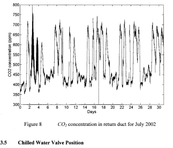
C02 Concentration and Ventilation Control Strate gy ... 26
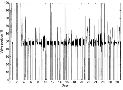
Chilled Water Valve Position ... 27
Fan Airflow Rate ... 28
2.3.6 Fan Airflow Rate ... 28
2.4 Sumrnary and Discussion ... 31
CHAPTER 3 VENTILATION CONTROL STRATEGY USING THE SUPPLY C02 3.1 3.2 3.2.1 3.2.2 3.2.3 3.2.4 3.2.5 3.3 3.4 3.5 3.5.1 3.5.2 3.6 3.6.1 3.6.2 3.6.3 3.7 CHAPTER4 4.1 4.2 4.2.1 4.2.1.1 4.2.1.2 4.2.2 4.2.3 4.2.3.1 4.2.3.2 4.2.4 4.2.4.1 4.2.4.2 4.3 4.4 4.5 CONCENTRATION SET POINT ... 32
Introduction ... 32
Ventilation Control Strategies ... 33
Fixed Minimum Outdoor Air Percentage (S1) ....•.•••••••...•..•..•...••.•..••...•••. 38
Fixed Minimum Outdoor Air Rate (S2) ... 39
COz-Based Demand-Controlled Ventilation (S3) ... 40
Multiple Space Equation (S4) ...•...•.•..•...•...•.... 41
Supply C02-Based Demand-Controlled Ventilation (S5) ...•...•... 43
Control Strate gy Optimization ... 4 7 Evaluation ofVentilation Control Strategies ... 47
Modeling Methodology ... 48
Modeling Strategy for AHU-6 System Evaluation ... 49
Modeling Strategy for AHU-4 System Evaluation ... 53
Evaluation Results ... 56
Results of Evaluation Based On Three Operating Conditions (MM-1) .. 56
Results of Evaluation Based On Real Monitored Data of AHU-6 system (MM-2) ... 59
Results of Evaluation Based On Weather Bin Temperature (MM-3) ... 63
Sumrnary and Discussion ... 69
MODELLING AND V ALIDA TION OF INVESTIGATED HV AC SYSTEM ... 71
Introduction ... 71
Modeling and Validation ofHVAC Components ... 72
Fan Model ... 72
Detailed Fan Model ... 73
Adaptive Fan Model ... 77
Damper Model ... 79
Cooling Coil and Valve Models ... 81
Detai1ed Cooling Co il Model. ... 82
Adaptive Cooling Coil Model ... 85
Chiller Model ... 87
Detailed Chiller model ... 87
Adaptive Chiller model ... 89
Duct Static Pressure Calculation ... 90
Load Prediction Tool. ... 92
4.6 Detailed and Adaptive V A V System Model ... 95
4.7 Summary and Discussion ... 98
CHAPTER 5 EVOLUTIONARY ALGORITMS FOR MULTI-OBJECTIVE 5.1 5.2 5.2.1 5.2.2 5.2.3 5.3 5.3.1 5.3.2 5.3.3 5.4 5.4.1 5.4.2 5.4.3 5.5 5.6 CHAPTER6 OPTIMIZATION IN HVAC SYSTEM CONTROL STRATEGY. ... 99
Introduction ... 99
Simplified V A V System Model ... 101
Fan Energy Use ... 101
Chiller Energy Use ... 1 02 Water Flow Rate Constraint ... 103
Problem Formation ... 103 Problem Variables ... 104 Objective Function ... 104 Constraints ... 105 Optimzation Algorithm ... 106 Genetic Algorithm ... 107
Comparison ofTwo-Objectve Optimzation Methods ... 108
Pareto-Optimal Solutions ... 108
Comparison Results and Algorithm Selected ... 109
Summary and Discussion ... 114
EVALUATION OF OPIMIZATION PROCESS ON EXISTING HVAC SYSTEM ... 116
6.1 Optimization Process ... 116
6.2 Zone Temperature Set Points ... 117
6.2.1 Optimization of Cri ti cal Zone Temperature ... 119
6.2.2 Optimization ofNon-Critical Zone Temperature ... 120
6.2.3 Number ofCritical Zones ... 120
6.3 Problem Formation ... 121
6.3.1 Problem Variables ... 121
6.3 .2 Objective Function ... 122
6.3.3 Constraints ... 122
6.4 Genetic Algorithm Optimization Method ... 123
6.5 Evaluation of the Optimization Process on AHU-6 System ... 124
6.5.1 Results of AHU-6 Evaluations ... 126
6.5.2 Discussion ofthe AHU-6 Evaluation Results ... 129
6.6 Evaluation of the Optimization Process on Modified HVAC System ... 135
6.7 Two-Objective Optimization and Daily Energy Use Control.. ... 136
6.8 Summary and Discussion ... 139
APPENDIXS ... 145 1. Manufacturer's Data ... ~ .... l45 2. Optimization ofHV AC Control System Strategy Using Two-Objective
Genetic Algorithm ... 149 3. Evaluation ofMulti-Objective Genetic Algorithm Optimization ... 164
Table I Table II Table III Table IV Table V Tble VI Table VII Table VIII Table IX Table X Table XI Table XII
Results of the evaluation based on three operating conditions ... 57
IAQ indexes for the investigated ventilation control strategies ... 67
Predicted mean vote (PMV) ... 94
Metric performance for investigated GA methods ... 111
Coefficients used in detailed fan model.. ... 146
Coefficient used in damper model. ... 146
Co il performance specification ... 14 7 PLR coefficient used in damper model ... 148
PLR coefficient presented in Equation 4.20 ... 148
PLR coefficient presented in Equation 4.21 ... 148
The zone characteristics of a modified HV AC system ... 152
Figure 1 Figure 2 Figure 3 Figure 4 Figure 5 Figure 6 Figure 7 Figure 8 Figure 9 Figure 10 Figure 11 Figure 12 Figure 13 Figure 14
Schematic of optimization process of on-line optimization of
supervisory control strate gy.... . . .. .... 5
Schematic of zones at second floor served by AHU -6 and AHU -4 units... .. .. . . .. . . .. ... 19
Schematic of AHU-6 or AHU-4 ofHVAC systems with the required measured variables... . . . .. ... .. .... .. .. 19
V A V box damper positions of AHU -6 for August 8 to 10, 2002... . . 24
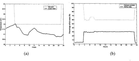
Zone temperatures (a), damper positions and of zone airflow ratios (b) when the supply air temperature is 15 °C for one day of August, 2002... 24
Zone temperatures (a), damper positions and of zone airflow ratios (b) when the supply air temperature is 13 °C for one day of August, 2002... ... ... ... ... ... ... ... .... .. ... ... ... ... 25
Mixing plenum static pressure when the outdoor damper is moved down from full position . . . ... 26
co2
concentration in retum duct for July 2002 ... 27Chilled water valve positions for July 2002 ... 28
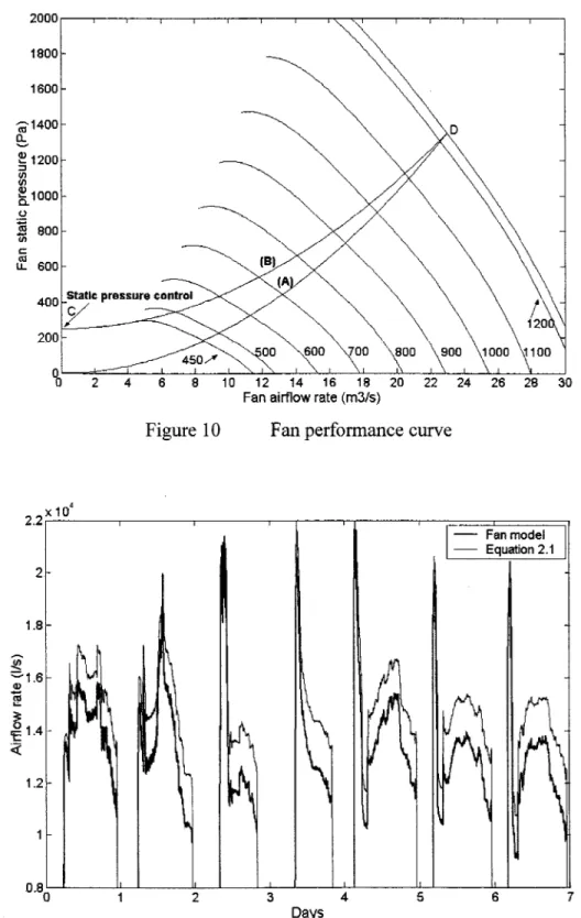
Fan performance curve... 30
Fan airflow rates determined by fan model and Equation 2.1 ... 30
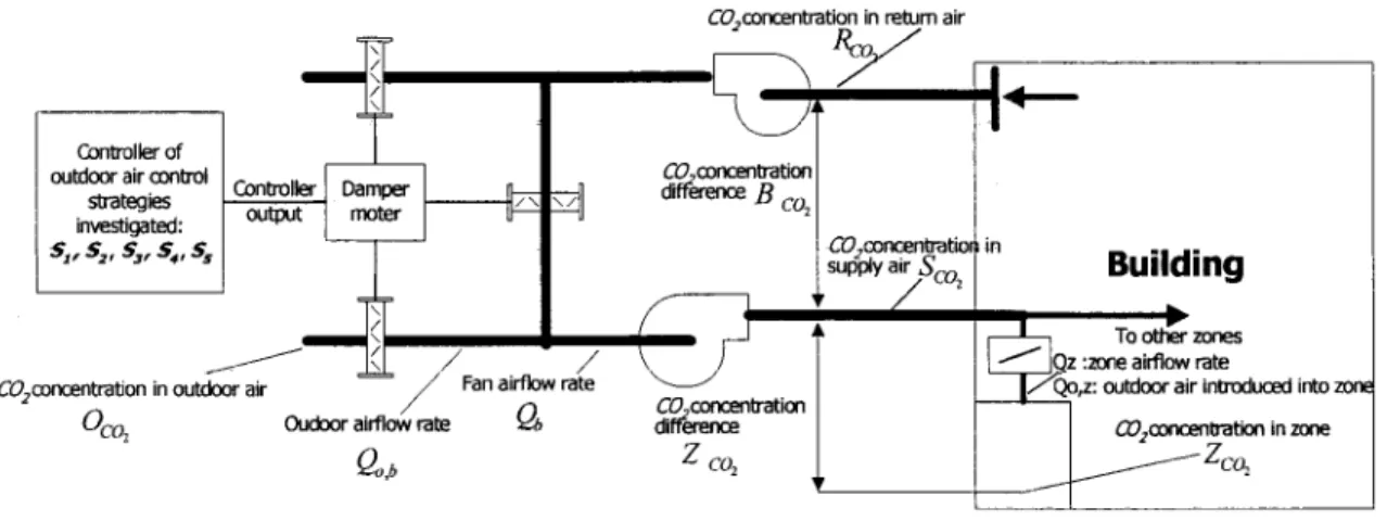
Sc hematie diagram of the AHU air distribution system for V A V system with the key points used .. .. .. .. .. .. .. .. .. .. .. .. .. .. .. .. .. .. .. .... ... 34
Investigated ventilation control strategies ... 38
Figure 15 Figure 16 Figure 17 Figure 18 Figure 19 Figure 20 Figure 21 Figure 22 Figure 23 Figure 24 Figure 25 Figure 26 Figure 27
Mode ling strate gy used for AHU-4 system evaluation 00 0 0 0 0 0 0 0 0 0 0 0 0 0 0 0 0 54 Building airflow and ventilation part-load ratios of AHU-6 for July 25 to 31, 2002oooooooooooooooooooooooooooooooooooooooooooooooooooooooooooooooooooooo 60 Outdoor airflow fractions of investigated strategies tested on AHU-6 for July 25 to 31, 2002oooOOoOOooOOOoOOOOOOoOOOoOOooOOooooooooooooooooooooooooooooo 60 Chiller energy demands of investigated strategies tested on AHU-6 for July 27 to 31, 2002ooooooooooooooooooooooooooooooooooooooooooOOoooOOooooooooooo 61
co2
concentration in the critical zones of investigated strategiestested on AHU-6 for July 25 to 31, 2002000 0 0 0 0 0 0 0 0 0 0 0 0 0 0 0 0 0 0 oooooOOooOO 0000000 62 Outdoor air fraction of investigated strategies for each Montreal bin temperature and when the Rv,b during the occupied period is 00600000000 64
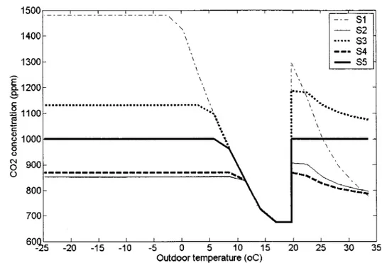
C02 concentration in the critical zones of investigated strategies for each Montreal bin temperature 0 0 0 0 0 0 0 0 0 0 0 0 0 0 0 0 0 0 0 0 0 0 0 0 0 0 0 0 0 0 0 0 0 0 0 0 0 0 0 0 0 0 0 0 0 0 0 0 0 0 64 Ratio of annual energy use of investigated strategies to reference
strate gy s3 0 0 0 0 0 0 0 0 0 0 0 0 0 0 0 0 0 0 0 0 0 0 0 0 0 0 0 0 0 0 0 0 0 0 0 0 0 0 0 0 0 0 0 0 0 0 0 0 0 0 0 0 0 0 0 0 0 0 0 0 0 0 0 0 0 0 0 0 0 0 68 The input and output variables of component models for validation purpose oooooooooooooooooooooooo 000000000000000000000000000000 ooooooooooooooooooooo 73 Comparison of the sum of measured zone airflow rates and fan
airflow rate obtained by fan model for July 25 to 31, 20020 0 0 0 0 0 0 0 oooooo 76 Comparison of airflow rates obtained through fan model and by
Equation 4.10 for July 29 to 31, 2002ooooooooooooooooooooooooooooooooooooooooooo 77 Energy demands obtained by artificial neural network and validated fan models 0 0 0 0 0 0 0 0 0 0 0 0 0 0 0 0 0 0 0 0 0 0 0 0 0 0 0 0 0 0 0 0 0 0 0 0 0 00 0 0 0 0 0 0 0 0 0 0 0 0 0 0 0 0 0 ooooooooo ooooooooo 79 Comparison of airflow rate obtained through fan model and damper model (damper wide open) for May 3-50 00 00 0 0 0 00 0 0 0 00 00 0 000 000 0 00 000000000 81
Figure 30 Figure 31 Figure 32 Figure 33 Figure 34 Figure 35 Figure 36 Figure 37 Figure 38 Figure 39 Figure 40 Figure 41
through CCDET, CCSIM, and MCCSIM models for July 29 ... 84 Comparison of supply air temperature obtained through detailed
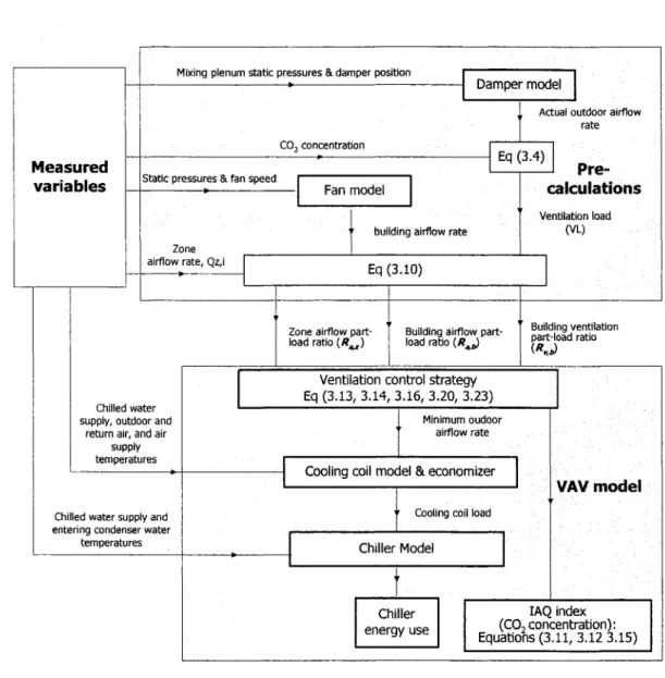
cooling co il models and neural network models . . . ... ... .. ... 87 Comparison of chiller energy demand obtained through detailed and adaptive chili er models . . . ... .... 90 Flow diagrams for V A V system performance calculations required by optimization process . . . 96 Optimal solutions obtained by NSGA after 100 generations for
case#1 ofHV AC problem ... 110 Optimal solutions obtained by NSGAII after 100 generations for
case#l ofHVAC problem ... 111 Search for optimal Pareto-optimal front in objective space using
NSGA-II when the initial solutions are not properly selected, and
with low probability of mutation . . . .. . . 112 Search for optimal supply air temperature (13°C) in decision space using NSGA-II, the crossover with low probability of mutation
operator cannot find real optimal solution... 113 Search for optimal Pareto-optimal front in objective spaces using
controlled NSGA-II when the initial solutions are not properly
selected, and with low probability of mutation . . . ... . . .. . . 114 Schematic of optimization process of on-line optimization of
supervisory control strate gy... . . . .. .. .. .. ... 118 Flow chart ofNSGA-II program ... 125 Feasible solutions obtained after 500 generations at 5:00P for July 25... ... 126 Actual and optimal energy demands for July 25 to 31, 2002... ... 127
Figure 44 Figure 45 Figure 46 Figure 47 Figure 48 Figure 49 Figure 50 Figure 51 Figure 52 Figure 53 Figure A2.1 Figure A2.2 Figure A2.3 Figure A2.4
Optimal and actual outdoor airflow rates for July 25 to 31... .... 128 Optimal and actual energy demands for two different days (26
February and 4 May)... 129 Computational effectiveness of the algorithm in finding optimal
solutions . . . ... ... . . .. . . ... 130 Optimal zone temperature set points for critical and other zones for three da ys . . . .. . . .. 131 Optimal and actual fan airflow rate for February 26.. ... . . .. 132 Optimal and actual heating energy demand for February 26... ... 133 Actual and optimal energy demand at three 'minimum zone airflo"" rate constraints' and for July 29, 2002. ... . .. .. . .. . .. . .. . .. ... .. .... ... .. 134 Energy demand obtained for three investigated control strategy... .. 136 Optimal daily energy use obtained using the two-objective
selectîon tool ( curve k) and one-objective optimization ( curve J)
for modified HV AC system... 138 Optimal daily energy use obtained by two-objective selection tool ( curve k) and one-objective optimization ( curve J) for existing
AHU-6 ... 138 Ratio ofactual to design sensible loads for zones ... 154 Outdoor air temperature profile. . . 15 5 Optimal energy demand for A, B, and C control strategies ... 155 Ratio of optimal and design airflow rate of critical ventilation zone (Zl) for A, B, and C control strategies... 156
Figure A2.7 Optimal chilled water supply temperature set point for A, and B
control strategies... 157 Figure A2.8 Outdoor airflow rate for A, B, and C control strategies... 158 Figure A2.9 Reheat, fan, and chiller energy use for a period after 6:00PM when
the reheat is used... .. . . .. . . .. 160 Figure A2.1 0 Energy demand for similar and different individual zone
temperature set points (strategy D and A, respectively)... .. . . .. 161 Figure A3.1 Real coded NSGA with crossover probability Pc=0.9, distribution
index IJc =4, mutation probability Pm=0.04, and 50 generations ... . . . 175
Figure A3.2 Real coded NSGA-II with crossover probability Pc=0.9,
distribution index IJc =4, mutation probability Pm=0.04, and 50
generations
acr
ACHM AFM AHU-4 AHU-6c
c
Ccomp Cp CAP FT CCDET CC SIM COP d DCHM DFM DM L'lPcomp L'lP damperAdaptive value determined from the on-line data Adaptive chiller model
Fan model coefficients Adaptive fan model Existing air handling unit Existing air handling unit Fan model coefficients
co2
concentration difference between the retum and supply air, ppm Pressure drop coefficient in the duct where the outdoor damper is installedFlow coefficient of V A V damper Flow coefficient in components Specifie heat of air
Chiller capacity factor Detailed cooling coil model Simple cooling coil model Damper model coefficient
Coefficient of chiller performance Fan diameter, rn
Detailed Chiller model Detailed fan model Damper model
Static pressure drops in the cooling and heating coils, in the filter, and in the humidifier, Pa
~Pduct ~Psystem ~Pvalve ~Ts ER PLR ER FT T]f
'lm
T]c GA Ho Hs HVAC INVCCDET K L MCCSIM N Nb NNCCM NSGA NSGAII (J' shareSystem pressure drop valve authority, Pa Full flow valve pressure drop, Pa
Sampling time step
Adjustment to rated efficiency due to change in load calculated by Equation 4.19
Adjustment to rated efficiency due to environmental variables calculated by Equation 4.20
Shaft power dimensionless coefficient Motor efficiency
Distribution index Genetic algorithm Enthalpy of outdoor air
Enthalpy of air leaving the cooling coil Heating, ventilating, and air conditioning Inverse form of the detailed cooling co il model Inherent flow rate factor
Thermalload on the body
Modified simple cooling coil model Fan speed
Actual occupancy in the building
Adaptive cooling coil model based on the artificial neural network Non-dominated sorting genetic algorithm
Elitist non-dominated sorting genetic algorithm Number of occupants in each zone i,
Ov,cd Ov,h Pc PLR PLRr Pm PMV P operation PPD Ps,ran Ps,ran,dsg Ps,mix Ps,out Ps,sd Prated Pz <po <pin,c <pou,c <Dt
.
QcCooling coil valve position, % Heating coil valve position, % Crossover probability
Chiller part load ratio based on available capacity Chiller part load ratio based on rated capacity Mutation probability
Predicted mean vote
Chiller power draw at specified operating conditions, kW Predicted percentage of dissatisfied, %
Fan static pressure, Pa
Design fan static pressure, Pa Mixing plenum static pressure, Pa Outlet fan static pressure, Pa Supply duct static pressure, Pa
Rated chiller power draw at ARl conditions, kW Population size
Outdoor air relative humidity Retum air relative humidity
Inlet air cooling coil relative humidity Outlet air cooling coil relative humidity Flow dimensionless coefficient
Pressure head dimensionless coefficient Building or fan airflow rate, lis
0 -!,rate
.
Q fan Qo,b Qo,b,dsg Qo,= Qo,z,dsg,t Q=ma'\:.
Qz.max,ilig R Ra.b R . a,Z,I Rv,bLiquid flow rate at rating, Ils
Inherent liquid flow rate at rating, lis Fan airflow rate, lis
Design fan airflow rate, 1/s Outdoor airflow rate, 1/s
Amount of outdoor air to be introduced into who le building, Ils
Design amount of outdoor air to be introduced into who le building, lis
Amount of outdoor air to be introduced into each zone i, lis Design amount of outdoor air to be introduced into each zone i, lis Indoor sensible loads at each zone i
Totalload of the building Zone airflow rate, Ils
Airflow rate at zone i, lis Maximum airflow rate, lis
Maximum airflow rate based on design static pressure, lis Valve rangeability
The airflow part-load ratio of the building The airflow part-load ratio of the zone i C02 concentration at retum air duct, ppm
TBM Tcws Tz,i UAext U Aext, rating Uint Uint, rating VAV VL V out Vref Vz
Fixed minimum outdoor air rate ventilation control strategy C02- based demand-controlled ventilation
Multiple space equation ventilation control strategy Supply C02- based demand-controlled ventilation
Simulated binary crossover operator
co2
concentration of supply air, ppmco2
concentration set point of supply air, ppm Temperature balance methodEntering condenser water temperature, °C Outdoor air temperature, °C
Return air temperatures, °C
Supply air and water temperatures, °C Chilled water supply temperature, °C Temperature of zone i, °C
External (air) heat transfer coefficient
External (air) heat transfer coefficient at rating Internai (water) heat transfer coefficient
Internai (water) heat transfer coefficient at rating Variable air volume
Ventilation load Output values Reference values
Air velocity in zone, rnls Chili er energy use, kW Fan energy use, kW
Ws
x
x y z, sg,1 d .z
Zc02,th tShaft fan power, kW Total energy use, kW
Uncorrected fraction of outdoor ventilation air in the supply system Damper model coefficient
The fraction of outdoor air in supply system introduced into building The fraction of outdoor air in supply system introduced into building at design condition
The fraction of outdoor air introduced into zone i at design condition Ratio of the required outdoor air to the primary air in the cri ti cal zone Required threshold, ppm
Indoor C02 concentration, ppm
energy costs associated with the operation ofthe HVAC system. Computer-aided energy management techniques as well as rigorous applications of the variable air volume (VAV) concept were accepted as means of achieving an energy-efficient and comfortable building environment. Not all V AV systems are successful and efficient. Multiple factors contribute to this unfortunate situation, including the system control strategy. This lack of efficiency is due to the fact that they are not wide-interaction optimized.
Most existing HV AC system processes are optimized at the local loop level; for example, in the existing HV AC system investigated in this thesis, which is installed at the Montréal campus of the École de technologie supérieure (ÉTS), one of the most
advanced "intelligent buildings" in North America today, each local control of arr individual subsysfum is individually determined, thus leading to the poor performance.
The air supply temperature set point for this HV AC system is determined as a function of the outdoor air temperature and fan airflow rate, without taking into consideration other subsystems, such as supply duct static pressure and chilled water supply temperature set points. Decreasing the supply air temperature set point may result in a lower supply duct static pressure and fan energy. Zone reheats for the investigated HVAC system that are used on winter days - only when the zone temperatures and airflow rates fall to their minimum limits - are not optimized, given their interaction with other set points. Applying sorne reheat in the low-load zone (ventilation critical zone) could significantly reduce the system's outdoor air ventilation. The zone air temperature set points of the investigated system are kept constant in the comfort zone during occupied periods. However, a strategy using the optimization of the individual
zone air temperature set points combined with other controller set points during occupied periods could further reduce system energy use.
The quality of the air inside buildings and the associated energy use has been of growing significantly concem over the last 20 years. Many publications have discussed different ventilation control strategies. The COrbased demand-controlled ventilation (COrDCV)
is one of the strategies that could reduce energy use by reducing the unnecessary over-ventilation of buildings. The energy consumption reduction benefits derived through the use of this strate gy have been demonstrated for many different applications. When this strategy is applied for multiple spaces by detecting the
co2
concentration in retum air, poor air quality may result inside certain zones. To overcome this problem, ASHRAE Standard 62-2001 (ASHRAE 2001) proposes the multiple space equation (MSE), whichcorrects the fraction of outdoor ventilation air in a supply system in order to minimize energy use while maintaining a proper indoor air quality (IAQ) in all zones, including the critical one. Since the amount of outdoor air is based on the design number of occupants, this amount could be more than required by the actual number (off-design), and result in waste in energy use. The "supply COrbased demand-controlled ventilation" (S-COrDCV) technique proposed in this research paper is a compromise
between the MSE and the COrDCV, taking into account: (i) the actual occupancy of the building and (ii) the critical zone ventilation requirement. This proposed strategy allows the on-line control of the outdoor air in response to actual building occupancy (as in
C02-DCV) while ensuring the ventilation requirements of each individual zone,
including the critical zone (as in MSE).
Existing studies on the optimization of the controller set point have demonstrated that the performance of HV AC systems can be improved through optimized supervisory control strategies. Set points can be adjusted by the optimized supervisor to improve the operating efficiency. These studies did not address the interaction between all controller
set points, including zone temperatures and supply C02 concentration set points, using the two-objective optimization problem.
This thesis presents a system approach that takes into account wide system interactions involving reheat (or zone supply air temperature); zone air temperature, including supply air temperature; supply duct static pressure; chilled water supply temperature, and supply C02 concentration (or minimum outdoor ventilation) using two-objective optimization problem.
Problem Statement
The operation of heating, ventilating and air conditioning (HV AC) systems is a critical activity in terms of optimizing a building's energy consumption (and, hence, reducing costs), ensuring occupants' comfort, and preserving air quality. The operation of these systems in most of the 430,000 commercial and institutional buildings in Canada is suboptimal, resulting in energy losses of 15 to 30% and, consequently, greenhouse gas emissions (GHGs). One example of the deficient operation of HVAC systems is the simultaneous use of air conditioning and heating systems. The performance of HV AC systems can be improved through better supervisory control. Set points and operating modes for an HVAC system can be adjusted by the supervisor to maximize overall operating efficiency. The optimization process developed in this proposed research makes it possible to reduce a building's energy consumption, while maintaining air quality and ensuring occupant comfort.
Goals of the Research
The main objective of this research project is to develop an optimization process allowing the on-line optimization of the HVAC supervisory control strategy. This supervisor sends the optimal controller set points to local control loops. The set points, such as supply air temperature, zone temperatures, zone supply air temperature (zone reheat), duct static pressure, chilled water supply temperature, and supply co2
concentration (minimum airflow rate) are then the problem variables, while the thermal comfort and the energy use are the objective functions. The optimization process could use the developed and validated detailed component model which is based on detailed manufacturer data or the adaptive component models based on artificial neural networks. These two detailed and adaptive VAV models are developed and discussed. To that end, the following methodology is employed:
(i) Monitoring of the investigated existing HV AC system; (ii) Development of the new ventilation control strate gy; (iii) Modeling and validation ofHVAC components; (iv) Development of optimization algorithm;
(v) Development of proposed optimization process;
(vi) Validation of the developed optimization process on multi-zone HVAC systems.
Proposed Optimization Process
HVAC systems are typically controlled using a two-level control structure. The lower-level local-loop control of single set points is handled using an actuator. The upper control level, the supervisory control, specifies the set points and the modes of operation. For the investigated existing HV AC system at the ÉTS campus, the supervisor specifies the set points that are locally determined. For example, the air supply temperature set point for this system is determined as a function of outdoor temperature and airflow rate without taking into consideration the other subsystems, such as supply duct static pressure and chilled water supply temperature set points. Zone reheats are used on winter days only when the winter zone temperatures and airflow rates fall to their minimum limits. The air temperature set point of each zone is maintained at a constant value within the comfort range during occupied periods. Although the supply duct static pressure set point changes gradually from zero to a maximum value (250 Pa) when the system is started up, this maximum value is always
maintained at normal operation. The minimum outdoor damper position is maintained at a constant value in order to provide the required outdoor air ventilation. The chilled water supply temperature of the existing system is also constant at 7 .2°C. Since the se set points are determined at the local loop level rather than through global system optimization, the system does not perform at its full potential.
On-line measured data
1
1 Data aquisition tool
Outdoor
Optim ization process
1-:--l-~~ Load prediction tool 1
1 conditions Pred icted loads
________ ,
~---,,.---o"PÏ:ï;,-ï;aï:i"Oii-"Proïi"Fàïn---~,,*'-.... .,.. 1 Objective functions ... ..
{ VAV m odel
1 Two-objective ·:
···--. 1 Trialsetpoints genetic algorithm __ • .-'
... L---r----~:=-' ... -Figure 1 ---1---1
t
Set of solution 1 Optimal solution 1 selection tool Selected solution (optim ial set points),
Supervisory control strate gy Con tro lie r's
optimal set points
Controller 1 Controllerl
~
1 Controllerl
lsubsystem # ~ lsubsystem # 21 rubsystem # n 1
1
Schematic of optimization process of on-line optimization of supervisory control strategy
The performance of this HV AC system can be improved through the optimization of the supervisor control strategy. The "optimized supèrvisor" specifies the set points using the
optimization process as shown in Figure 1, which includes (i) the adaptive or detailed V A V model, (ii) the two-objective genetic algorithm optimization program, and (iii)
three main tools, namely, data acquisition, load prediction, and optimal solution selection tools. The data acquisition tool receives and processes the on-line measured data.
The load prediction tool predicts sensible indoor zone loads, the latent building load, and the ventilation load for the optimization period, using the on-line measured data of the previous one. Since a set of optimal solutions is obtained by using the two-objective optimization problem, the selection tool is used to select the appropriate solution in order to minimize daily energy use and decrease the peak energy demand. Each component of the optimization process is developed and discussed through dissertation content organized as shown in outline of thesis.
Contributions
The original contributions of this work can be summarized the follows:
• lmproving the performance of multi-zone HV AC systems using the optimization process proposed and developed in this work.
• Developing a new ventilation control strategy usmg the supply C02 concentration set point. This proposed strategy allows the on-line control of the outdoor air in response to actual building occupancy while ensuring the ventilation requirements of each individual zone, including the critical one. • Application of artificial intelligence (AI)-based methods to the HVAC system.
The component models based on artificial neural networks and genetic algorithm methods are developed. The advantage of AI methods is that they do not require any prior knowledge of specifie models to solve problems as is the case with traditional methods based on physical or statistical approaches.
• Evaluation of the performances of several multi-objective GA optimization methods on HV AC system problems. The parameters of selected multi-objective
GAs are adjusted in order to improve its performance on a HV AC system problem.
• Mode ling of V A V components using the artificial neural networks. The simplest network architectures that give the best accuracy are implemented. The detailed V A V models as well as the monitored data are used to learn and validate these artificial neural network models.
• Evaluation of the HVAC system performance based on monitored data. Operation and design deficiencies are detected through the monitoring-based evaluation. The necessity of the optimization process to overcome these operation deficiencies is explained and justified.
• Development of strategies of HV AC component model validations. The validation difficulties that are faced due to lack of required measured data are overcome by using these validation strategies.
Outline of the Thesis
The thesis is organized into six chapters. Chapter 1 provides a literature review on global and local optimal control studies. Chapter 2 describes the investigated HV AC system and presents the operational problems observed through the monitoring. The performance of the existing HV AC system is evaluated using monitored data; the chapter also looks at how the proposed optimization process could improve its performance. Chapter 3 introduces the proposed ventilation control strategy using a supply C02 concentration set point and shows how this strategy could be integrated into
the V A V model used in the optimization process. The detailed and adaptive component models are discussed in Chapter 4, where data acquisition and load prediction tools are also presented. Chapter 5 examines the candidate two-objective optimization methods and evaluates their performances in solving the HVAC system control strategy. Chapter 6 shows the simulation results of applying the proposed optimization process on the existing HV AC system.
Since the energy crisis of the 1970s, great efforts have been invested in minimizing the energy costs associated with the operation of the HV AC system. Computer-aided energy management techniques as well as rigorous applications of the variable air volume (VAY) concept came to be accepted as means of achieving an energy-efficient and comfortable building environment. Not all VAY systems are successful and efficient (Cappellin 1997; Linder and Dorgan 1997). Multiple factors contribute to this unfortunate situation, including system control strategy. Several studies have been reported how the optimization of system control strategy can improve the V A V system performance (ASHRAE 2003). In this chapter, the literature review focuses on the global and local optimization of system control strategy. Since the new ventilation control strate gy is also developed in this research, a comprehensive review of ventilation control strategy is discussed. The literature review presents the following (i) variable air volume system, (ii) global and local optimization of control system, (iii) ventilation control strategies, and (vi) optimization methods.
1.1 Variable Air Volume System
Variable air volume systems help to solve energy problems; it can save 20 to 30% in building costs over conventional constant air volume systems. V A V system can also reduce frrst costs by using smaller equipment such as fans, pumps, boilers, chillers and less costly ductwork and piping distribution systems. V A V systems are described in several HVAC system reference books (Wendes 1991; Kreider and Rabl1994; Chen and Demster 1995; McQuiston, Parker, and Spitler 2000; Wang 2000). A VAY system controls temperature in a space by varying the quantity of supply air rather than varying the supply air temperature. A VAY terminal deviee at the zone varies the quantity of
supply air to the space. The supply air temperature is held relatively constant, depending on the season. V A V systems can be applied to interior or perimeter zones, with common or separate fans, with common or separate air temperature control, and with and without auxiliary heating deviees (ASHRAE 2003). The greatest energy saving associated with V A V occurs at the perimeter zones, where variations in solar load and outside temperature allow the supply air quantity to be reduced. Humidity control is a potential problem with V A V. If humidity is cri ti cal, as in certain research and development laboratories, process work, etc., systems may have to be limited to constant volume airflow. Not all V A V systems are successful and work efficiently. Multiple factors contribute to this unfortunate situation (Cappellin 1997; Linder and Dogran 1997). One of these factors is the control systems and supervisory control strategies (ASHRAE 2003; Kreider and Rabl1994).
1.2 Optimization of HV AC System Control
The optimal control problem associated with HV AC systems may be thought of as having a two-level control structure. Lower levellocal-loop control of a single set point is provided by an actuator. The upper control level, supervisory control, specifies the set points and other modes of operation that are time dependent. Set points and operating modes can be adjusted by the supervisor to maximize the overall operating efficiency (ASHRAE 2003). The performance HV AC systems can be improved through better local-loop and supervisory control. At any given time, the HV AC system may be at different modes of operation and set points. However, one set of control set point and modes results in minimum power consumption. This optimal control point results from trade-offs between the energy consumption of different HVAC system components or processes. Chapter 41 of ASHRAE (2003) provides a detailed review of the literature focusing on the global and local optimization of system control strategy.
With a view of local set point of individual system, the supply air temperature set point is reset in purpose to reduce energy use. The benefits of the supply air temperature re set for HVAC systems are not universally accepted. Research has shown that increasing the supply air temperature set point saves both cooling and heating energy for constant-air-volume systems (ASHRAE 2003). For VAV systems, it is not beneficiai unless local tempering is required to prevent overcooling rooms served with non-zero minimum setting boxes. Another possible benefit of the supply air temperature set point is that the chiller evaporator temperature could possibly be elevated, with a corresponding improvement in chiller efficiency. In addition, the supply air temperature reset is accompanied by an increased fan energy penalty; it also impacts both the economizer cycle performance and the outdoor air distribution. Ke and Mumma (1997a) investigated the interactions between the supply air temperature reset and ventilation requirements, which dominate the determination of the optimum supply air temperature. This optimization concept simultaneously reduces energy consumption and meets ventilation requirements. The results showed that increasing the supply air temperature set point reduces the humidification energy corresponding to the reduction of the outdoor airflow, but increases the fan energy associated with the growth of the primary airflow. The supply air temperature reset may also have a reduction for the tempering energy partly due to decreasing the heat needed for overcooled spaces, but mainly due to shifting heating loads from the V A V boxes to the system heating coils. Besides, the supply air temperature re set can save cooling energy by reducing reheat of the cold primary air and transferring cooling loads from the coils to the outdoor air as in the economizer cycle. Therefore, the supply air temperature reset will not save cooling energy much in the summer, but is good in mild seasons. However, the penalty of the fan power demand consumes all the benefits for the supply air temperature reset with the highest one. To take advantage of the conflict between the savings and penalty, optimization is the solution (Ke and Mumma 1997a). The optimum supply air temperature reset, most beneficiai in mild seasons, ensures that a system will operate in the valley of power demand curve.
The V A V system is based on the principle of matching the load by varying the air volume supplied to each zone rather than varying the temperature, with the intent of saving fan work energy as compared with a constant-volume system. As the individual V A V boxes modulate in response to zone demands, the total volumetrie flow rate will vary. If the fan air:flow is not controlled, the static pressure in the duct system will increase, resulting in noise, lack of control at the boxes, and possibility of duct blowout. The static pressure sensor located two-thirds to three-fourths of distance from the fan to the most remote box must be used to control the fan speed. Significant fan energy saving are possible if the static pressure set point is reset at least one of the V A V boxes remains open (ASHRAE 2003). With this approach, the flow resistance remains relatively constant. Complete building direct digital control DDC systems allow every box condition to be monitored, which allows the most demanding box to be identified at any time in the day' s operation and to be used for a signal (Haines and Wilson 1994 ). Several different strategies based on this concept are proposed in references (Hartman 1993; Warren and Norford 1993; Englander and Norford 1992). Englander and Norford (1992) used two methods of controlling the supply fan to minimize duct static pressure without sacrificing occupant comfort or adequate ventilation. Both methods make use of feedback from local zone flow control loops. Their technique forms the basis of the following reset strategy. At each decision interval (e.g., 5 minutes), the static pressure set point is increased by a fixed value if any of controller outputs for representative VAV box are greater than a threshold value. However, the static pressure set point is decreased by a fixed value if all of the controller outputs are less than a threshold value. Otherwise, the set point does not be changed. The set point between upper and lower is limited based on upper and lower limits and duct design.
A chiller plant consists of one or more chillers that are typically arranged in parallel with dedicated pumps to provide the primary source of cooling for the system. Individual feedback controllers adjust the cooling capacity of each chiller in order to maintain a specified chilled water supply temperature. Additional chiller control variables include
the number of chillers operating and the relative loading for each chiller. For a given total cooling requirement, individual chiller cooling loads can be controlled by utilizing different chilled water supply set points for constant individual flow or by adjusting individual flows for identical set points. The important aspect of operation mode is the sequencing of chillers and pumps. Sequencing defines the order and conditions associated with bringing equipment online or offline. Braun, et al (1989a) investigated the optimal control to chilled water systems without storage. The results showed that the best performance for different combination of chillers and fixed-speed pumps occurs at about 25% of design load with one chiller and pump operating. As the load increases, the system coefficient of performance (COP) decreases due to decreasing chiller COP and nonlinear increase in the power consumption of cooling tower and air handler fans. A second chiller should be brought online at the point where the overall COP of the system is the same with or without the chiller. For this system, this optimal switch point occurs at about 38% of the total design load or about 75% of the individual chiller's capacity. The optimal switch point for bringing a second condenser and chilled water pump online occurs at a much higher relative chilled load (0.62) than the switch point for adding or removing a chiller (0.38). However, pumps are typically sequenced with chillers (i.e., they are brought on-line together). In this case, the optimal switch point for bringing a second chiller online (with pumps) is about 50% of the overall design capacity of the individual chiller with dedicated pumps.
Individual feedback controllers adjust the cooling capacity of each chiller in order to maintain a specified chilled water supply temperature. One method for determining the optimal chilled water temperature described in (ASHARAE 2003) is to monitor the water control valve positions of "representative" air handlers. Since the valve position data may be unreliable, it should be monitored the discharge air temperatures as the following simple rules. Increase the chilled water set temperature if all water valves are unsaturated or the discharge air temperatures associated with all valves that are saturated are lower than set point. Decrease the chilled water temperature if more than one valve
is saturated at 100% open and their corresponding supply air temperatures are greater than their set points.
The global determination of optimum set points that minimize operating costs has been studied by (Cumali 1994; Braun, Klein, Mitchell, and Beckman 1989b; Cumali 1988). Curtiss, Brandemuehl, and Kreider ( 1994) used neural networks energy management program to perform on-line set point resets in an actual HV AC system. They found that this energy management system was able to maintain comfort and use less energy than a fixed set point. T o optimize the overall system performance, the system approach was utilized in optimal control strategies in a few studies: System-based optimal control and operation studies are examined by House and Smith (1995 and 1991). In House and Smith (1991), the optimal control strategy was applied to an HVAC system with a single zone. Energy saving of 49% was obtained. However, in House and Smith (1995), they proposed a system approach for optimizing multi-zone building systems respecting energy use and without sacrificing the thermal comfort. Energy saving of 24% was obtained.
A system approach was proposed for the on-line control strategy of HV AC in which multiple set points are optimized simultaneously in order to improve the system responses and reduce energy use (Wang and Jin 2000; Zheng and Zaheer-Uddin 1996; Zaheer-Uddin and Patel 1993). Wang and Jin (2000) presented a control strategy using a system approach based on predicting the responses of overall system environment and energy performance to changes of control settings of HV AC system. A genetic algorithm is used by the strategy to solve the optimization problem. The supply air temperature, chilled water temperature, and outdoor air ventilation were optimized. The simulation results of various weather conditions showed that energy saving could be obtained by this strategy while maintaining better thermal comfort.
The optimal control strategy based on steady-state models of HV AC system has been investigated by Zheng and Zaheer-Uddin (1996). These models are interconnected to simulate the responses of the V A V system. The studies based on system approaches showed that an optimal control strategy can improve the system responses and reduce energy use compared to the traditional control strategies (Zaheer-Uddin and Patel 1993, MacArthur and Woessner 1993).
1.3 Ventilation Control Strategy and Economizer Cycle
Air-side economizer cycle control reduces cooling costs when outside air conditions are suitable, that is, when the outdoor air is cool enough to be used as a cooling medium. There are two strategies of air-side economizer cycle control: temperature economizer control, and enthalpy economizer control. The economizer essentially consists of three dampers: an outdoor air damper, a recirculation damper, and a discharge damper. These three dampers are arranged so that the proportion of outdoor air may be modulated between a minimum value and 1 00 %. V arious strategies may be used to control the dampers. The conventional strategy is to couple all three dampers (Zhao 1998). Another strategy is to couple the outdoor air and recirculation dampers and leave the discharge clamper open at all operation conditions (Krakow, Zhao, and Muhsin 2000). Another strategy is to leave the outdoor air damper wide open (Seem, House, and Klaassen 1998). When the economizer is at minimum air mode, the outdoor airflow rate varies approximately in proportion to supply air quantity. That means the quantity of outdoor ventilation air supplied to the building at all part-load conditions, when in the minimum air mode, is below that needed to satisfy ASHRAE Standard 62-2001 (ASHRAE 2001). V arious ventilation control strategies may be used in variable air volume systems (Wang and Xu 2002; Elovitz 1995; Janu, Wenger, and Nesler 1995). Ke and Mumma (1999) presented eight ventilation control strategies and their annual energy and indoor air quality simulation results for an academie building as if it were situated in each of six geographie locations. The results showed that dynamic minimum outdoor air with
combined primary airflow and supply air temperature reset optimization is the best of reducing total energy consumption than the others (fixed minimum outdoor air percentage and rate, dynamic minimum outdoor air based upon the generalized multiple-spaces equation, etc.).
The COrbased demand-controlled ventilation (C02-DCV) is one of the strategies that could reduce energy use by reducing the unnecessary over-ventilation of buildings. This strategy is investigated in several studies (Alalawi and Krarti 2002; Persily 1993). The energy consumption reduction benefits derived through the use of this strategy have been demonstrated for many different applications (Schell 1998; Carpenter 1996). ASHRAE Standard 62-2001 (ASHRAE 2001) proposes the multiple space equation, which corrects the fraction of outdoor ventilation air in a supply system in order to minimize energy use while maintaining a proper indoor air quality (IAQ) in all zones, including the critical one. The multiple space equation has been discussed and implemented by several researchers (Kettler 2003; Ke and Mumma 1997b; and Mumma and Bolin 1994).
1.4 Genetic Algorithm
A genetic algorithm GA is a search procedure based on the mechanics of Darwin's natural selection. They combine survival of the fittest among string structures with a structured yet randomized information exchange to form a search algorithm with sorne of the innovative flair of human search (Bolland 1992). GA has been applied to a diverse range of scientific, engineering, and economie search problems (Goldberg 1989). Most of the initial research work can be found in various International Conference Proceedings. However, there exist now several textbooks on GAs (Gen and Cheng 2000; Vose 1999; Mitchell and Netlirary Inc, 1996; and Michalewicz, 1994). Examples of applications of GA in the science and engineering fields include optimization of neural network structure and weights, solution of optimal control problems, design of structures
and image feature recognition (Lee and Lam 1995; and Katz and Thrift 1994). The potential of GA for use in process control and control of air-conditioning systems has also been studied (Lam 1995; and Nordvik and Renders 1991). Lam (1995) found that classifier system with genetic algorithm was applicable to on-line computer control of air-conditioning systems and implementation of a self-learning control system. Huang and Lam (1997) optimized controller parameters for HVAC systems by using genetic algorithms, the results showed that the GA method yields a better performance than that of the traditional Ziegler-Nichols method for controller tuning. The GA is also used to design HVAC systems (Asiedu, Besant, and Gu, 2000; and Wright 1996). Wright (1996) described the performance of a simple genetic algorithm search method instead of using direct search optimization methods, it is concluded that the algorithm exhibits rapid initial progress but that final convergence is slow due to the highly constrained nature of the optimization problem. It is suggested that a more effective use of the constraint functions could improve the convergence and robustness of the algorithm. The performance of the algorithm is also sensitive to the problem formulation. Asiedu and robert (2000) used GA to design an HV AC air duct system with minimum !ife-cycle cost. Wright and Farmani (2001) investigated the simultaneous optimization of building fabric design, HV AC system size and the supervisory control strategy by using genetic algorithm search method, the results indicated that GA is effective in finding a feasible solution from an initial randomly generated population of solutions and exhibits rapid convergence on a solution.
The principles of multi-objective genetic algorithm optimization are different from that in a single-objective genetic algorithm optimization (Deb 2001). Many researchers have attempted to summarize the studies of multi-objective genetic algorithm optimization (Deb 2001; Veldhuizen and Lamont 1998; and Fonseca 1995). These reviews list many different techniques of multi-criterion optimization that exist to date. Wright and Loosemore (Wright and Loosemore 2001) investigated the application of a multi-objective genetic algorithm (MOGA) search method in the identification of the optimum