HAL Id: hal-01609112
https://hal.archives-ouvertes.fr/hal-01609112
Submitted on 6 Mar 2019
HAL is a multi-disciplinary open access
archive for the deposit and dissemination of
sci-entific research documents, whether they are
pub-lished or not. The documents may come from
teaching and research institutions in France or
abroad, or from public or private research centers.
L’archive ouverte pluridisciplinaire HAL, est
destinée au dépôt et à la diffusion de documents
scientifiques de niveau recherche, publiés ou non,
émanant des établissements d’enseignement et de
recherche français ou étrangers, des laboratoires
publics ou privés.
Determination of Thermal Contact Conductance in
Vacuum-Bagged Thermoplastic Prepreg Stacks Using
Infrared Thermography
Theo Baumard, Olivier de Almeida, Gary Menary, Yannick Le Maoult,
Fabrice Schmidt, Jérôme Bikard
To cite this version:
Theo Baumard, Olivier de Almeida, Gary Menary, Yannick Le Maoult, Fabrice Schmidt, et al..
Deter-mination of Thermal Contact Conductance in Vacuum-Bagged Thermoplastic Prepreg Stacks Using
Infrared Thermography. ESAFORM 2016 - PROCEEDINGS OF THE 19TH INTERNATIONAL
ESAFORM CONFERENCE ON MATERIAL FORMING, Apr 2016, Nantes, France. art. 110002- 6
p., �10.1063/1.4963511�. �hal-01609112�
Determination of Thermal Contact Conductance in
Vacuum-Bagged Thermoplastic Prepreg Stacks Using
Infrared Thermography
Théo Baumard
1, 2, a), Olivier De Almeida
1, Gary Menary
2, Yannick Le Maoult
1,
Fabrice Schmidt
1, Jérôme Bikard
31
Université de Toulouse ; CNRS, Mines Albi, INSA, UPS, ISAE ; ICA (Institut Clément Ader) ; Campus Jarlard, Route de Teillet, 81013 Albi, France
2School of Mechanical and Aerospace Engineering, Queen’s University Belfast ; Stranmillis Road, Belfast BT9
5AH, United Kingdom
3Rhodia- Solvay, Centre de Recherche et Innovation de Lyon ; 85, rue des Frères Perret, 69192 Saint-Fons, France a)Corresponding author: theo.baumard@mines-albi.fr
Abstract. The infrared heating of a vacuum-bagged, thermoplastic prepreg stack of glass/PA66 was studied to
investigate the influence of vacuum level on thermal contact resistance between plies. A higher vacuum level was shown experimentally to decrease the transverse heat transfer efficiency, indicating that considering only the effect of heat conduction at the plies interfaces is not sufficient to predict the temperature distribution. An inverse analysis was used to retrieve the contact resistance coefficients as a function of vacuum pressure.
INTRODUCTION
The use of thermoplastic composites has seen an important growth in the transportation sector in the past few years, partly thanks to shorter manufacturing time achievable compared to thermosetting composites. In order to reach the production rates required by the automotive industry, the processing techniques used such as thermoforming [1] must be optimized, for example by forming directly a non-consolidated stack. It is therefore critical to predict accurately the heat-up time and temperature distribution of the stack, given the effect on the mechanical properties of the final part [2]. The thermal contact resistances that exist in this case between the plies lower the heating efficiency and have to be carefully characterized.
Thermal contact resistance between composite prepreg stacks has been studied mainly in the frame of thermoplastic tape placement [3,4], or in an environment at ambient pressure [5]; it has been shown that an increase in compaction pressure leads to better heat transfer along the stack thanks to a better intimate contact between plies. Analytical models exist that allow the determination of thermal contact resistance as a function of applied pressure, for example through Hertzian contact theory [6]. However, the case in which the compaction pressure is generated by mean of a vacuum bag has not been investigated.
In the first part, an experimental campaign is conducted in order to investigate the effect of the partial vacuum pressure on the heating of a non-consolidated thermoplastic prepreg stack. Secondly, a numerical model is set up to determine a global thermal contact resistance coefficient through inverse analysis.
EXPERIMENTAL PROCEDURE
Material
The material used in this study is a commercially available 2/2 Twill glass/PA66 thermoplastic powder-impregnated prepreg, supplied by Rhodia - Solvay. The fabric has an areal density of 960g/m². Figure 1a shows the structure of the composite, i.e. glass fabric with high percentage coverage of polyamide droplets. The studied stack is composed of 6 plies, oriented in the same direction.
A surface roughness analysis was conducted using a confocal microscope profilometer. FIGURE 1. 1b shows the topography of a 48mmx5mm sample. Roughness parameters are presented in TABLE 1 1. They appear to be independent of the direction and the side of the fabric: the polyamide repartition can be considered homogeneous.
(a) Microscope image of the prepreg surface (b) Roughness analysis (top: topography, bottom: 3D representation)
FIGURE 1. Surface analysis of the prepreg
The specific heat capacity of the fabric was carried out using a Perkin Elmer DSC. Optical properties of the material were measured using a Bruker Vertex 70 FTIR spectrometer. Transmission and reflection measurements were carried out on 30x30mm samples randomly cut from the prepreg roll. All samples were shown to be opaque on the considered bandwidth, so the measured reflectivity directly relates to the emissivity of the samples.
The measured material properties relevant to the study are summed up in TABLE 1 1; the thermal conductivity values were evaluated in [7].
TABLE 1. Material properties
Properties 2/2 Twill Glass/PA66
Density ρ 960 g/m²
Transverse thermal conductivity κZ 0.53 W.m-1.K-1
Specific heat capacity Cp 1.02 J.g-1.K-1 (20°C), 1.11 J.g-1.K-1 (50°C)
Integrated emissivity ε 0.92
RMS roughness Rq 0.112mm ± 0.016mm
RMS slope of the roughness profile Rdq 137° ± 13°
Experimental Set-up
The experimental setup used to study the influence of the vacuum pressure is presented in Figure 2. The prepreg stack is bagged with a Capran 518/HS8171-6 polyamide film, and vacuum drawn with a CompositVac E25 pump. The stack is held vertically and heated with a horizontal 30cm long, 1000W halogen lamp from Toshiba Lighting, whose properties have been determined in previous studies [10]. The effect of pressure on heating is tested for two levels of relative pressure (-400mbar and -990mbar), successively and in that order to avoid effects arising from the possible plastic deformation of microscopic contact areas. The pressure level is controlled by mean of a variable leak valve.
FIGURE 2. Experimental set-up
The temperature field is measured on the back face of the stack using a CS 325 FLIR infrared camera [7.5-13.5µm], and recorded during the first 4000 seconds of the heating phase. The stack is then allowed to cool down to room temperature before vacuum level is modified.
EXPERIMENTAL RESULTS
An example of a measured back face temperature distribution is shown in Figure 3a, after 4000s at -400mbar. The lamp is oriented along the horizontal profile 3, and symmetrical with regard to vertical profile 4. The thermogram is symmetrical with regard to profile 4 as expected, but does not present a horizontal axis of symmetry. This can be explained by non-homogeneous convective effects around the vertically held stack.
Figure 3b shows the temperature variation versus time at the central point of the back face of the stack, for the two different considered relative vacuum levels. The graphs (green and red curves) show that varying the relative pressure from -400mbar to -990mbar leads to a temperature difference of 2.5°C after 4000s of heating. This means that even though compaction pressure is increasing, the heat transfer efficiency along the out-of-plane direction of the prepreg stack is reduced.
This result seems in contradiction with previous studies. This may imply that considering only the change in contact area between the plies is not sufficient to explain the observed effect (since contact conductance should increase with increasing compaction pressure).
Two competing effects are thus to be taken into account during the heating of a vacuum bagged prepreg stack to predict the temperature distribution: the vacuum pressure affects on one hand the conductive heat transfer through the polyamide droplets, but also impacts the conductive and convective heat transfer through the interstitial air. A possible explanation of the observed trend is the change in thermal conductivity of the interstitial air. The pressure variation is inversely proportional to the mean free path of molecules [12], which is related to thermal conductivity: the higher the distance between two molecular collisions, the lower the thermal conductivity.
Another possibility is the apparition of convective effects between the plies as the compaction pressure is decreased, considering that interstitial distance is large enough. The radiative transfer should also decrease with increasing compaction pressure, as the view factor depends on the effective contact area. However, given the range of temperatures reached inside the laminate, this mode of heat transfer should not be preponderant: the contribution of radiative transfer to thermal conductance is expected to be proportional to T3 [13]. The Stark number [11] gives the ratio of conductive heat transfer over radiative heat transfer: it is computed to be 65 in our case at 50°C. This confirms the fact that inter-ply radiative transfer is almost negligible.
(a) Back face temperature distribution after 4000s at -400mbar
(b) Temperature evolution of central point 5 for different vacuum levels
FIGURE 3. Results of the heating experiments
An additional experiment is presented in Figure 4: the vacuum level is changed dynamically during the heating phase, from -900mbar to -400mbar and back, and the temperature evolution of the central point (blue curve) is plotted against the previous curves at -990mbar and -400mbar (in black, moving averaged for clarity purposes). The effect on temperature is reversible: the curve shows no hysteresis (the deformation of the contact points in this pressure range can be considered as purely elastic) and no dynamic effect once the pressure is stable: the temperature change is due to the pressure level, rather than pressure variation rate. This implies that the effect is due mostly to the change of the interstitial fluid thermal properties, rather than convective effects.
NUMERICAL SIMULATION
The experimental setup is implemented in commercially available finite elements software COMSOL Multiphysics®. The halogen lamp is modelled as in a previous paper [7]: only the tungsten wire is considered as a cylindrical radiative source at a temperature T=1990 K (equivalent radius of the wire r=1.075mm), and the radiative
FIGURE 4. Evolution of temperature with dynamically varying vacuum level at
heat transfer is treated as a view factor problem, using the hemicube method [8]. The stack is modelled as 6 plies with homogenized properties as defined in Tab. 1.
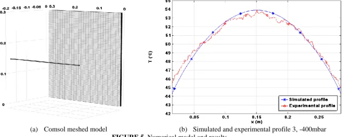
As a first approach, the contact conductance is evaluated in steady state regime. It is assumed to be constant at each inter-ply interface. A classical inverse analysis procedure allows its determination: an optimization routine, using the Nelder-Mead algorithm [9], is used to minimize the squared difference between the simulated and measured temperature on the horizontal central profile. Figure 5a presents the Comsol meshed model. After a mesh sensitivity analysis, the mesh is reduced to 30x60 elements on the surface, with 4 elements per ply through the thickness. The simulated profile for the optimized contact conductance is presented in Figure 5b for the case -400mbar.
(a) Comsol meshed model (b) Simulated and experimental profile 3, -400mbar
FIGURE 5. Numerical model and results
The numerical results are shown in Table 2. The order of magnitude of the measured contact conductances is coherent with values from the literature. Cassidy and Monaghan [5] reported thermal contact conductance ranging from 50 to 90W/(m².K), over a compaction pressure range of 0.2 to 0.8MPa for an APC/2 composite stack. Here, increasing the relative pressure from -990mbar to -400mbar leads to a 30% increase in contact thermal conductance.
TABLE 2. Contact conductance vs. relative pressure
Relative pressure p -990 mbar -400 mbar
Thermal contact conductance hglobal 78 W/(m².K) 102 W/(m².K)
CONCLUSIONS AND PERSPECTIVES
Thermal contact conductance in a vacuum-bagged, unconsolidated composite stack has been measured. Results presented show that the effect of decreasing the relative pressure inside the vacuum bag is to decrease the effective thermal conductivity of the stack, in apparent contradiction with previous results from the literature. The thermal contact conductance is decreased by 30%, over a relative pressure range of -990mbar to -400mbar. Two competing modes of heat transfer, namely conduction through surface asperities and conduction/convection from the interstitial air have to be taken into account to predict the temperature distribution in the stack. In terms of processing conditions, an optimum value of vacuum pressure can be found that maximizes the heat transfer along the stack. It is to be noted though that other parameters have to be taken into account (quality of impregnation …).
To further this work, a more comprehensive phenomenological model should be used in order to decouple the contributions of each mode of heat transfer at the plies interfaces. This study will be used as a part of a global, predictive simulation tool for the coupled heating and forming of thermoplastic composite parts.
ACKNOWLEDGMENTS
The work was conducted at Institut Clément Ader, Ecole des Mines d’Albi, France. The authors would like to thank Solvay for supporting this study and providing the testing materials.
REFERENCES
1. J. Throne, Understanding Thermoforming - 2nd Edition, Hanser Publications, 2008
2. M. D. Wakeman, L. Zingraff, P.-E. Bourban, J.-A. E. Manson, P. Blanchard, “Stamp forming of carbon fibre/PA12 composites – A comparison of a reactive impregnation process and a commingled yarn system”, Composites Science and Technology 66, 2006
3. A. Barasinski, A. Leygue, E. Soccard, A. Poitou, “An improvement in thermal modelling of automated tape placement process”, International conference on advances in materials and processing technologies (AMPT2010)
4. A. Levy, D. Heider, J. Tierney, J. Gillespie, “Inter-layer thermal contact resistance evolution with the degree of intimate contact in the processing of thermoplastic composite laminates”, Journal of Composite Materials 48(4), 2013
5. S. F. Cassidy, P. F. Monaghan, “Effect of contact resistances on the thermal conductivity of an unconsolidated fibre-reinforced thermoplastic prepreg stack”, Composites Manufacturing 5(4), 1994
6. B. B. Mikic, “Thermal contact conductance; theoretical considerations”, International Journal of Heat and Mass Transfer 17, 1974
7. A. El Bakali, O. De Almeida, J. Bikard, M. Villière, F. Schmidt, Y. Le Maoult, M. Dauphin, « Simulation of IR heating for composite stamping », Key Engineering Materials 554-557, 2013
8. M. F. Cohen, S. E. Chen, J. R. Wallace, D. P. Greenberg, “A progressive refinement approach to fast radiosity generation”, Computer Graphics 22(4), 1988
9. A. Nelder, R. Mead, “A simplex method for function minimization”, Computer Journal 7(4), 1965
10. S. Nakouzi, F. Berthet, D. Delaunay, Y. Le Maoult, F. Schmidt, V. Sobotka, “Optimization of the incident heat flux upon a 3D geometry composite part (Carbon/Epoxy)”, Key Engineering Materials 504-506, 2012 11. Q. Brewster, Thermal Radiative Transfer and Properties, Wiley and Sons, 1992
12. S.G. Jennings, « The mean free path in air », Journal of Aerosol Science 19(2), 1988
13. K. Y. Donaldson, B. D. Trandell, Y. Lu, D. P. H. Hasselman, “Effect of delamination on the transverse thermal conductivity of a SiC-fiber reinforced SiC-matrix composite”, Journal of American Ceramic Society 81(6), 1998