Pépite | Caractérisation de gaines de câbles électriques en incendie confiné au moyen d’un cône calorimètre à atmosphère contrôlée
248
0
0
Texte intégral
(2) Thèse de Sarah Chatenet, Université de Lille, 2019. A mon père A Norah. 2 © 2019 Tous droits réservés.. lilliad.univ-lille.fr.
(3) Thèse de Sarah Chatenet, Université de Lille, 2019. “ Ce n’est pas parce que les choses sont difficiles que nous n’osons pas, mais parce que nous n’osons pas qu’elles sont difficiles ” -. Sénèque. 3 © 2019 Tous droits réservés.. lilliad.univ-lille.fr.
(4) Thèse de Sarah Chatenet, Université de Lille, 2019. 4 © 2019 Tous droits réservés.. lilliad.univ-lille.fr.
(5) Thèse de Sarah Chatenet, Université de Lille, 2019. Aknowledgments Je tiens tout d’abord à remercier Gaëlle Fontaine et Serge Bourbigot qui m’ont ouvert la voie de l’incendie en 2015 en m’accueillant pour mon stage de fin d’étude, puis pour avoir dirigé cette thèse. Les échanges que l’on a pu avoir ont été très enrichissants sur le plan scientifique et leur vision m’a aidée à mener à bien ce projet. Leurs qualités humaines ont su instaurer un cadre de travail agréable. Ça a été un réel plaisir de travailler avec vous. Je remercie vivement Isabelle Flour pour m’avoir accueillie au sein du département MFEE d’EDF R&D durant ces trois années, ainsi que Laurent Gay pour avoir mis en place cette thèse et pour m’avoir fait confiance dans ce projet. Merci à Olivier Authier pour m’avoir suivie dans le cadre industriel tout au long de ces trois années. Son accessibilité, ses connaissances en génie des procédés et sa rigueur scientifique m’ont beaucoup apporté. Merci pour ta générosité. Je remercie Pascale Desgroux qui m’a fait l’honneur de présider mon jury de thèse, ainsi que Guillain Mauviel et Dhionis Dhima d’avoir accepté la fonction de rapporteur. Merci pour l’intérêt que vous avez porté à mon travail et pour nos échanges. Je remercie tout particulièrement les membres de l’équipe incendie à MFEE. En premier lieu Clément Cuperlier avec qui nous avons partagé beaucoup de temps sur l’installation expérimentale et qui, par ses qualités techniques et sa motivation, a permis de finaliser le programme expérimental et de le rendre aussi riche que possible. Merci à Maxime Lemesle pour m’avoir accueillie sur la boucle d’essais en début de thèse. Merci également à Romain Millerot pour avoir été présent pendant une partie des essais et pour avoir accepté de nettoyer l’ELPI un certain nombre de fois. Merci à Rémi Lang pour avoir prêté main forte quand il le fallait, toujours avec une petite blague. Merci à Sylvère Mongruel pour avoir apporté un certain nombre de solutions et s’être montré bien souvent rassurant. Merci à Sébastien Thion pour avoir suivi une partie de la thèse et pour toutes nos discussions. Cette thèse a bien fonctionné grâce à vous tous, un grand merci pour ça. Merci également aux agents que j’ai côtoyés au sein du département et à mes camarades doctorants. J’ai rencontré de belles personnes qui vont me manquer ! Pensée particulière à mon premier co-bureau qui est vite devenu un ami, et qui le restera encore de nombreuses années je l’espère.. 5 © 2019 Tous droits réservés.. lilliad.univ-lille.fr.
(6) Thèse de Sarah Chatenet, Université de Lille, 2019. Je tiens également à remercier les membres du laboratoire lillois R2F avec qui j’ai travaillé pendant mes visites régulières. Merci à Pierre Bachelet, Johan Sarrazin et Benjamin Dewailly d’avoir toujours été disponibles pour prêter main forte, et ce avec beaucoup de gentillesse. Merci également aux doctorants d’avoir été si accueillants et toujours partants pour partager un petit verre après le labo. Enfin, je tenais à remercier ma maman d’avoir été l’épaule si solide qui m’a toujours soutenue. Merci à mon papa qui m’a toujours fait croire que tout était à ma portée. Merci à Benjamin, celui qui partage ma vie. Je te suis reconnaissante d’être présent, de m’avoir soutenue et tant rassurée dans les moments de doute. Mes pensées vont enfin à ma fille Norah, qui, en voyant le jour à l’aube de la rédaction de ce manuscrit, a ouvert un nouveau chapitre de ma vie.. 6 © 2019 Tous droits réservés.. lilliad.univ-lille.fr.
(7) Thèse de Sarah Chatenet, Université de Lille, 2019. Table of contents Aknowledgments ............................................................................................................................................. 5 Table of contents ............................................................................................................................................. 7 Introduction ................................................................................................................................................... 11 Context .............................................................................................................................................................. 11 Aims .................................................................................................................................................................. 12 Chapter I: Bibliography................................................................................................................................... 15 1.. Introduction.............................................................................................................................................. 15 1.1. Generalities on polymer combustion .............................................................................................. 16 1.2. Molecular-scale and macro-scale polymer combustion ................................................................. 16. 2.. Molecular-scale polymer combustion ...................................................................................................... 18 2.1. Condensed phase reaction .............................................................................................................. 18 2.2. Gas phase reactions ........................................................................................................................ 23 2.3. Combustion of PMMA ..................................................................................................................... 27 2.4. Combustion of PVC .......................................................................................................................... 28. 3.. Polymer combustion at macro-scale ........................................................................................................ 30 3.1. Combustion efficiency convective and radiative components ....................................................... 30 3.2. Fire stages criteria ........................................................................................................................... 32 3.3. Effects of vitiation and equivalence ratio on combustion .............................................................. 34. 4.. Conclusion ................................................................................................................................................ 44. Chapter II: Controlled-atmosphere cone calorimeter set-up conception ........................................................ 45 1.. Bench-scale apparatus for fire testing ..................................................................................................... 45 1.1. Fire testing....................................................................................................................................... 45 1.2. Different types of flow-through bench-scale apparatuses for under ventilated conditions .......... 47 1.3. Conclusion on the comparison of the flow-through bench-scale apparatuses for under-ventilated conditions ..................................................................................................................................................... 53. 2.. Development of a new controlled-atmosphere cone calorimeter............................................................ 54 2.1. Context ............................................................................................................................................ 54 2.2. Design of the apparatus .................................................................................................................. 63 2.3. Controllers and sensors ................................................................................................................... 69 2.4. Equipment for smoke analysis ........................................................................................................ 71. 3.. Conclusion ................................................................................................................................................ 77. Chapter III: Representative material elaboration ........................................................................................... 79 1.. Introduction.............................................................................................................................................. 80. 2.. Materials and methods ............................................................................................................................ 82 2.1. Materials ......................................................................................................................................... 82 2.2. Elementary analysis ......................................................................................................................... 83 2.3. Thermal analysis .............................................................................................................................. 84 2.4. Optical measurement ...................................................................................................................... 85 2.5. Thermo-physical analysis ................................................................................................................ 86. 7 © 2019 Tous droits réservés.. lilliad.univ-lille.fr.
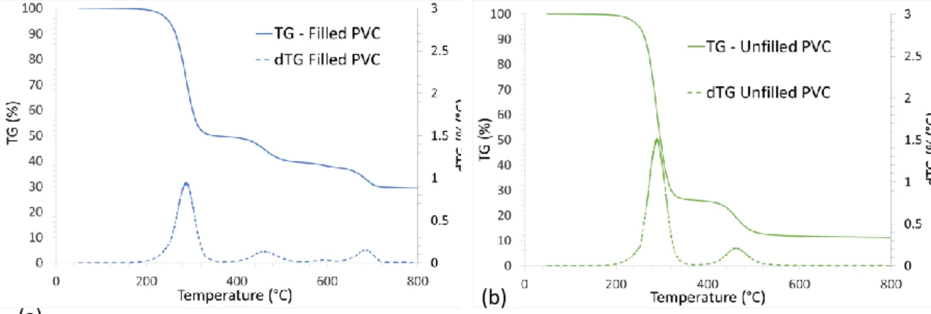
(8) Thèse de Sarah Chatenet, Université de Lille, 2019. 3.. Reverse engineering and characterization of electrical cable sheath ...................................................... 87 3.3. Industrial formulations for electrical cable sheath ......................................................................... 87 3.4. Composition analysis of the cable sheath ....................................................................................... 89 3.5. Thermal stability analysis ................................................................................................................ 92. 4.. Separate characterization of the main components of the electrical cable sheath ................................. 95 4.3. PVC cable sheath main components thermal stability and interactions ......................................... 95 4.4. Choice of stabilizing system ............................................................................................................ 98. 5.. Elaboration and characterization of representative and simplified materials ......................................... 99 5.1. Elaboration of PVC materials........................................................................................................... 99 5.2. Comparison of the reference material with the electrical cable sheath ....................................... 101 5.3. Characterization of filled and unfilled PVC properties for numerical simulation inputs ............... 102. 6.. Conclusion .............................................................................................................................................. 109. Chapter IV: Study of the under-ventilation effect ......................................................................................... 111 1.. Introduction............................................................................................................................................ 111. 2.. Data processing...................................................................................................................................... 112 2.1. Data acquisition ............................................................................................................................. 112 2.2. Data smoothing ............................................................................................................................. 113 2.3. Data presentation ......................................................................................................................... 113. 3.. Description of the experiments .............................................................................................................. 114. 4.. Well-ventilated experiments in the open configuration cone calorimeter............................................. 117 4.1. Mass loss and heat release rate measured with cone calorimeter in an open configuration ...... 118 4.2. Evolved gases measured with cone calorimeter in an open configuration .................................. 124 4.3. Evolved aerosols measured with cone calorimeter in an open configuration .............................. 126 4.4. Discussion on the well-ventilated fire parameters and combustion products ............................. 129. 5.. Under-ventilated experiments in the controlled-atmosphere cone calorimeter .................................... 131 5.1. Characterization of the fire regime ............................................................................................... 131 5.2. Influence of the confinement on the fire parameters .................................................................. 132 5.3. Influence of the confinement on evolved gases ........................................................................... 136 5.4. Influence of the confinement on evolved aerosols ....................................................................... 138 5.5. Discussion on the influence of the confinement on fire parameters and combustion products . 140. 6.. Conclusion .............................................................................................................................................. 142. Chapter V: Study of the vitiation effect ........................................................................................................ 145 1.. Introduction............................................................................................................................................ 145. 2.. Effect of vitiation on mass loss and heat release rate............................................................................ 146 2.1. Effect of vitiation on mass loss and heat release rate for PMMA ................................................. 146 2.2. Effect of vitiation on mass loss and heat release rate for unfilled PVC ......................................... 148 2.3. Effect of vitiation on mass loss and heat release rate for filled PVC ............................................. 151 2.4. Discussion on the effect of vitiation on the fire parameters ........................................................ 153. 3.. Effect of vitiation on the evolved gases ................................................................................................. 156 3.1. Effect of vitiation on the evolved gases for PMMA ....................................................................... 156 3.2. Effect of vitiation on the evolved gases for unfilled PVC .............................................................. 158 3.3. Effect of vitiation on the evolved gases for filled PVC .................................................................. 159. 4.. Effect of vitiation on the evolved aerosols ............................................................................................. 160 4.1. Effect of vitiation on the evolved aerosols for PMMA .................................................................. 160 4.2. Effect of vitiation on the evolved aerosols for unfilled PVC .......................................................... 161. 8 © 2019 Tous droits réservés.. lilliad.univ-lille.fr.
(9) Thèse de Sarah Chatenet, Université de Lille, 2019. 4.3. 5.. Effect of vitiation on the evolved aerosols for filled PVC .............................................................. 161. Conclusion .............................................................................................................................................. 163. General conclusion ....................................................................................................................................... 164 Conclusion ....................................................................................................................................................... 164 Perspectives .................................................................................................................................................... 165 Appendix ...................................................................................................................................................... 167 Appendix 1: Physical description of soot aggregates and theory of measurement ....................................... 169 1.. Physical description of soot aggregates ................................................................................................. 169 1.1. Brownian motion ........................................................................................................................... 169 1.2. Primary particles diameter Dp ....................................................................................................... 172 1.3. Radius of gyration Rg ..................................................................................................................... 172 1.4. Number of primary particles in the aggregate Np ......................................................................... 172 1.5. Expression of the fractal theory .................................................................................................... 172. 2.. Physical quantities useful for characterization ...................................................................................... 174 2.1. Information related to particles weight and volume .................................................................... 175 2.2. The equivalent diameters.............................................................................................................. 176. 3.. Theory of measurement ......................................................................................................................... 178. Appendix 2: Mass spectra of DIDP py-GC/MS ............................................................................................... 180 Appendix 3: Plaques processing details ........................................................................................................ 181 1.. Filled PVC plaques processing details ..................................................................................................... 181. 2.. Unfilled PVC plaques processing details ................................................................................................. 183. Appendix 4: Tests performed under air in open and confined configuration ................................................ 185 1.. Open configuration ................................................................................................................................ 185 1.1. Mass loss and HRR ......................................................................................................................... 185 1.2. Gases ............................................................................................................................................. 188 1.3. Aerosols ......................................................................................................................................... 192. 2.. Confined configuration........................................................................................................................... 194 2.1. Mass loss and heat release rate .................................................................................................... 194 2.2. Gases ............................................................................................................................................. 197 2.3. Aerosols ......................................................................................................................................... 200. Appendix 5: Tests performed in confined configuration under various oxygen contents ............................. 203 1.. Mass Loss and Heat Release Rate .......................................................................................................... 203 1.1. 18 vol. %O2 .................................................................................................................................... 203 1.2. 16 vol. %O2 .................................................................................................................................... 206 1.3. 13 vol. %O2 .................................................................................................................................... 209 1.4. 9 vol. %O2 ...................................................................................................................................... 210 1.5. 6 vol. %O2 ...................................................................................................................................... 212 1.6. 2 vol. %O2 ...................................................................................................................................... 214. 2.. Gases ...................................................................................................................................................... 216 2.1. 18 vol. %O2 .................................................................................................................................... 216 2.2. 16 vol. %O2 .................................................................................................................................... 220. 9 © 2019 Tous droits réservés.. lilliad.univ-lille.fr.
(10) Thèse de Sarah Chatenet, Université de Lille, 2019. 2.3. 2.4. 2.5. 3.. 9 vol. %O2 ...................................................................................................................................... 224 6 vol. %O2 ...................................................................................................................................... 227 2 vol. %O2 ...................................................................................................................................... 231. Aerosols .................................................................................................................................................. 235 3.1. 18 vol. %O2 .................................................................................................................................... 235 3.2. 16 vol. %O2 .................................................................................................................................... 236. References ................................................................................................................................................... 239. 10 © 2019 Tous droits réservés.. lilliad.univ-lille.fr.
(11) Thèse de Sarah Chatenet, Université de Lille, 2019. Introduction Context In the nuclear industry for power generation, fire is the most frequent internal aggression with an occurrence of one fire outbreak per year and per nuclear unit in France. A fire is threatening by two means: the heat it releases that may drive a fire growth and the smoke it yields, composed of potentially toxic and/or corrosive gases and aerosols that may be transported away from the seat of the fire and interact with electrical components in the area. The fire incident in the Nogent-sur-Seine nuclear power plant (NPP) on July 2018 that caused a nuclear reactor to lose its power supply, without impacts to persons and the environment, can be mentioned. In NPPs, compartments in the buildings are generally sealed from one to another while connected to a ventilation network. This ventilation system provides a suitable pressure cascade to prevent any accidental radioactive leak within the compartment from escaping to the open atmosphere. The compartments where radioactive materials are present are under-pressurized and the outgoing air flows are gathered and filtered thanks to high-efficiency air-cleaning devices [1]. As flaming fires consume the oxygen, this low ventilation level drives confined fires in oxygen depleted conditions (i.e. [O2] < 21 vol. %) at advanced stages. As NPPs can require more than 1 600 km of electrical cable, electrical cable sheaths are the most abundant fire load in these premises [2]. The study of electrical cable sheath material fire behavior is then a first attempt at covering the fire impact in NPPs. In all the running NPPs, i.e. second generation NPPs, electrical cable sheaths are mainly PVC1-based formulated materials whereas in the next generation NPPs, i.e. third generation, electrical cable sheaths are mainly non-halogenated EVA/ATH2 materials. In 2014, Electricité de France (EDF) was required by the nuclear safety authority (ASN) to study specifically the impacts of NPP fire effluents on the electrical equipment necessary to the nuclear safety [3]. For this reason, a Research and Development (R&D) unit of EDF Lab Chatou3 develops indepth knowledge on the consequences that might have NPP-type fires by combining an experimental and a numerical approach. The experimental studies are particularly crucial in the fire science field, especially when the burning fuel is as complex as formulated polymeric materials. A bench-scale apparatus allowing to characterize simultaneously the fire parameters, i.e. heat release rate (HRR) and mass loss rate (MLR), and the effluents, i.e. the light gases and the aerosols, by coupling a mass loss. 1. Polyvynil chloride Ethylene-co-vynil acetate flame retarded with aluminium trihydroxide 3 Fluids Dynamics, Power Generation and Environment department (MFEE) 2. 11 © 2019 Tous droits réservés.. lilliad.univ-lille.fr.
(12) Thèse de Sarah Chatenet, Université de Lille, 2019. cone to a Fourier Transformed Infrared spectrometer (FTIR) and to an Electrical Low-pressure Impactor granulometer (ELPI) was developed during a former PhD work [4]. This apparatus permits to study well-ventilated fires in air that can be assimilated to the early fire stages in NPP. This work was focused on the non-halogenated electrical cable sheaths. At the same time, a lack of data concerning the PVCbased electrical cable sheaths fire behavior remains. Moreover, oxygen depleted, i.e. under-ventilated and vitiated fires4, have to be considered to study the whole fire scenario.. Aims In this context, this PhD project is initiated through a collaboration with the Materials and Transformation Unit (UMET) of the Ecole Nationale Supérieure de Chimie de Lille (ENSCL) to adapt this bench-scale apparatus to oxygen depleted studies and to investigate the fire behavior of electrical cable sheath at different fire stages. The output of this new controlled-atmosphere cone calorimeter is firstly compared with the literature by performing experiments with PMMA5, as it is a widely studied material in fire science [5]. Then, an industrial PVC-based electrical cable sheath material is submitted to a reverse engineering to disclose its formulation in the aim at elaborating a representative material of controlled composition and shape. This material, in the form of plaque, is then tested in the controlled-atmosphere cone calorimeter (air/nitrogen mixture) under constant radiative heat flux (50 kW.m-2) in well-ventilated, under-ventilated and vitiated conditions. In order to describe more specifically each step of this PhD work, this document is divided into five chapters as follows. The first chapter gathers a theoretical background on polymer thermal decomposition mechanism and on both gaseous and aerosols formation mechanisms, especially soot particles. Some pieces of fundamental information on the oxygen depleted fire science are approached and, finally, a state of the art on the oxygen depleted fire studies at bench-scale is proposed to position this present work among the literature. The second chapter presents the conception of the new controlled-atmosphere cone calorimeter. It is compared with the existing benches in the literature that are dedicated to the same studies in confined atmosphere. The technical features are detailed, as well as the analytical equipment aiming at characterizing fire parameters and evolved smoke effluents throughout the material thermal decomposition. The third chapter is dedicated to the PVC-based electrical cable sheath reverse engineering and to the formulation and characterization of the representative material. Two formulations are developed: the. 4. Under-ventilated regime corresponds to fuel-to-air equivalence ratio > 1, and vitiated regime is defined by [O2] < 21 vol. % at the inlet gas stream. 5 Polymethylmethacrylate. 12 © 2019 Tous droits réservés.. lilliad.univ-lille.fr.
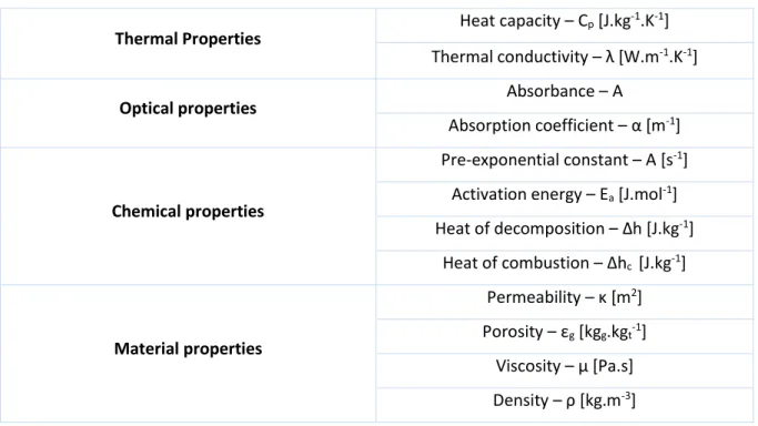
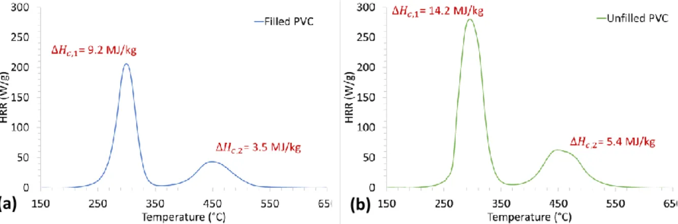
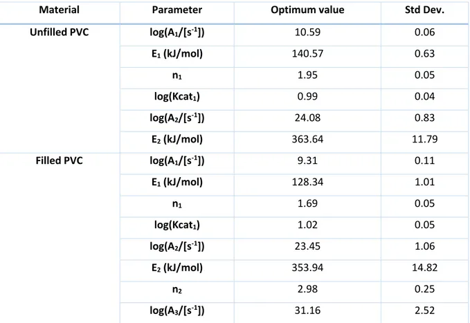
(13) Thèse de Sarah Chatenet, Université de Lille, 2019. first one (PVC with mineral filler, i.e. filled PVC) used as the representative material, and the second one (PVC without mineral filler, i.e. unfilled PVC). The unfilled PVC material is developed in order to perform tests in the cone calorimeter with a simpler fuel and thus bridge the gap towards the comprehension of the fire behavior phenomena occurring during the experiments with the representative material. Each main component of the representative material is tested at lab-scale in terms of thermal stability and thermal decomposition mechanism to identify the effect of temperature in controlled and homogeneous conditions. Also, thermo-physical properties of interest in fire science, e.g. thermal conductivity and heat capacity, are characterized for both of filled and unfilled PVC materials. The fourth chapter deals with the effect of ventilation on the fire parameters and on the smoke effluents. The results of well-ventilated and under-ventilated experiments at 21 vol. % O2 in the inlet gas stream with PMMA, representative material, i.e. filled PVC and unfilled PVC, are presented and discussed and the differences observed between the two conditions are highlighted. The fifth chapter relates the study of the effect of vitiation in under-ventilated conditions on the fire parameters and on the smoke effluents for PMMA, filled and unfilled PVC. Varying the oxygen content from 2 vol. % to 21 vol. % allows to investigate its effect in flaming and non-flaming regime. The observed influence of the oxygen content is highlighted for each material and is compared between the materials. Finally, a conclusion to this PhD work and some perspectives are suggested.. 13 © 2019 Tous droits réservés.. lilliad.univ-lille.fr.
(14) Thèse de Sarah Chatenet, Université de Lille, 2019. 14 © 2019 Tous droits réservés.. lilliad.univ-lille.fr.
(15) Thèse de Sarah Chatenet, Université de Lille, 2019. Chapter I: Bibliography. Chapter I: Bibliography 1.. Introduction. 15. 1.1.. Generalities on polymer combustion. 16. 1.2.. Molecular-scale and macro-scale polymer combustion. 16. 2.. Molecular-scale polymer combustion. 18. 2.1. Condensed phase reaction 2.1.1. Heating 2.1.2. Anaerobic pyrolytic decomposition 2.1.3. Thermo-oxidative decomposition 2.1.4. Char formation. 18 19 19 22 22. 2.2. Gas phase reactions 2.2.1. Flame reactions 2.2.2. Soot particles formation. 23 23 24. 2.3.. Combustion of PMMA. 27. 2.4.. Combustion of PVC. 28. 3.. Polymer combustion at macro-scale. 30. 3.1.. Combustion efficiency convective and radiative components. 30. 3.2.. Fire stages criteria. 32. 3.3. Effects of vitiation and equivalence ratio on combustion 3.3.1. Effect of equivalence ratio on combustion products 3.3.2. Effect of vitiation on fuel mass loss rate 3.3.3. Oxygen depleted fire studies: a state of the art 4.. Conclusion. 34 34 36 38 44. 1. Introduction Since the three materials of interest in this work, i.e. PMMA, unfilled PVC and filled PVC, are polymeric materials, it is essential to understand the polymeric materials reaction to fire. For this purpose, the polymer combustion phenomena are first described at a molecular scale, which permits to present the thermal decomposition mechanisms and the evolved gaseous and aerosols species taking part in the combustion in the gas phase. In a second time, since fire is a complex and coupled physical phenomenon, some fundamentals on the combustion phenomena at a macro-scale are presented and the effect of oxygen concentration is specifically detailed.. 15 © 2019 Tous droits réservés.. lilliad.univ-lille.fr.
(16) Thèse de Sarah Chatenet, Université de Lille, 2019. Chapter I: Bibliography. 1.1.. Generalities on polymer combustion. When the polymer undergoes a sufficient thermal stress, it heats up and its chemical bonds start to break. This phenomenon is the thermal decomposition or pyrolysis. Pyrolysis leads to different compounds: solids, liquids and volatiles. Among the volatile compounds, some are non-combustible (H2O, CO2), but some are combustible (low molecular weight organic compounds such as CH4, C2H4…) with the potential of releasing heat by their combustion reaction. They form with air (the combustive) an inflammable gas phase. Two scenarios may happen: in one case, an external energy source (such a flame, a spark, an incandescent particle…) ignites this combustible/combustive mixture or in the second case, the self-ignition temperature is reached because of the exothermic chemical oxidation reactions and a spontaneous ignition happens. At the ignition, the combustion takes place and the flame produces a heat flux that can be sufficient to sustain the thermal decomposition and, as a result, produce more combustible gases. In this way, fire is a self-sustained phenomenon. The combustion is maintained as long as there is enough energy transferred to the polymer surface to sustain its thermal decomposition. Polymer thermal decomposition may proceed by heat alone, or by the combined action of heat and oxygen. In many polymers, thermal decomposition processes are accelerated by the action of oxygen, lowering the minimum decomposition temperatures [6]. Prior to ignition, thermo-oxidative decomposition results in aerobic pyrolysis of fuel and other species. After ignition, during flaming, even in well-ventilated conditions, pyrolysis of the condensed phase is essentially anaerobic, with all the oxidation taking place in the gas phase [7]. Thus, the mass loss or the residue formation, resulting from pyrolysis, corresponds to a decomposition of the material in an inert atmosphere [8]. Thermo-oxidative decomposition will then be present during a fire only for non-intense flaming and non-flaming samples or near and after extinction. Furthermore, the observation of bubbles of volatile fuel in decomposing polymers around the time to ignition showed that for many thermoplastics, even prior to ignition, most volatile formation comes from the bulk of the polymer rather than its surface which makes the critical decomposition condition remain anaerobic [9].. 1.2.. Molecular-scale and macro-scale polymer combustion. When studying fire at a molecular-scale, three stages can be identified and separated: the heating stage, the decomposition stage and the oxidation stage. Each of these three stages are detailed in Table 1. When studying fire at a macro-scale, there are a higher amount of stages to consider. Five stages are listed and described in Table 2: the heating stage, the pyrolysis stage, the ignition stage, the flame spread and the fire development.. 16 © 2019 Tous droits réservés.. lilliad.univ-lille.fr.
(17) Thèse de Sarah Chatenet, Université de Lille, 2019. Chapter I: Bibliography The heating stage at the molecular-scale depends on the intrinsic chemical and physical properties of the material whereas at the macro-scale, it takes into account shape factors, e.g. the thickness. The study of the decomposition stage at the molecular-scale is focused on the polymer thermal decomposition mechanisms whereas at the macro-scale, the gaseous compounds diffusion inside the polymer from the bulk to the surface is considered. The oxidation stage at molecular-scale describes the combustion chemical reactions whereas the ignition stage at macro-scale considers the flame radiative feedback to the fuel surface that will furtherly decompose and yields combustible gaseous compounds to the flame. The flame spread stage, resulting from the adjacent materials pyrolysis under the flame increasing heat flux and the fire development stage due to an increase in the materials burning are only considered at the macro-scale. As illustrated by the confrontation of Table 1 and Table 2, the molecular-scale is necessary to understand the implied mechanisms, but since a lot of physical events are coupled during a fire, the study of the macro-scale is essential. Table 1: Stages of combustion at a molecular scale [6]. The molecular scale Stage 1. Heating. An external heat source supplies heat causing the temperature of the polymer to increase. The extent of temperature change depends on the specific heat of the material. Physical, mechanical, and thermal properties change.. Stage 2. Decomposition. At high temperatures, the majority of the bonds reach failure points, causing the release of gaseous molecules dependent on the nature of the material burning. This can be accelerated by attack of oxygen on the polymer surface.. Stage 3. Oxidation. In the presence of oxygen at high temperatures, oxidation of the gaseous fragments proceeds rapidly, releasing heat and combustion products.. 17 © 2019 Tous droits réservés.. lilliad.univ-lille.fr.
(18) Thèse de Sarah Chatenet, Université de Lille, 2019. Chapter I: Bibliography Table 2: Stages of combustion at a macro scale [6]. The macro scale Stage 1. Heating. Heat causes a temperature rise which will depend on the thermal inertia of the material.. Stage 2. Pyrolysis. Heat causes decomposition of the fuel, followed by pyrolysis of fuel to the gas phase.. Stage 3. Ignition. Fuel accumulates above the surface, and reacts with oxygen. Once the critical concentration of free radicals is reached, flashing will occur. When the total heat flux to the surface from the fuel oxidation is sufficient to pyrolyze enough fuel to replace it, ignition will occur, the rate of reaction will increase and produce carbon dioxide and water.. Stage 4. Flame spread. As the radiant heat flux increases, it will pyrolyze adjacent materials, leading to a repeated series of ignition, resulting in fire growth.. Stage 5. Fire. As the flame gets larger, it will no longer be able to entrain sufficient. development. oxygen, and products of incomplete combustion such as carbon monoxide and soot will be produced, increasing the radiative component of heat transfer.. 2. Molecular-scale polymer combustion Considering phenomena at molecular scale allows to decouple the physical phenomena. In this section, the reactions happening in the condensed phase are describe in a first part. In a second part, the reactions happening in the gas phase are presented.. 2.1.. Condensed phase reaction. There are two categories of polymers: thermoplastics and thermosets. Thermosets have additional covalent bonds forming crosslinkages between the polymer chains resulting in a 3-D network. This network gives the thermosets a particular reaction to thermal stress, preventing the polymer from softening and flowing. Thermosets are not studied in the scope of this literature review. Indeed, PMMA and PVC are thermoplastic polymers. They are constituted of independent polymer chains tangled-up together, which confers the material cohesion. The thermoplastics condensed phase reactions upon heating are described in the following section.. 18 © 2019 Tous droits réservés.. lilliad.univ-lille.fr.
(19) Thèse de Sarah Chatenet, Université de Lille, 2019. Chapter I: Bibliography. 2.1.1. Heating There are two categories of thermoplastic polymers: amorphous and semi-crystalline. The physical behavior of a thermoplastic under heat depends on its degree of crystallinity. Under heat, thermoplastics soften, melt (only the crystalline parts), then flow. Amorphous polymers stay at the solid state, they transform from glass state (T<Tg) to rubber state (T>Tg), then to a viscous state (T<Td) by flowing6. The crystalline part of semi-crystalline polymers transforms from rubber state to liquid state at T=Tf and their amorphous part undergo the same transformation as amorphous polymers.. 2.1.2. Anaerobic pyrolytic decomposition Thermal decomposition is an endothermic process. An energy higher than the chemical bonds energy is needed to break the chemical bonds present in the macromolecule. The required amount of energy to heat up the polymer to the decomposition temperature is about 1 to 2 kJ.g-1 [10]. There are numerous thermal decomposition mechanisms that depend on the chemical bonds nature, the polymer structure and the presence of oxygen. In the absence of oxygen, thermal decomposition is only due to the action of heat and only anaerobic pyrolytic reactions occur. Anaerobic pyrolytic decomposition of polymers is mainly a free radical process concerning whether the polymer backbone, the pending groups, or both. There are four anaerobic pyrolytic decomposition mechanisms, depending on the polymer structure, that can lead the organic polymer to decompose into volatile products: -. Random chain scission;. -. End-chain scission or unzipping;. -. Chain stripping;. -. Cross-linking.. These four pyrolytic decomposition mechanisms are detailed in the following paragraphs. 2.1.2.1.. Random chain scission. Random chain scission usually takes place when the bonding energies are similar along the chain. This mechanism is observed for a large amount of thermoplastics (PE7, PP8, PET9, PA6610…) and leads to a decrease of the polymer molecular weight by the formation of a large range of molecular weight molecules. Some oligomers are small enough to volatilize without any further decomposition. This. 6. Tg, Td and Tf are the glass transition temperature, the decomposition temperature and the fusion temperature respectively. 7 Polyethylene 8 Polypropylene 9 Polyethylene terephtalate 10 Polyamide 6-6. 19 © 2019 Tous droits réservés.. lilliad.univ-lille.fr.
(20) Thèse de Sarah Chatenet, Université de Lille, 2019. Chapter I: Bibliography process implies multiple steps free radical reactions: the initiation step (random or end-chain), the propagation step (intra- or inter-molecular hydrogen transfer or depolymerization) and termination (unimolecular termination, recombination, and dismutation) [11]. 2.1.2.2.. End-chain scission or unzipping. End-chain scission or unzipping corresponds to polymer backbone specific points breaking, generally at the end of the chains. It leads to the formation of monomers by a depolymerization mechanism (the exact reverse mechanism of polymerization). The unzipping reaction pathway then depends on the polymerization technique used to produce the polymer. These reactions are observed for a large range of polymers (PMMA, PTFE11, POM12…). The thermal decomposition of polymethylmethacrylate (PMMA) is taken as an example below [12]. PMMA is generally produced by a free radical polymerization method but the anionic method is also used. Figure 1 shows the thermal decomposition mechanism of an anionic polymerized PMMA. In an anionic polymerized PMMA, the C-C bond is the weakest (335 kJ.mol-1) so this is the first covalent bond to undergo a scission. The termination reaction is an intermolecular hydrogen transfer. The major formed product is the MMA (99%).. Figure 1: Thermal decomposition of an anionic polymerized PMMA13 [12]. Figure 2 shows the thermal decomposition mechanism of a radically polymerized PMMA. In a free radical polymerized PMMA, the presence of structural flaws, particularly head to head bonds [13] are weakest than a regular C-C bond. Their breakage lead to a multiple step decomposition that starts at lower temperatures [14].. Figure 2: Thermal decomposition of a free radical polymerized of PMMA [12]. 11. Polytetrafluoroethylene Polyoxymethylene 13 This figure is taken from the literature. Angles between bonds are not respected. 12. 20 © 2019 Tous droits réservés.. lilliad.univ-lille.fr.
(21) Thèse de Sarah Chatenet, Université de Lille, 2019. Chapter I: Bibliography 2.1.2.3.. Chain stripping. Chain stripping concerns polymers that have pending groups attached to their backbone with weak covalent bonds (PVC, PVAc14, PS15, EVA16…). This weak bond is detached in the first place during thermal decomposition mainly by elimination and cyclization mechanisms. Elimination reactions lead to the formation of volatile products (hydrogen chloride for PVC, acetic acid for EVA, benzene for PS…) and unsaturations on the polymer backbone. These reactions may form an unstable polyene that can in turn form aromatic structures, shorter chain fragments and carbonaceous residues by crosslinking reactions and/or cyclization reactions which is the case for PVC. As regards cyclization reactions, they imply two adjacent pending groups reacting together to form a covalent bond leading to a cyclic structure. The thermal decomposition of PVC is taken as an example below [12]. The weakest bond in the PVC macromolecule is the C-Cl bond (330 kJ.mol-1). Thermal decomposition leads to hydrogen chloride formation and char residue by cyclization reactions (Figure 3).. Figure 3: Cross-linking and cyclization reactions during PVC thermal decomposition [12]. 2.1.2.4.. Cross-linking. Cross-linking reactions, mentioned above, are very important in the formation of char since they generate high molecular weight structures. During this process, the polymer molecules decompose before the chains have acquired sufficient energy to overcome the forces holding them in place [6]. 2.1.2.5.. Condensed-phase reaction: conclusion. This classification (random chain scission, unzipping, chain stripping and cross-linking) allows a global characterization of polymer behavior. Nevertheless, for a wide range of polymers, thermal decomposition is a combination between different mechanisms that are in competition. The relative importance of competitive processes varies with factors such as the presence of additives, impurities and mostly temperature. Table 3 gathers some common polymers by generalized thermal decomposition mechanisms. For example, in the case of polystyrene (PS), if the main decomposition. 14. Polyvinyl alcohol Polystyrene 16 Ethylene vinyl co-acetate 15. 21 © 2019 Tous droits réservés.. lilliad.univ-lille.fr.
(22) Thèse de Sarah Chatenet, Université de Lille, 2019. Chapter I: Bibliography mechanism is the random chain scission, the polymer usually also undergoes chain stripping decomposition mechanism [15]. Table 3: Generalized mechanisms of polymer decomposition with examples [6]. Mechanism. Typical polymers. Random chain. Polystyrene (PS). scission. …more generally. End-chain. Polymethylmethacrylate. scission or. (PMMA). unzipping. … more generally. Formula. Typical decomposition products Styrene monomer, dimer and trimer Monomers and oligomers 90-100% monomer Monomer Hydrogen chloride,. Chain stripping. Polyvinyl chloride (PVC). aromatic hydrocarbons and char. … more generally Polyacrylonitrile (PAN) Cross-linking … more generally. Small molecules and char Hydrogen cyanide and char Volatile products and char. 2.1.3. Thermo-oxidative decomposition Thermo-oxidative decomposition occurs when oxygen is present. Thermo-oxidative decomposition mechanisms are in competition with pyrolytic decomposition mechanisms since they are both initiated with the same mechanism: a weak bond breaking with radicals release. The general thermo-oxidative mechanism is a free radical mechanism that can be summarized by an initiation step, a propagation step, a ramification step and a termination step [12].. 2.1.4. Char formation Solid products issued from thermal decomposition may form a carbonaceous residue, or char. The char is able to isolate the condensed phase from the incident heat flux when it gathers some specific physical properties of cohesion, porosity, density, thickness... Some combustible gases are then constrained in the char instead of being emitted to the gas phase. This carbonaceous residue is issued. 22 © 2019 Tous droits réservés.. lilliad.univ-lille.fr.
(23) Thèse de Sarah Chatenet, Université de Lille, 2019. Chapter I: Bibliography from rearrangement reactions present in the condensed phase17. These reactions are slower than scission reactions. The char enhances thermal stability since it may be thermally stable for hundreds of degrees though it can decompose by chain scission at higher temperatures [16]. The char contains carbon atoms in majority (85 to 98%), traces of aromatic compounds and heteroatoms such as oxygen, nitrogen, phosphorus or sulfur depending of the polymer nature [17]. The char formation is not observed for all polymers. The char yield depends on the polymer nature and its thermal decomposition mechanisms: -. The char yield is negligible for polymers that undergo a chain scission mechanism (both random chain scission and unzipping): polyolefins, PS, PMMA…;. -. The char yield is small (5 to 20 wt. %): polyesters, vinyl ester resins, polyepoxides, PVC…;. -. The char yield is high for polymers containing an aromatic ring: phenolic resins (40 to 60 wt. % of char yield), aromatic thermosets (polyimides, cyanate esters…) and some thermoplastics (PPS18, PPO19, and PEEK20).. 2.2.. Gas phase reactions. The gas phase above the burning polymer – the smoke – is constituted of combustible gases (mainly hydrocarbonated and oxygenated compounds), non-combustible gases and both solid and liquid particulates (aerosols). In the flame, combustible compounds are oxidized, producing heat and effluents. The amount of heat produced by the burning of polymers can be partially predict by their structural units [18][19]. Main effluents are carbon dioxide, water vapor, carbon monoxide, methane, aliphatic and aromatic hydrocarbons and other compounds that will be detailed in the following section.. 2.2.1. Flame reactions Combustible gases formed during thermal decomposition react in the flame according to a very exothermic free radical mechanism. The implied radicals are mainly oxygen (O●), hydrogen (H●), and hydroxyl (HO●) radicals. These gas-phase reactions are extremely fast compared to the condensedphase reactions. The flame reaction of methane is taken as an example [12]. The reaction of methane complete combustion is detailed in Equation 1.. 17. The char formation mechanism is different for intumescent flame retarded materials. Polyphenylene sulfide 19 Polyphenylene oxide 20 Polyetheretherketone 18. 23 © 2019 Tous droits réservés.. lilliad.univ-lille.fr.
(24) Thèse de Sarah Chatenet, Université de Lille, 2019. Chapter I: Bibliography Equation 1: Methane complete combustion reaction21. The global mechanism of methane complete combustion is detailed as follows22. During the initiation step, methane reacts with oxygen to produce methyl (CH3●) and hydroperoxyl (HO2●) radicals (1). HO2● then dissociates into hydroxyl (HO●) and oxygen (O●) radicals that are highly reactive in the flame (2). During the propagation step (3) to (7), methane reacts with the newly formed radicals to finally produce other radicals, carbon monoxide, carbon dioxide and water. The termination step is the recombination of radicals into stable molecules such as water and dihydrogen. Initiation:. (1) (2). Propagation:. (3a) (3b) (4) (5) (6) (7). Termination:. (8a) (8b). 2.2.2. Soot particles formation Soot formation mechanism is a sequential, complex mechanism with some remaining uncertainties. Two theories are in confrontation as regards the precursors in the soot formation mechanism. The main theory describes the soot formation with PAHs (Polycyclic Aromatic Hydrocarbons) as precursors [20][21]. It is the pathway that will be described in this section. Another theory describes polyynes as. 21. Reactions implied in methane-air combustion are equilibrium reactions. The detailed mechanism for methane-air combustion is comprised of 325 reactions and 53 species in the case of GRI-Mech 3.0 mechanism carried out at the University of California at Berkeley. 22. 24 © 2019 Tous droits réservés.. lilliad.univ-lille.fr.
(25) Thèse de Sarah Chatenet, Université de Lille, 2019. Chapter I: Bibliography precursors with a whole mechanism divided in three steps: polymerization, growth and graphitization [22]. Formation of the first aromatic ring The formation of the first aromatic ring, the benzene ring (C6H6), is the first step in the soot particle formation mechanism. In the literature, it can be found that three main routes leading to the benzene formation exist. The first route is the recombination reaction between a 4-carbon alkyl radical (C4 type radical) with a molecule of acetylene (C2H2) [23][24][25][26], the second route is the recombination reaction of C3 type radicals [27][28] and the third route is the recombination of a C5 type radical with a methyl (CH3●) radical [29][30]. The relative proportion of each route depends on the experimental conditions, especially the nature of the fuel, and the temperature and the pressure of the flame [31].. Polycyclic aromatic hydrocarbons formation The HACA (Hydrogen-Abstraction/aCetylene-Addition) mechanism (Figure 4), first introduced by Frenklach et al. [32], is considered as the main route leading to the formation of PAHs. This is a repeated sequence of two events, the first one being the hydrogen atom abstraction on an aromatic species by another hydrogen atom, and the second one being the addition of an acetylene molecule on the new radical. This addition leads to an unstable chemical species that stabilizes when cyclizing after the breaking of a C-H bond. This breaking releases a hydrogen atom. After this sequence, a new aromatic ring is formed. Repeating this whole mechanism leads to the apparition of increasing molecular weight aromatic hydrocarbons. Examining, the HACA mechanism, it is easily understood that soot particles are more likely to appear in rich flames, where there is a high concentration of hydrogen atoms compared to the molecular oxygen (O2). H. H. H. H. Figure 4: Schematic diagram of the HACA reaction mechanism of PAH formation and growth [26]. 25 © 2019 Tous droits réservés.. lilliad.univ-lille.fr.
(26) Thèse de Sarah Chatenet, Université de Lille, 2019. Chapter I: Bibliography Nucleation Nucleation is the most disputed step as regards the soot particles formation. The first models developed by Frenklach et al. [20] are about a chemical mechanism during which heavy PAHs simply go forward a solid state above a specific size, i.e. a specific amount of aromatic rings. Other approaches consider that, above a specific size, PAHs bond with each other through Van der Waals interactions and coalesce to form a dimer. Collisions between dimers then form tridimensional clusters composed of layered PAHs [29]. These clusters might have functional groups adsorbed that would give them reactivity towards some molecules such other PAHs or acetylene, allowing their growth by the HACA mechanism (described in Figure 4). The succession of reaction steps through this HACA mechanism explains the pathway from a gaseous to a solid state by the formation of the first soot nuclei. Surface growth Nucleation leads to the formation of numerous soot nuclei that represent only a small portion of the total mass of soot particles formed in flames. After the nucleation phase, the number of particles does not increase anymore but the total mass of the particles goes on increasing. The main process responsible of the particle size increasing is the surface growth mechanism. It happens through the reaction between the active sites on the surface particle and the hydrocarbonaceous species present in the gas phase. This process leads to the soot particle diameter increase and, therefore, to an increase in the particle mass and in the soot volume fraction [33]. Coagulation and agglomeration Soot particles coagulation is a physical process that occurs at the same time as the soot particles growth. During this step, soot particles collide and fusion to form bigger particles while keeping their spherical shape [29]. Coagulation leads to bigger particles while decreasing their number and keeping their total mass stable (the soot particles volume fraction remains the same). Coagulation happens at the beginning of the combustion when the soot particles are still “young”, coagulation rate decreases rapidly during the soot particles growth. At the end of the soot particles growth process, the number of particles slightly decreases: “mature” particles agglomerate to form kinds of spherule chains. This is the agglomeration step. These chains form soot aggregates that have a fractal-like structure, described firstly in [34]. The conditions that govern the transition between the coagulation step and the agglomeration step remain blur [29]. Two statements are worth considering: the first one suggests that the agglomeration process start when surface reactions are too slow to keep the spherical shape of the particle. The. 26 © 2019 Tous droits réservés.. lilliad.univ-lille.fr.
(27) Thèse de Sarah Chatenet, Université de Lille, 2019. Chapter I: Bibliography second one suggests that soot particles are simultaneously produced by surface growth reaction and coagulation and that agglomeration starts only once the growth process of particles is over. Surface oxidation The presence of oxidant species can offset the soot particles growth process by oxidizing the particles at their surface and then reducing the quantity of the total formed soot. Soot particles oxidation reactions are heterogeneous surface reactions between active sites at the surface of the particles and oxidative species that lead to a decrease in the soot total mass in favor of carbon dioxide (CO 2) and carbon monoxide (CO) formation. The number of particles yet remains the same. A general review about the soot particles oxidation mechanisms in proposed by Stanmore et al. [35] that listed the potential oxidative species in flames: the molecular oxygen (O2), the hydroxyl radical (HO●), water (H2O), carbon dioxide (CO2) and nitrogen oxides (NOx). Conclusion on soot formation mechanism The mechanism of soot particle growth is complex and encompasses different processes (surface growth, coagulation, agglomeration, and oxidation) that occur in a simultaneous and/or consecutive way, depending on the experimental conditions. This mechanism finally leads to “mature” soot particles under the shape of fractal-like structured spherule chains. These soot aggregates contain hundreds of spherules, what corresponds to carbonaceous compounds containing billions of carbon atoms. Influence of the polymer structure Size range of particles in fire smoke of polymeric materials lies mainly below 1 µm [36]. The chemical structure of a polymer plays a role in its tendency to form soot particulates. Therefore, fundamental knowledge of a polymer pyrolysis chemistry will allow predicting its relative tendency to form soot particles. In diffusion flames, the tendency to form soot among polymers type is in the following order: Aromatics > Alkynes > Alkenes > Alkanes. In other words, the more unsaturated the polymer structure is, the more it will be likely to form soot. The relative tendency of one polymer to form soot compared to another may primarily arise from a difference in the initial rate of formation of aromatic rings. This prior step controls the rate of incipient soot formation, which, in turn, determines the soot volume fraction [37].. 2.3.. Combustion of PMMA. PMMA (nC5H8O2) is probably the polymer with the most widely studied thermal decomposition, and the favorite amongst fire scientists as a model fuel [6]. Chemical reactions of burning PMMA is well documented by Zeng et al. [38]. PMMA is an amorphous polymer that softens on heating to form a viscous liquid. Thermal stability of PMMA is highly related to its tacticity. In spite of decomposing with 27 © 2019 Tous droits réservés.. lilliad.univ-lille.fr.
(28) Thèse de Sarah Chatenet, Université de Lille, 2019. Chapter I: Bibliography the same pathway, syndiotatic PMMA has higher thermal stability than isotactic PMMA due to its lower chain mobility [39]: Td (syndiotactic PMMA) = 360 – 390 °C whereas Td (isotactic PMMA) = 241 – 304 °C [6]. However, the majority of industrially produced PMMA is atactic, with an intermediate thermal decomposition temperature around 320 °C [6]. As mentioned before, there are two approaches to synthesize PMMA: the radical polymerization and the anionic polymerization. The PMMA obtained by radical polymerization presents more flaws in the structure such head to head bonds. It also has unsaturated terminal C=C bonds. This has a destabilizing effect and, as a result, radically polymerized PMMA starts decomposing around 220 °C [40][41]. On the other hand, anionic polymerized PMMA has a more regular structure and is, as a result, more thermally stable. Its decomposition begins around 300 °C. PMMA decomposes by end-chain scission mechanism. It follows a free radical mechanism, stabilized by the four substituents on the α-carbon atom. This allows the unpaired electron to reside on the αcarbon atom long enough for the double bond to reform, releasing methyl methacrylate monomer (MMA). The monomer yield has been quantified as 59-95% depending on the decomposition conditions [42]. In the absence of oxygen, more than 90% of the anaerobic pyrolysis product of PMMA is the methyl methacrylate monomer [38]. When thermally decomposing, PMMA bubbles, which is a consequence of the fact that the polymer is already molten when the thermal decomposition begins [6]. Volatile molecules accumulate within the molten decomposing polymer. Bubbles are then formed and migrate upwards, eventually erupting from the surface. This bubbling phenomenon causes physical swelling, reducing the thermal inertia of the material and, as a result, accelerating the rate of surface heating. Regarding the gas phase, the main decomposition product of PMMA is monomer MMA which will further decompose to give smaller gaseous products that will undergo combustion. MMA will break down to give mainly carbon dioxide, water, methane, methanol, formaldehyde and acetylene [38].. 2.4.. Combustion of PVC. PVC (nC2H3Cl) is ranked third behind PE and PP in terms of worldwide polymer consumption due to its good chemical resistance and its use in many different applications (cables, pipes, furniture…). PVC is not widespread used as the pure polymer as it is rather brittle and difficult to process. The popularity of PVC lied in its unmatched ability to form a stable, dry, flexible and easily processed material when plasticized. However, it involves adding a significant amount of flammable plasticizer (often phthalates) to an otherwise low flammability polymer [6].. 28 © 2019 Tous droits réservés.. lilliad.univ-lille.fr.
(29) Thèse de Sarah Chatenet, Université de Lille, 2019. Chapter I: Bibliography PVC is a polymer that undergoes a quite complex thermal decomposition which involves mechanism of 40 species in about 250 reactions [43]. More globally, PVC decomposes in a two-step mechanism. Between 200 and 300°C, PVC undergoes a dehydrochlorination reaction to release hydrogen chloride by β-elimination to form a conjugated polyene [44] (Figure 5). The dehydrochlorination reaction is an autocatalytic reaction since it is catalyzed by acids such as the hydrogen chloride released from the reaction itself. Between 200 and 300°C, 80-95% of the chlorine content of rigid PVC is released as HCl [45]. As a result, PVC usually contains stabilizers that quench the dehydrochlorination reaction by reacting with hydrogen chloride. The presence of these stabilizers allows the PVC processing around 200°C (extrusion, molding…) without decomposition. During this first step of decomposition, benzene and some naphthalene and phenantrene are also formed through Diels Alder reactions and successive dealkylation of polyene molecules [43].. Figure 5: Dehydrochlorination reaction [43]. At higher temperatures, when the chlorine content has been quantitatively released from the melt, the polyene undergoes further rearrangements through cyclization, cross-linking and elimination reactions (Figure 6). These reactions produce a complex pattern of hydrocarbons with aromatic compounds predominating and char residue. The chain either cross-links, as double bonds open and attachments to neighboring chains occur (Figure 6a), eventually leading to char formation, or they break down and cyclize to form volatile aromatic hydrocarbons (Figure 6b).. (a). (b). Figure 6: Polyene rearrangement reactions through a) cross-linking reaction; b) elimination reaction [43]. PVC is known as a self-flame retarded material as it generates hydrogen chloride when decomposing that will react with the hot radicals in the flame H● and HO●, acting as a quencher. This has the effect 29 © 2019 Tous droits réservés.. lilliad.univ-lille.fr.
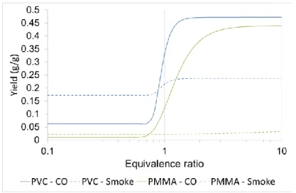
(30) Thèse de Sarah Chatenet, Université de Lille, 2019. Chapter I: Bibliography to modify the reaction pathway. The general mechanistic pathway of flame quenching by hydrogen chloride is described as follows [46]. The equation (1) is the generation of reactive species X● (Cl● in the case of PVC). From X● is generated a halogenated hydrogen halide HX (HCl in the case of PVC) by the reaction on the polymer chain (2). Equation (3) and (4) describe the radicals inhibition by the halogenated hydrogen halide and equation (5) describes the regeneration of the reactive species X●. (1) (2) (3) (4) (5). 3. Polymer combustion at macro-scale The polymer combustion at a molecular-scale has been described in the previous section. Nevertheless, the knowledge of the molecular-scale phenomena is not sufficient to assess the outcome of a fire. Indeed, during a fire, the phenomena between the condensed phase and the gas phase are highly coupled and gradients due to the thermal thickness of materials are determinant in the way that they react. In the same time, molecular-scale combustion characterization is of great interest as input data for macro-scale fire modeling.. 3.1.. Combustion efficiency convective and radiative components. In fires, combustion is rarely complete. Thus, the chemical heat release rate is less than the heat release rate for complete combustion. The ratio of the chemical heat release rate to the heat release rate for complete combustion is defined as combustion efficiency (Equation 2). Equation 2: Definition of combustion efficiency. 𝜒𝑐ℎ =. 𝑞̇ 𝑐ℎ 𝑚̇∆𝐻𝑐ℎ ∆𝐻𝑐ℎ = = 𝑞̇ 𝑇 𝑚̇∆𝐻𝑇 ∆𝐻𝑇. Where 𝜒𝑐ℎ is the combustion efficiency, 𝑞̇ 𝑇 and ∆𝐻𝑇 are the heat release rate for complete combustion (kW.m-2) and the heat of complete combustion (J.g-1) respectively, and 𝑞̇ 𝑐ℎ and ∆𝐻𝑐ℎ are the chemical heat release rate (kW.m-2) and the heat of combustion (J.g-1) respectively. 𝑚̇ is the fuel mass loss rate (g.s-1).. 30 © 2019 Tous droits réservés.. lilliad.univ-lille.fr.
(31) Thèse de Sarah Chatenet, Université de Lille, 2019. Chapter I: Bibliography The convective and radiative components of the combustion efficiency are defined in a similar fashion (Equation 3 and Equation 4 respectively). Equation 3: Definition of the convective component of the combustion efficiency. 𝜒𝑐𝑜𝑛𝑣 =. 𝑞̇ 𝑐𝑜𝑛𝑣 𝑚̇∆𝐻𝑐𝑜𝑛𝑣 ∆𝐻𝑐𝑜𝑛𝑣 = = 𝑞̇ 𝑇 𝑚̇∆𝐻𝑇 ∆𝐻𝑇. Where 𝜒𝑐𝑜𝑛𝑣 is the convective component of the combustion efficiency 𝜒𝑐ℎ . 𝑞̇ 𝑐𝑜𝑛𝑣 and ∆𝐻𝑐𝑜𝑛𝑣 are the convective heat release rate (kW.m-2) and the convective heat of combustion (J.g-1) respectively. Equation 4: Definition of the radiative component of the combustion efficiency. 𝜒𝑟𝑎𝑑 =. 𝑞̇ 𝑟𝑎𝑑 𝑚̇∆𝐻𝑟𝑎𝑑 ∆𝐻𝑟𝑎𝑑 = = 𝑞̇ 𝑇 𝑚̇∆𝐻𝑇 ∆𝐻𝑇. Where 𝜒𝑟𝑎𝑑 is the radiative component of the combustion efficiency 𝜒𝑐ℎ . 𝑞̇ 𝑟𝑎𝑑 and ∆𝐻𝑟𝑎𝑑 are the radiative heat release rate (kW.m-2) and the radiative heat of combustion (J.g-1) respectively. From Equation 2, Equation 3 and Equation 4, the definition of heat of combustion and combustion efficiency in terms of radiative and convective components can be deduced (Equation 5 and Equation 6). Equation 5: Heat of combustion in terms of convective and radiative heats of combustion components. ∆𝐻𝑐ℎ = ∆𝐻𝑐𝑜𝑛𝑣 + ∆𝐻𝑟𝑎𝑑 Equation 6: Combustion efficiency in terms of convective and radiative combustion efficiencies. 𝜒𝑐ℎ = 𝜒𝑐𝑜𝑛𝑣 + 𝜒𝑟𝑎𝑑 The chemical, convective and radiative heat release rates, heats of combustion of combustion efficiencies depend on the chemical structures of the materials and fire ventilation. The distribution of the chemical heat into convective and radiative components changes with fire size. The larger the fire size, the larger the fraction of the chemical heat distributed into the radiative component. The chemical, convective, and radiative heats of combustion and the heat release parameter values for well-ventilated fires of PMMA and PVC measured in the FPA (Fire Propagation Apparatus) are listed in Table 4. Table 4: Heat of combustion components for well-ventilated combustion of PMMA and PVC [47]. Material. ∆𝑯𝑻 (MJ.kg-1). ∆𝑯𝒄𝒉 (MJ.kg-1). ∆𝑯𝒄𝒐𝒏𝒗 (MJ.kg-1). ∆𝑯𝒓𝒂𝒅 (MJ.kg-1). PMMA. 25.2. 24.2. 16.6. 7.6. PVC. 16.4. 5.7. 3.1. 2.6 31. © 2019 Tous droits réservés.. lilliad.univ-lille.fr.
(32) Thèse de Sarah Chatenet, Université de Lille, 2019. Chapter I: Bibliography. 3.2.. Fire stages criteria. The stages of fire growth, in term of heat flux, temperature, oxygen content (to the fire and in the fire effluent), [CO2]/[CO] ratio, equivalence ratio φ and combustion efficiency 𝜒𝑐ℎ , have been classified in the standard ISO 19706 [48] (Table 5). Three main stages of fire are described from early to advanced stages. Non-flaming fires, corresponding to very early stages, i.e. before ignition or very advanced stages, i.e. after extinction, are firstly described. Then, well-ventilated flaming fires, covering early to mid-stages, are characterized. Finally, under-ventilated flaming fires, corresponding to mid to advanced stages, are detailed. While some real-life fires may be represented by a single fire stage, most will past through different stages. As they grow, all fires become oxygen depleted. It is of prior importance, in order to assess the fire toxicity at advanced stages to investigate fire behavior in lowventilated room fires, i.e. stage 3a, and in post flash-over fires, i.e. stage 3b. (Table 5).. 32 © 2019 Tous droits réservés.. lilliad.univ-lille.fr.
(33) Thèse de Sarah Chatenet, Université de Lille, 2019. Chapter I: Bibliography Table 5: ISO classification of fire stages, based on ISO 19706 [48]. Fire stage. Heat flux. Max temperature. Oxygen (vol.. Equivalence ratio. [CO]/[CO2]. Combustion. [kW.m-2]. [°C]. %). (φ). (vol. /vol.). efficiency. Fuel. Smoke. In. Out. (𝝌𝒄𝒉 ). Non-flaming 1a. Self-sustained smoldering. n.a.. 450 - 800. 25 - 85. 20. 0 - 20. /. 0.1 - 1. 50 - 90. 1b. Oxidative, external. /. 300 - 600. /. 20. 20. /. /. /. /. 100 - 500. /. 0. 0. /. /. /. 0 - 60. 350 - 650. 50 - 500. ≈ 20. 0 - 20. <1. < 0.05. > 95. 3a. Low ventilated room fire. 0 - 30. 300 - 600. 50 - 500. 15 - 20. 5 - 10. >1. 0.2 – 0.4. 70 - 80. 3b. Post flashover. 50 - 150. 350 - 650. > 600. < 15. <5. >1. 0.1 – 0.4. 70 - 90. radiation 1c. Anaerobic external radiation Well-ventilated flaming 2. Well-ventilated flaming Under-ventilated flaming. 33.
Figure
![Figure 4: Schematic diagram of the HACA reaction mechanism of PAH formation and growth [26]](https://thumb-eu.123doks.com/thumbv2/123doknet/3566114.104497/25.892.124.783.812.1061/figure-schematic-diagram-haca-reaction-mechanism-formation-growth.webp)
+7
Documents relatifs
