HAL Id: hal-01698410
https://hal.archives-ouvertes.fr/hal-01698410
Submitted on 13 Dec 2018
HAL is a multi-disciplinary open access
archive for the deposit and dissemination of
sci-entific research documents, whether they are
pub-lished or not. The documents may come from
teaching and research institutions in France or
abroad, or from public or private research centers.
L’archive ouverte pluridisciplinaire HAL, est
destinée au dépôt et à la diffusion de documents
scientifiques de niveau recherche, publiés ou non,
émanant des établissements d’enseignement et de
recherche français ou étrangers, des laboratoires
publics ou privés.
Life cycle assessment of a steam thermolysis process to
recover carbon fibers from carbon fiber-reinforced
polymer waste
Andréa Oliveira Nunes, Luciano Rodrigues Viana, Pierre-Marie Guineheuc,
Virgínia Aparecida da Silva Moris, Jane Maria Faulstich de Paiva, Radu
Barna, Yannick Soudais
To cite this version:
Andréa Oliveira Nunes, Luciano Rodrigues Viana, Pierre-Marie Guineheuc, Virgínia Aparecida da
Silva Moris, Jane Maria Faulstich de Paiva, et al.. Life cycle assessment of a steam thermolysis
process to recover carbon fibers from carbon fiber-reinforced polymer waste. International Journal
of Life Cycle Assessment, Springer Verlag, 2018, 23 (9), pp.1825-1838. �10.1007/s11367-017-1416-6�.
�hal-01698410�
Life cycle assessment of a steam thermolysis process to recover
carbon fibers from carbon fiber-reinforced polymer waste
Andréa Oliveira Nunes1,2 &Luciano Rodrigues Viana1&Pierre-Marie Guineheuc1&Virgínia Aparecida da Silva Moris2&Jane Maria Faulstich de Paiva2&Radu Barna1&
Yannick Soudais1
Abstract
Purpose Carbon fibers have been widely used in composite materials, such as carbon fiber-reinforced polymer (CFRP). Therefore, a considerable amount of CFRP waste has been generated. Different recycling technologies have been pro-posed to treat the CFRP waste and recover carbon fibers for reuse in other applications. This study aims to perform a life cycle assessment (LCA) to evaluate the environmental im-pacts of recycling carbon fibers from CFRP waste by steam thermolysis, which is a recycling process developed in France. Methods The LCA is performed by comparing a scenario where the CFRP waste is recycled by steam-thermolysis with other where the CFRP waste is directly disposed in landfill and incineration. The functional unit set for this study is 2 kg of composite. The inventory analysis is established for the different phases of the two scenarios considered in the study, such as the manufacturing phase, the recycling phase, and the end-of-life phase. The input and output flows associated with each elementary process are standardized to the functional unit. The life cycle impact assessment (LCIA) is performed using the SimaPro software and the Ecoinvent 3 database by the implementation of the CML-IA baseline LCIA method and the ILCD 2011 midpoint LCIA method.
Results and discussion Despite that the addition of recycling phase produces non-negligible environmental impacts, the im-pact assessment shows that, overall, the scenario with recycling is less impactful on the environment than the sce-nario without recycling. The recycling of CFRP waste reduces between 25 and 30% of the impacts and requires about 25% less energy. The two LCIA methods used, CML-IA baseline and ILCD 2011 midpoint, lead to similar results, allowing the verification of the robustness and reliability of the LCIA results.
Conclusions The recycling of composite materials with re-covery of carbon fibers brings evident advantages from an environmental point of view. Although this study presents some limitations, the LCA conducted allows the evaluation of potential environmental impacts of steam thermolysis recycling process in comparison with a scenario where the composites are directly sent to final disposal. The proposed approach can be scaled up to be used in other life cycle as-sessments, such as in industrial scales, and furthermore to compare the steam thermolysis to other recycling processes. Keywords Carbon fiber-reinforced polymer . Composite . Life cycle assessment . Recycling . Steam thermolysis . Thermal process . Waste valorization
1 Introduction
The use of carbon fibers has widely increased in a number of applications such as aerospace, wind energy, automotive, sporting goods, and other industrial fields, due to their excel-lent characteristics like high mechanical properties, low weight, high corrosion resistance, temperature tolerance, and low thermal expansion (Wang et al.2016; Ma et al. 2016; Industry Experts2013). Despite the high price of carbon fiber,
Responsible editor: Shabbir Gheewala
* Andréa Oliveira Nunes andreaoliveira_n@hotmail.com
1 RAPSODEE Research Center, University of Toulouse, Mines - Albi, Campus Jarlard, 81013 Albi, France
2 Department of Production Engineering, University of São Carlos, Campus Sorocaba, Rodovia João Leme dos Santos, Km 110, Sorocaba, São Paulo 18052-780, Brazil
the global demand is expected to grow from 46,000 t in 2011 to 140,000 t in 2020 (Roberts2011).
More than 97% of carbon fiber produced is processed into composite materials, such as carbon fiber-reinforced polymers (CFRPs) (Jahn2013). These composites have acquired great importance in major industrial sectors, mainly in the aerospace and automotive industry. For example, in the aircraft industry, the new Boeing 787 and Airbus A350 have up to 50% of their weight in CFRP. Consequently, an increasing amount of CFRP waste is also generated. The sources of waste include out-of-date pre-pregs, manufacturing cutoffs, testing mate-rials, production tools, and end-of-life (EoL) components (Pimenta and Pinho2011). As composite materials are very difficult to fractionate into elemental components, the waste has been mainly disposed in landfills or incinerated (Morin et al.2012). However, these techniques have became strictly regulated by the environmental legislations. In Europe, waste directives have limited landfill disposal and imposed that 95% of average weight of end-of-life vehicles manufactured after January 2015 must be recycled (EU 2000/53/EC).
The economic and environmental factors have motivated the development of recycling technologies, including mechan-ical recycling (shredding, crushing, milling), chemmechan-ical process (solvent, catalyst, or supercritical fluids), and thermal process (pyrolysis, oxidation, steam thermolysis) (Morin et al.2012; Oliveux et al.2015; Sun et al.2015). The aim is to recover the carbon fibers, as close as possible to their initial state, in order to envisage a reuse in other applications.
Mechanical recycling involves comminution techniques to reduce the size of the composite waste into granulated frac-tions (Pickering2006). This process does not recover individ-ual fibers, and the mechanical properties of the recycled fibers are significantly affected. On the other hand, the chemical process (solvolysis) provides very high retention of fiber length and mechanical properties, as well as a high potential for material recovery from polymer matrix (resin) (Pimenta and Pinho2011; Morin et al.2012). However, hazardous sol-vents for the environment are generally used, and under su-percritical conditions, high pressures are required (Liu et al. 2004, Pinero-Hernanz et al.2008).
The thermal recycling by pyrolysis is already used indus-trially. Pyrolysis consists of a thermal degradation of the resin in the absence of oxygen, at atmospheric pressure and temper-atures between 450 and 750 °C. The matrix (resin) degrada-tion produces an oil, gas, and a carbonaceous residue (char). The char formation on the carbon fiber surface is a situation that should be avoided, since the fibers must be free of resi-dues to be reused in the formulation of new composites. Thus, the pyrolysis is generally combined with a post-oxidizing treatment in the presence of air (oxygen) to obtain clean fibers (without residual char). Nonetheless, high temperature and highly oxidizing atmosphere lead to a higher degradation of the carbon fibers (Yang et al.2012; Oliveux et al.2015).
The steam thermolysis process has been developed in the RAPSODEE Laboratory, Albi, France. This process uses su-perheated steam, as an oxidant medium, under pyrolysis con-ditions to decompose the polymer matrix of the composite and reclaim the carbon fibers. The matrix degradation produces oil and gases, as well as in the pyrolysis process. The presence of steam as a soft oxidant produces a less oxidizing atmosphere than the thermal processes in the presence of air, leading to greater degradation of the resin and the removal of residual char on the fiber surface without an extensive reduction of mechanical properties of the remaining carbon fibers. The carbon fibers recovered from the optimized steam thermolysis process present a resin-free and uniform surface and retain over 80% of their original tensile strength (Ye et al.2013; Nunes2015).
Another reason for the increase in research and develop-ment of recycling technologies is the price of carbon fiber, a high-value-added material (cost over US$30 per kg), which reflects the high energy consumption in their manufacturing (Baker and Rials2013). The recycling of carbon fibers from CFRP waste contributes to the sustainability and sustainable development of industrial processes, as well as leads to re-source and energy savings for their production (Yang et al. 2012). However, while the recycling processes allow such benefits, an assessment of their environmental performance is still needed. Recycling is considered environmentally ap-propriate when the environmental impacts of the process are smaller than the impacts generated by alternative disposal practices (landfills, incineration) and virgin material produc-tion (Witik et al.2013).
Life cycle assessment (LCA) is an environmental manage-ment tool used to assess the environmanage-mental impacts associated with a product, process, or service throughout its entire life cycle, from raw material extraction to the final disposal (SETAC1993; Georgakellos2002). Several studies have been developed in order to evaluate the environmental impacts from recycling of different types of waste, like e-waste, plas-tics, wood waste, and composites (Menikpura et al. 2014; Arena et al.2003; Kim and Song2014; Witik et al.2013).
In the case of composite waste, specifically the recycling of CFRP, some studies employing LCA methodology were per-formed. For the mechanical recycling of carbon fiber compos-ite, Howarth et al. (2014) propose a model to estimate the energy demand in mechanical recycling by a milling process and therefore provide new data set for a further LCA. Li et al. (2016) conducted a life cycle cost (LCC) and a LCA research in order to evaluate financial and environmental performance of mechanical recycling of carbon fiber-reinforced polymers, comparing with landfill and incineration in a UK context. In that work, the treatment by mechanical recycling produced the lowest global warming impact compared with the other disposal methods. However, mechanical recycling presented high costs and low rate of carbon fiber recovering. Pinçaud
et al. (2014) evaluated the environmental impacts of the chem-ical recycling of carbon fiber/epoxy composite by solvolysis under supercritical water. In that case, the recycling process provides an average reduction of approximately 80% for all impact categories compared to disposal via landfill. Witik et al. (2013) carried out a study to compare the environmental viability of recycling by pyrolysis against incineration and landfill disposal, including an assessment of how reused ma-terials may change the environmental impacts. The data of the pyrolysis recycling process were based on commercially tech-nical specifications and literature.
In the present work, a LCA was performed to assess the environmental impacts of the recycling of carbon fiber from CFRP waste by steam thermolysis process, identifying the sources of impacts of this process conducted in France. This recycling process was compared with the French classic dis-posal scenario, 50% landfill and 50% incineration, in order to position the steam thermolysis process from an environmental point of view against a classic disposal scenario.
2 Methodology
The methodology of LCA is structured by ISO series 14040 standards and consists of four steps: goal and scope definition, inventory analysis, impact assessment, and interpretation (ISO 2006).
2.1 Goal and scope definition
The goal of this study is to compare the steam thermolysis recycling process with the French classic disposal scenario by using two life cycles of a CFRP composite in two different scenarios: one of them without recycling with an end of life of 50% disposing in landfill and 50% in incineration and the other one with recycling carbon fibers by steam thermolysis process.
2.1.1 Functional unit
The functional unit set for this study is 2 kg of composite (1 kg of long fiber composite and 1 kg of short fiber composite) to compare the scenario with the steam thermolysis recycling process with the other scenario without recycling. To attend the objective of this LCA (comparison of two different waste management scenarios), a mass-based functional unit is cho-sen rather than selecting a specific composite product. For this reason, in the two scenarios, it is assumed that the composites have the same application.
It is estimated that the two facilities associated with the recycling process (the steam thermolysis reactor and the cut-ting machine used to cut the composite waste) has a lifespan of 10 years. It is also considered that the steam thermolysis
reactor has a treatment capacity of about 3000 kg of compos-ites over 10 years.
2.1.2 System boundaries
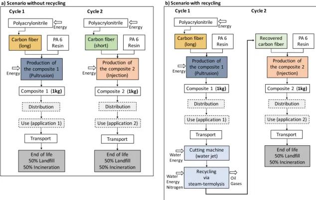
Figure1shows the life cycle stages and the system boundaries of CFRP composite for the two scenarios covered in this study. The scenario without recycling is composed of two life cycles in parallel, one in long fiber composite and the other in short fiber composite. Thus, it can be compared with that of recycling. In fact, in the steam thermolysis recycling process, the recovered carbon fibers are necessarily reduced in length. Their use in a new composite formulation requires the imple-mentation of an adapted process to the size of these short fibers (Fig.1). It is also imperative that both scenarios follow the same functional unit, i.e., 2 kg of composite (1 kg of long fiber composite and 1 kg of short fiber composite).
In the scenario without recycling, both identified parallel cycles take place in the same way (Fig.1a: cycle 1 and cycle 2). The new carbon fibers (long and short) are combined with the resin polyamide 6 (PA6) to produce 1 kg of composite in each cycle, i.e., 2 kg in total. The only difference between these two parallel cycles is the composite manufacturing pro-cess, which is appropriate to each type of starting fiber. The pultrusion manufacturing process is used to produce long fiber composites, and the injection manufacturing process is well adapted for the production of short fiber composites (Fig.1). Then, once the composite material is produced, it goes on to the distribution and use phase, and after that, it is sent to end of life (50% landfill and 50% incineration).
In the case with recycling by steam thermolysis (Fig.1b), after the first use phase, the composite waste (1 kg) is transported to the treatment site, where it is cut using a water jet machine, in order to fit in the steam thermolysis reactor. At the end of recycling process, short carbon fibers are recovered to reproduce again 1 kg of composite material. Finally, after the second use phase, the short fiber composite is disposed in landfill and incineration. It is assumed that the recycling of the carbon fibers takes place only once.
It is also considered that the two composites have, respec-tively, the same use in both scenarios: 1 kg long fiber com-posite (use 1) and 1 kg short fiber comcom-posite (use 2), as shown in Fig.1.
This methodology of comparing two parallel cycles in the scenario without recycling with the other of the recycling pro-cess enables avoiding the allocation issue of the recycling stage.
As mentioned above, the steam thermolysis process has been developed in France. Thus, this LCA study aims to eval-uate waste treatment within the geographical boundaries of France.
2.2 Inventory analysis
The life cycle inventory (LCI) is the collection and calculation data of material, energy, and emission flows of a product sys-tem (ISO1998). The inventory input and output flow analysis is established on the elementary processes for the different phases of the two systems considered in the study. In this work, it can be identified the manufacturing phase, the distri-bution and use phase, the recycling phase, and the end-of-life phase. In our case, the distribution and use phase is not includ-ed in the inventory analysis. In fact, as previously mentioninclud-ed, it is assumed that the two composites have, respectively, the same use, and therefore, the impacts of this phase are the same in both scenarios.
The life cycle assessment was performed considering as product a thermoplastic composite of carbon fiber and poly-amide 6 resin (carbon fiber/PA6). All inventory data related to the steam thermolysis process were experimentally deter-mined by tests conducted at the pilot scale.
The optimized steam thermolysis process leads to a degra-dation rate of the resin higher than 99%. The recovered carbon fibers present a resin-free uniform surface and retain over 80% of their original tensile strength. The mechanical tensile prop-erties of the composite made with recycled fibers from the steam thermolysis (breaking strength 136 MPa, elastic modu-lus 8.4 GPa) are close to those of the composite made with virgin fibers (breaking strength 141 MPa, elastic modulus 8.9 GPa) (Boulanghien et al.2015; Nunes2015). In addition, the microstructure of both recovered carbon fibers and virgin
ones was subject to analysis in environmental scanning elec-tron microscopy (ESEM). Elemental analysis (CHNS) was also conducted to determine the exact composition of carbon fibers. The ESEN images show that carbon fiber surface re-covered by steam thermolysis appeared to be resin-free and virtually undamaged (Fig.2). The elemental analysis indicates that the composition of the recycled carbon fibers (N 3.23%, C 93.19%, H 0.09%, S 0.01%) is also close to the virgin carbon fibers (N 2.57%, C 95.69%, H 0%, S 0%). As the consequence of an oxidation under superheated steam condition, a minor reduction in the carbon weight fraction of the recycled carbon fibers is observed (Ye et al.2011,2013; Nunes2015).
The carbon fibers recovered by steam thermolysis have a reduced length (50 mm), limited primarily by the reactor size. However, many applications require the use of short cut fibers, i.e., finite length fibers. The stiffness of staple fiber compos-ites is lower than that of the unidirectional composcompos-ites. Nevertheless, the staple fiber composites can be shaped more easily, mainly using injection molding process, especially where rapid production of complex geometry parts is required, such as in the automobile sector for primary structures and internal parts of vehicle (Ogi and Inoue2006; Boulanghien 2014).
2.2.1 Manufacturing phase
The manufacturing phase takes into account the different manufacturing processes of raw materials (polyacrylonitrile,
Carbon fiber (long) ResinPA 6 Production of the composite 1 (Pultrusion) Composite 1 (1kg) Distribution Use (application 1) End of life 50% Landfill 50% Incineration Carbon fiber (short) ResinPA 6 Production of the composite 2 (Injection) Distribution End of life 50% Landfill 50% Incineration
a) Scenario without recycling
Cycle 1 Cycle 2 Transport Transport Polyacrylonitrile Polyacrylonitrile Energy Energy Energy Energy Composite 2 (1kg) Use (application 2) Carbon fiber (long) ResinPA 6 Production of the composite 1 (Pultrusion) Distribution Cutting machine (water jet) Cycle 1 Transport Polyacrylonitrile Energy Energy Water Energy Nitrogen Recycling via steam-termolysis Water Energy Oil Gases Recovered
carbon fiber ResinPA 6 Production of the composite 2 (Injection) Distribution Transport End of life 50% Landfill 50% Incineration Cycle 2 b) Scenario with recycling
Composite 1 (1kg) Composite 2 (1kg)
Use (application 2) Use (application 1)
resins), intermediate products (carbon fiber), and end products (composites).
It is worth to remind that the functional unit is 2 kg of composite divided in 1 kg of long fiber composite and 1 kg of short fiber composite. The chosen composite consists of 55% by weight of carbon fiber and 45% by weight of resin (PA6). It is assumed that the carbon fibers and composites are manufactured on the industry partner site located in Pau, France. The fibers of polyacrylonitrile (PAN) are used as raw material for the manufacture of carbon fibers. According to Griffing and Overcash (2010), 1.82 kg of PAN is required to produce 1 kg of carbon fiber. As reported in literature by Song et al. (2009) and by the industrial partner, the energy employed in the production of carbon fibers is about 286 MJ kg−1.
Once the manufacture of the carbon fiber is completed, the resin is added to shape the composite. The PA6 resin is furnished by an industry located in Indiana, USA. It is there-fore also necessary to consider the transport (ship and lorry) to the site of Pau, France, where the composite is manufactured. Two different composite manufacturing processes are used depending on the size of the fibers. As previously mentioned, the pultrusion is appropriated for long fiber (> 50 mm) com-posites, and the injection process is well known to be more suited for short and mid-long fiber composites (Boulanghien 2014). Table1shows the inventory of fiber production, com-posite manufacturing, and the assumptions related to the trans-port stage of this phase.
2.2.2 Recycling phase
The recycling phase is divided into two parts: cutting of com-posites and the steam thermolysis process. The cutting is nec-essary to reduce the size of composite waste in order to facil-itate the feeding process and the efficacy of the steam thermolysis treatment. In this study, this task is performed by a water jet cutting machine, the Byjet Pro 3015.
The Byjet Pro 3015 is a robust machine (9850 kg), used mainly for machining materials in large scale. However, this work is based on a pilot scale, where the steam thermolysis reactor has a treatment capacity of only 1 kg per day. Therefore, it is assumed that only part of the machine working
time is dedicated to cutting the composite wastes under inves-tigation in this study.
It was assumed that the machine, which has a dimension of 300 × 150 × 23 cm and a maximum cutting capacity of 50 m min−1, operates 300 days per year and 8 h per day, i.e., a total working time of 24,000 h for the whole lifespan. It should be remembered that the cutting machine and the steam thermolysis reactor have a lifespan of 10 years, and it is en-visaged to treat 3000 kg of composite waste by steam thermolysis over 10 years. The use percentage of the machine is calculated based on the desired size of composite parts (5 × 5 × 0.028 cm). Thus, a cutting rate of 20 m min−1was estimated and considered to be suitable for cutting 1 kg of c o m p o s i t e w a s t e , i . e . , a b o u t 6 6 6 . 6 7 c m3
(ρcomposite= 1.5 g cm−3). The machine working time dedicated
only to cutting the composite wastes is calculated about 231 h. Therefore, the use percentage of the cutting machine is about 0.96%.
The raw materials needed for the construction of the cutting machine (steel, aluminum, copper), as well as the water and energy used to cut the composites, are amortized over a period of 10 years, also considering the percentage of use. The in-ventory of this step is shown in Table2. In collaboration with the industrial partner, the transport distance between the com-posite waste disposal site and the recycling facility, where the cutting machine and the steam thermolysis reactor are placed, is estimated at about 600 km. It is planned to collect the com-posite waste in a collection center in the city of Marseille and to transport them to the recycling site located in Brevans, France.
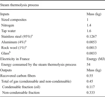
Thereafter, the steam thermolysis process takes place. The sized composite wastes are introduced into the reactor under an inert atmosphere (nitrogen) and in the presence of steam, where they are kept at the ideal temperature needed to achieve the resin degradation. The amounts of nitrogen and water are determined on the optimal conditions established by pilot-scale tests. During the steam thermolysis, the following out-puts are produced: a solid phase, which consists of the recov-ered carbon fibers, and a gas phase, consisting of a condens-able fraction (oil) and a non-condenscondens-able fraction. The amount of each output flow is calculated based on the material balance performed for the process from experiments conducted in the
Fig. 2 ESEN images of virgin carbon fibers (left) and recovered carbon fibers by steam
steam thermolysis pilot reactor. Table3shows the inventory of steam thermolysis process. The materials used for the con-struction of the steam thermolysis reactor, such as steel, alu-minum, and rock wool, are also considered in this inventory. According to the characterization of the gases by gas chro-matography, the non-condensable gases, produced by the res-in degradation, consist primarily of hydrocarbons, carbon di-oxide (CO2), and carbon monoxide (CO). It is considered that
these gases then pass through a combustion gas boiler and are released into the atmosphere as carbon dioxide. The energy released by the combustion of these gases can be used to produce heat energy (Gustafsson 2013; Honus et al. 2016). The amount of CO2produced from the combustion reaction
and the heat of reaction generated for each gas are shown in Table 4. The treatment of 1 kg of composite by steam thermolysis generates about 0.76 kWh of energy (Table4). In addition, for the condensable fraction, the oil obtained can
be used as fuel (Devaraj et al.2015; Krutof and Hawboldt 2016). Therefore, in this LCA, this oil is considered as avoided impacts.
2.2.3 End-of-life phase
It should be recalled that the scenario without recycling con-sists of two parallel cycles: one in long fiber composite (1 kg) and another (1 kg) in short fiber composite. The composite wastes (2 kg) are directly sent to end of life after used, as shown in Fig.1a. On the other hand, in the recycling scenario, the first step of end of life is avoided by the introduction of the recycling stage. Finally, only the composite made with the recovered carbon fibers are sent to end of life, that means, 1 kg (Fig.1b).
As mentioned above, the geographical boundaries of this LCA study were defined within France, since the steam
Table 2 Inventory of cutting of
composite waste Cutting machine
Inputs Mass (kg) Waste composite 1 Stainless steel (85%)a 0.0267 Aluminum (10%)a 0.0031 Copper (5%)a 0.0016 Tap watera 0.3972
Electricity in France Energy (MJ) Energy consumed by the water jet cutting machinea 17.64
Output Mass (kg)
Sized composites 1
Transport kg km
Transport of composite waste to the recycling plant by truck 600 Weight of the cutting machine 9850 kg. Percentage of use 0.958%
aEstimated by the percentage of use Table 1 Inventory of
manufacturing phase Fiber manufacturing
Input Quantity (kg) Energy (MJ) Output Quantity (kg)
PAN 1 157.3 Carbon fiber 0.55
Composite manufacturing
Input Quantity Energy (MJ) (Song et al.2009) Output Quantity Long carbon fibers
PA 6 resin 0.55 0.45 Pultrusion 3.1 Composite (long fiber) 1 kg Short carbon fibers
PA 6 resin 0.55 0.45 Injection 19 Composite (short fiber) 1 kg Transport PA6 resin
Steps Lorry (km) Ship (km)
Indiana to Port of Boston (USA) 1700 – Port of Boston to Port of Bordeaux (France) – 5000 Bordeaux to Pau (France) 300 –
thermolysis process has been developed in this country. According to ORDIMIP (The Regional Observatory of Industrial Waste of Midi-Pyrénées, France), until now, there are no specific regulations for waste composites in France and general waste regulations have been applied. Recycling of composite materials is not yet an industrial reality. Nevertheless, the recovery routes are known and have been researched and developed (ORDIMIP2017).
In addition, the overall composition of household waste has not changed fundamentally in 15 years. In 2007, the distribu-tion among the different materials is quite close to that of 1993. The main categories are putrescible waste (32.2%), paper/cardboard (21.5%), glass (12.7%), plastics (11.2%), tex-tiles (10.6%, including sanitary textex-tiles), metals (3%), and different composite materials or unclassified (8.9%) (ADEME2014).
Therefore, the end-of-life scenario assumed is representa-tive of the current average end-of-life household waste in France, which is about 50% landfill and 50% incineration (ADEME 2012). It is also assumed an average distance of 100 km to final disposal site (Witik et al.2013).
2.3 Impact assessment
The LCIA is carried out using the SimaPro software and the Ecoinvent 3 database with the implementation, in a first mo-ment, of the CML-IA baseline method. This LCIA method is a result of the work undertaken by different scientists in the Center of Environmental Science of Leiden University (Guinee2002). The CML-IA baseline LCIA method is a mid-point approach, linking all stages of life cycle inventory via 11 impact categories: depletion of abiotic resources (minerals— kg Sb eq and fossil fuels—MJ), global warming (kg CO2eq),
ozone layer depletion (kg CFC-11 eq), human toxicity (kg 1,4-DB eq), freshwater aquatic ecotoxicity (kg 1,4-DB eq), marine ecotoxicity (kg 1,4-DB eq), terrestrial ecotoxicity (kg 1,4-DB eq), photochemical oxidation (kg C2H4eq),
acidifica-tion (kg SO2eq), and eutrophication (kg PO4eq).
In order to verify the robustness of results obtained using the baseline CML-IA method, another life cycle impact as-sessment method, the ILCD 2011 midpoint, was used. The ILCD 2011 midpoint LCIA method, which proposes 16 mid-point impact categories, was developed by the European Commission (EC-JRC-IES 2011). After analyzing different impact assessment methods and from a first pre-selection of existing methods and criteria definition, the European Commission established a new list of recommended methods for each impact category (Pré2016). The impact categories of this method are climate change (kg CO2eq), ozone depletion
(kg CFC-11 eq), human toxicity cancer and non-cancer effects (CTUh), particulate matter (kg PM 2.5 eq), ionizing radiation HH (kBq U235 eq), ionizing radiation E (CTUe), photochem-ical ozone formation (kg NMVOC eq), acidification (molc H+ eq), terrestrial eutrophication (molc N eq), freshwater
Table 4 Inventory of the
non-condensable gas Gas Percent Mass (kg) Combustion reaction CO2(kg) ΔH (kJ/mol) Energy (kWh) H2 0.6 0.0019 H2+ 1/2O2➔H2O 0 285.9 0.08 CH4 0.1 0.0002 CH4+ 2O2➔CO2+ 2H2O 0.0005 890.4 0.003 CO 26.8 0.0894 CO + 1/2O2➔CO2 0.1404 283.0 0.25 CO2 63.3 0.2107 – 0.2107 – – C2H4 2.4 0.0079 C2H4+ 3O2➔2CO2+ 2H2O 0.0247 1411.0 0.11 C2H6 1.5 0.0049 C2H6+ 7/2O2➔2CO2+ 3H2O 0.0143 1560.0 0.07 C3H6 5.4 0.0181 C3H6+ 9/2O2➔3CO2+ 3H2O 0.0568 2058.0 0.25 Total 100 0.333 0.4474 0.76 aPercentage by weight Table 3 Inventory of steam thermolysis process
Steam thermolysis process
Inputs Mass (kg) Sized composites 1 Nitrogen 1.4 Tap water 1.6 Stainless steel (95%)a 0.1267 Aluminum (4%)a 0.0053 Rock wool (1%)a 0.0013 Glassb 0.0033
Electricity in France Energy (MJ) Energy consumed by the steam thermolysis process 54
Outputs Mass (kg)
Recovered carbon fibers 0.55 Total of gas (condensable and non-condensable) 0.45 Condensable fraction (oil) 0.117 Non-condensable fraction 0.333 aEstimated by the weight of the steam thermolysis reactor bGlass jacketed reactor used to condense the outgoing gas
eutrophication (kg P eq), marine eutrophication (kg N eq), freshwater ecotoxicity (CTUe), land use (kg C deficit), water resource depletion (m3water eq), and mineral, fossil, and
re-newable resource depletion (kg SB eq).
3 Results and discussion
3.1 Environmental impact assessment using CML-IA baseline LCIA method
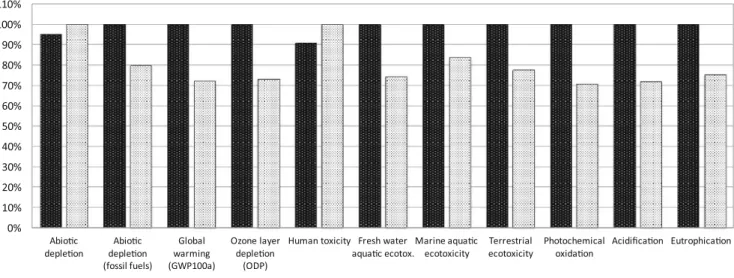
The life cycle assessment for 2 kg of composite is evaluated for both scenarios. Figure 3 shows the comparison between the scenario without recycling and with recycling, considering all life cycle phases, using the CML-IA baseline LCIA method.
The impact assessment shows that the scenario with recycling is less impactful on the environment in eight impact categories (Fig.3). In fact, for the other three categories (de-pletion of abiotic resources, human toxicity, and marine ecotoxicity), the difference of impacts between the scenarios with and without recycling is not significant enough to con-clude (less than 20%). In a LCA, the differences below 20% are not sufficient to conclude with certainty because it is al-ways necessary to consider the uncertainties of the input data and impact assessment methods. However, overall, the sce-nario with recycling is less harmful to the environment, de-creasing on average about 25% of impacts (Fig.3). It reduces the inputs and outputs of virgin carbon fiber manufacturing process.
In order to explore the impact sources for each scenario, a series of analyses are performed on the manufacturing and recycling life cycle phases. Figure 4 shows that during the manufacture of the new composite, it is the production of
carbon fibers that most contributes to all environmental im-pact categories, except to abiotic depletion. The imim-pacts of carbon fiber manufacturing are primarily related to energy consumption, followed by the impacts of the raw materials (Fig. 4). The carbon fiber manufacturing takes place twice for the scenario without recycling, which can explain the higher impacts in 8 out of 11 categories (Fig.3) compared to the scenario with recycling where carbon fiber manufacturing takes place just one time.
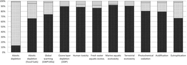
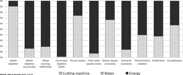
Considering now the scenario with recycling, as described previously, there is also the recycling phase (Fig.1b), which includes the transport of the composite waste to the recycling site, the cutting of these composites, and the steam thermolysis process with the outgoing gas and oil produced during the treatment. As it is observed in Fig.5, the cutting of composite and the steam thermolysis are the steps responsible for the majority of environmental impacts in all categories. These two elementary processes were then analyzed separate-ly (Figs. 6 and 7) to better understand the origin of these impacts.
According to Figs.6and7, the impact assessment shows that the energy required to the recycle phase is a major source of potential impacts on the environment. However, this energy represents only 45% of that used in the manufacturing of virgin carbon fibers, as shown in Fig.11by an energy balance for electricity throughout the life cycle phases for both scenar-ios under study. It also observed in Figs.6and7that for all categories, water has no significant potential impacts com-pared with the nitrogen and energy used. In the steam thermolysis process, the outgoing gas, which is converted into CO2by combustion, causes little impacts to global warming,
only about 10% of the total of kg CO2eq, as seen in Fig.7.
However, the cutting machine and the steam thermolysis reactor are an important source of impacts, mainly for the
0% 10% 20% 30% 40% 50% 60% 70% 80% 90% 100% 110% Abio!c
deple!on deple!onAbio!c (fossil fuels) Global warming (GWP100a) Ozone layer deple!on (ODP)
Human toxicity Fresh water
aqua!c ecotox.Marine aqua!cecotoxicity ecotoxicityTerrestrial Photochemicaloxida!on Acidifica!on Eutrophica!on
Method: CML-IA baseline V3.01 / EU 25 Scenario without recycling Scenario with recycling
categories abiotic depletion, human toxicity, marine ecotoxicity, and eutrophication (Figs.6and7). These impacts are due to the materials used in their construction (cooper, steel, aluminum, etc.). Copper and steel are the most impactful materials for the abiotic depletion, human toxicity, and eutro-phication, whereas aluminum is the main responsible for the impacts in marine ecotoxicity. In fact, these impacts occur during the production of these materials.
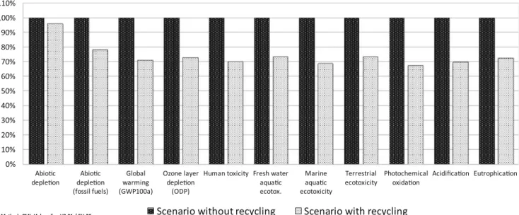
On the other hand, all data collected in the inventory for the virgin carbon fibers and composites do not consider any ma-terials for the construction of the machines used in their manufacturing process. Therefore, a new comparison between the scenarios with and without recycling was performed, as shown in Fig.8. This time, the materials for the construction of the cutting machine and the steam thermolysis reactor are not considered. Subtracting the materials used for the
construction of cutting machine and the steam thermolysis reactor (cooper, steel, aluminum), the environmental impacts of the recycling scenario decrease, mainly those related to human toxicity and marine ecotoxicity. Human toxicity cate-gory, for example, shows a significant reduction of 30%. The scenario with recycling is now less impactful to environment than the scenario without recycling, in 10 out of 11 categories (Fig.8). It is also observed in Fig.8that the reduction of the impacts increases, on average, from 25 to 30% when the ma-terials of construction are not taking into account in the LCA. Although the impacts related to the abiotic depletion have decreased, and now for the scenario with recycling is lower than in that without recycling, they are still very close in both scenarios (Fig.8). The difference is still not sufficient (less than 20%) to conclude for this impact category. In fact, looking at the stages of composite manufacturing, shown in
0% 10% 20% 30% 40% 50% 60% 70% 80% 90% 100% Abio!c
deple!on deple!onAbio!c (fossil fuels) Global warming (GWP100a) Ozone layer deple!on (ODP)
Human toxicity Fresh water
aqua!c ecotox.Marine aqua!cecotoxicity ecotoxicityTerrestrial Photochemicaloxida!on Acidifica!on Eutrophica!on
Method: CML-IA baseline V3.01 / EU 25
Virgin carbon fiber manufacturing
PA6 Resin
Composite manufacturing process
Fig. 4 Impacts associated with the composite manufacturing phase using virgin carbon fiber—CML-IA baseline
-10% 0% 10% 20% 30% 40% 50% 60% 70% 80% 90% 100% Abio!c
deple!on deple!onAbio!c (fossil fuels) Global warming (GWP100a) Ozone layer deple!on (ODP)
Human toxicity Fresh water
aqua!c ecotox.Marine aqua!cecotoxicity ecotoxicityTerrestrial Photochemicaloxida!on Acidifica!on Eutrophica!on
Method: CML-IA baseline V3.01 / EU 25
Transport to recycling site
Cu"ng of composites
Steam-thremolysis
Oil
Gas
Fig. 4, it is observed that the production of PA6 resin also generates significant impacts to abiotic depletion. It should be noted that the scenarios with and without recycling use the same amounts of PA6 resin to produce 2 kg of composite each, as presented in the system boundaries in Fig. 1. This explains the fact that abiotic depletion impacts are almost sim-ilar in the two cases studied and remain practically unchanged, with or without the construction materials, as shown in Figs.3 and8.
3.2 Environmental impact assessment using ILCD 2011 midpoint LCIA method
In order to verify the reliability of the impact assessment re-sults with the CML-IA baseline LCIA method, the ILCD 2011
midpoint LCIA method was also used to make a comparison between these two methods. The impact assessment results with the ILCD 2011 midpoint method for the comparison between the scenario without and with recycling are shown in Figs.9and10.
The ILCD 2011 midpoint LCIA method presents more impact categories than the CML-IA baseline. For example, human toxicity is divided into two subcategories (cancer ef-fects and non-cancer efef-fects) and eutrophication is divided into three subcategories (terrestrial, freshwater, and marine).
However, the results obtained with this method are equiv-alent and very close to those found with the CML-IA baseline LCIA method (see Figs.3and9). The results for some impact categories (climate change, ozone depletion, acidification, freshwater ecotoxicity, photochemical ozone formation) are
0% 10% 20% 30% 40% 50% 60% 70% 80% 90% 100% Abio!c
deple!on deple!onAbio!c (fossil fuels) Global warming (GWP100a) Ozone layer deple!on (ODP)
Human toxicity Fresh water
aqua!c ecotox.Marine aqua!cecotoxicity ecotoxicityTerrestrial Photochemicaloxida!on Acidifica!on Eutrophica!on
Method: CML-IA baseline V3.01 / EU 25
Cu"ng machine
Water
Energy
Fig. 6 Impacts associated with the cutting of composite waste—CML-IA baseline
-20% -10% 0% 10% 20% 30% 40% 50% 60% 70% 80% 90% 100% Abio!c
deple!on deple!onAbio!c (fossil fuels) Global warming (GWP100a) Ozone layer deple!on (ODP)
Human toxicity Fresh water aqua!c ecotox. Marine aqua!c ecotoxicity Terrestrial
ecotoxicity Photochemicaloxida!on Acidifica!on Eutrophica!on
Method: CML-IA baseline V3.01 / EU 25
Steam-thermolysis reactor
Nitrogen
Water
Energy
Oil
Gas
similar with the two LCIA methods. The results with the ILCD 2011 midpoint LCIA method show that the scenario with recycling causes less environmental impacts than the scenario without recycling in 12 out of 16 impact categories (Fig.9).
Regarding the other four categories, only for the human toxicity cancer effect category, the scenario without recycling has less impacts (Fig.9); for the other three categories (human toxicity non-cancer effects, freshwater eutrophication, and mineral, fossil, and renewable resource depletion), the
differences between the two scenarios are not significant enough to conclude (less than 20%), as shown in Fig.9.
Nevertheless, similar to the precedent LCIA method, the ILCD 2011 midpoint shows that, overall, the scenario with recycling is less impactful to the environment, also decreasing on average about 25% of impacts (Figs.3and9).
Moreover, as previously demonstrated with the CML-IA baseline LCIA method, the materials used for the construction of the cutting machine and the steam thermolysis reactor, present in the scenario with recycling, are an important source
0% 10% 20% 30% 40% 50% 60% 70% 80% 90% 100% 110% Abio!c
deple!on deple!onAbio!c (fossil fuels) Global warming (GWP100a) Ozone layer deple!on (ODP)
Human toxicity Fresh water aqua!c ecotox. Marine aqua!c ecotoxicity Terrestrial
ecotoxicity Photochemicaloxida!on Acidifica!on Eutrophica!on
Method: CML-IA baseline V3.01 / EU 25 Scenario without recycling Scenario with recycling
Fig. 8 Comparison between both scenarios without the materials of construction for the cutting machine and the steam thermolysis reactor—CML-IA baseline 0% 10% 20% 30% 40% 50% 60% 70% 80% 90% 100% 110%
ILCD 2011 midpoint V1.03
Scenario without recycling
Scenario with recycling
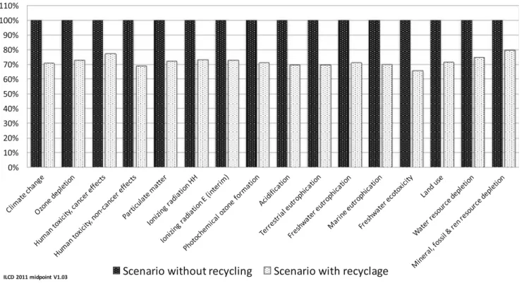
of impacts, mainly for the categories human toxicity, marine ecotoxicity, eutrophication, and abiotic depletion. Thus, in a similar way as was done with the precedent LCIA method, if these materials are not considered in the study perimeter, the impact assessment with the ILCD 2011 midpoint method shows that the environmental impacts of the recycling scenar-io also decrease, mainly those related to human toxicity (can-cer and non-can(can-cer effects), freshwater eutrophication, and mineral, fossil, and renewable resource depletion (Fig. 10). Therefore, the scenario with recycling becomes less impactful to environment than the scenario without recycling, in all 16
categories (Fig.10). The reduction of the impacts increases, on average, from 25 to 30% when the materials of construc-tion are excluded (Figs.9and10). This same increase of the reduction of impacts was also observed when the CML-IA baseline LCIA method was used (Figs.3and8).
The two LCIA methods used, CML-IA baseline and ILCD 2011 midpoint, lead to similar results even though these two LCIA methods have different characterization factors. The application of these two different LCIA methods made possi-ble to test the robustness of the results and to verify their reliability, validating the LCA study conducted.
0% 10% 20% 30% 40% 50% 60% 70% 80% 90% 100% 110%
ILCD 2011 midpoint V1.03
Scenario without recycling
Scenario with recyclage
Fig. 10 Comparison between both scenarios without the materials of construction for the cutting machine and the steam thermolysis reactor—ILCD 2011 midpoint -10 0 10 20 30 40 50 60 70 80 90 100 Carbon fiber
Manufacturing ManufacturingComposite Cu!ng Steam-thermolysis Recovered Energy Total
kW
h
Scenario without recycling
Scenario with recycling
3.3 Energy balance for electricity
In addition to the environmental impact assessment, an energy balance for electricity was conducted for both scenarios con-sidering every stage of the life cycle (Fig. 11). In the manufacturing stage, the scenario with recycling consumes less energy because it avoids the production of new carbon fibers. However, the steam thermolysis process and the cutting of the composites require a new demand of electricity. Despite this additional demand, the scenario with recycling consumes globally less energy. Overall, the total energy consumption can be reduced by 25%. The scenario with recycling also produces heat by the combustion of gaseous effluents from the steam thermolysis process (0.76 kWh per kg of composite).
4 Conclusions
The LCA presented in this study enabled a comparison of the environmental impacts in the life cycle of carbon fiber-reinforced plastic composite, considering two different scenar-ios: a scenario without recycling and another with recycling of carbon fibers by steam thermolysis.
The recycling of composite materials with recovery of car-bon fibers brings evident advantages from an environmental viewpoint. The scenario without recycling generates between 25 and 30% more impact and requires about 25% more energy than that with recycling. The recovery of carbon fibers saves raw materials and energy consumption in their manufacturing process. In addition, the recycling reduces the impacts associ-ated with the terrestrial and freshwater ecotoxicity, the fossil fuel depletion, as well as the contribution to global warming and ozone layer depletion.
However, the additional recycling phase causes non-negligible environmental effects. On the one hand, this phase requires a certain amount of energy for cutting composites and steam thermolysis process. This energy is the main source of impacts compared to other process inputs, such as water and nitrogen. On the other hand, the materials used for the con-struction of the cutting machine and the steam thermolysis reactor cause significant impacts. Nonetheless, the potential impacts of the scenario with recycling by steam thermolysis are globally lower than those of the scenario without recycling, where the composites are sent to landfill and incineration.
The application of two different LCIA methods (CML-IA baseline and ILCD 2011 midpoint) allows the verification of the robustness and reliability of the LCIA results. The two LCIA methods lead to similar results, validating the LCA study conducted.
The majority of inventory data collected is from experi-mental tests in pilot scale and technical data provided by the
industrial partners. However, some data should be used with caution, because they are based on assumptions that may vary. The cutting machine inputs and the transport stages consid-ered have been estimated based in technical data and some hypothesis. In fact, the inaccuracies of these data come from the fact that the study is currently still at the pilot scale.
Despite these limitations, this life cycle assessment study allows the evaluation of potential environmental impacts of steam thermolysis recycling process, comparing it with a sce-nario where the composites are directly sent to final disposal, incineration, and landfill. The proposed approach can be used in further life cycle assessments on a larger and industrial scale, and furthermore to compare the steam thermolysis to other recycling processes, such as pyrolysis, solvolysis, and/or mechanical recycling.
Funding information The authors of this paper would like to thank the French Agency for Environment and Energy Management (ADEME) and Alpha Recyclage Composites for their financial support.
References
ADEME - Agence de l’Environnement et de la Maîtrise de l’Energie (2012) Déchets – Edition 2012 – Chifres Clés. ADEME, France ADEME - Agence de l’Environnement et de la Maîtrise de l’Energie
(2014) Caractérisation des Déchets. ADEME, Francehttp://www. ademe.fr/expertises/dechets/chiffres-cles-observation/dossier/ caracterisation-dechets/resultats. Accessed 03 August 2017 Arena U, Mastellone ML, Perugini F (2003) Life cycle assessment of a
plastic packaging recycling system. Int J LCA 8(2):92–98 Baker DA, Rials TG (2013) Recent advances in low-cost carbon fiber
manufacture from lignin. J Appl Polym Sci 130:713–728 Boulanghien M (2014) Formulations de composites thermoplastiques à
partir de fibres de carbone recyclées par vapo-thermolyse, Dissertation, University of Toulouse - France
Boulanghien M, Da Silva S, Berthet F, Bernhart G, Soudais Y (2015) Using steam thermolysis to recycle carbon fibres from composite waste. JEC Compos Mag 100:69–70
Devaraj J, Robinson Y, Ganapathi P (2015) Experimental investigation of performance, emission and combustion characteristics of waste plas-tic pyrolysis oil blended with diethyl ether used as fuel for diesel engine. Energy 85:304–309
European Commission - Joint Research Centre (2011) International Reference Life Cycle Data System (ILCD) Handbook - recommen-dations for life cycle impact assessment in the European context, 1st edn. EUR 24571 EN. Publications Office of the European Union, Luxemburg
Georgakellos DA (2002) LCA as a tool for environmental management: a life cycle inventory case study from the greek market. Glob Nest Int J 4:93–106
Griffing E, Overcash M (2010) Carbon fibre HS from PAN. Chemical Life Cycle Database. http://www.environmentalclarity.com. Accessed 11 Aug 2015
Guinee J (2002) Handbook on life cycle assessment operational guide to the ISO standards. Int J LCA 7:311–313
Gustafsson M (2013) Pyrolysis for heat production—biochar the primary byproduct. Master’s Thesis in Energy Systems, University of Gävle Honus S, Kumagai S, Nemcek O, Yoshioka T (2016) Replacing conven-tional fuels in USA, Europe, and UK with plastic pyrolysis gases— part I: experiments and graphical interchangeability methods. Energy Convers Manag 126:1118–1127
Howarth J, Mareddy SSR, Mativenga PT (2014) Energy intensity and environmental analysis of mechanical recycling of carbon fibre composite. J Clean Prod 81:46–50
Industry Experts (2013) Carbon fibers and carbon fiber reinforced plastics (CFRP)—a global market overview. Industry Experts, India ISO - International Organization for Standardization (1998) ISO 14041:
environmental management—life cycle assessment—goal and scope definition and inventory analysis. ISO, Geneva
ISO - International Organization for Standardization (2006) ISO 14040: environmental management—life cycle assessment—principles and framework. ISO, Geneva
Jahn B (2013) Composites Market Report 2013. Carbon Composites e. V. (CCeV), Germany
Kim MH, Song HB (2014) Analysis of the global warming potential for wood waste recycling systems. J Clean Prod 69:199–207 Krutof A, Hawboldt K (2016) Blends of pyrolysis oil, petroleum, and
other bio-based fuels: a review. Renew Sust Energ Rev 59:406–419 Li X, Bai R, McKechnie J (2016) Environmental and financial perfor-mance of mechanical recycling of carbon fibre reinforced polymers and comparison with conventional disposal routes. J Clean Prod 127:451–460
Liu Y, Meng L, Huang Y, Du J (2004) Recycling of carbon/epoxy com-posites. J Appl Polym Sci 94:1912–1916
Ma Q, Gu Y, Li M, Wang S, Zhang Z (2016) Effects of surface methods treating methods of high-strength carbon fibers on interfacial prop-erties of epoxy resin matrix composite. Appl Surf Sci 379:199–205 Menikpura SNM, Santo A, Hotta Y (2014) Assessing the climate co-benefits from waste electrical and electronic equipment (WEEE) recycling in Japan. J Clean Prod 74:1–8
Morin C, Loppinet-Serani A, Cansell F, Aymonier C (2012) Near and supercritical solvolysis of carbon fibre reinforced polymers (CFRPs) for recycling carbon fibers as a valuable resource: state of the art. J Supercrit Fluids 66:232–240
Nunes AO (2015) Carbon fiber reinforced composites: recovery of car-bon fiber by steam-thermolysis, optimization of the process. Dissertation, University of Toulouse - France
Ogi K, Inoue H (2006) Temperature dependence of electrical resistance in carbon fiber and carbon fiber composites. Proceedings of the Twelfth U.S. – Japan Conference on Composite Materials 200–206 Oliveux G, Dandy LO, Leeke GA (2015) Current status of recycling of fibre reinforced polymers: review of technologies, reuse and resulting properties. Prog Mater Sci 72:61–99
ORDIMIP – L’orbservatoire de déchets en Midi Pyrénées. Les fiches déchets. ORDIMIP, Francehttp://www.ordimip.com/dechets?id= 100. Accessed 03 Aug 2017
Pickering SJ (2006) Recycling technologies for thermoset composite ma-terials—current status. Compos A Appl Sci Manuf 37:1206–1215 Pimenta S, Pinho ST (2011) Recycling carbon fibre reinforced polymers
for structural applications: technology review and market outlook. Waste Manag 31:378–392
Pinçaud M, Aymonier C, Loppinet-Serani A, Perry N, Sonnemann G (2014) Environmental feasibility of the recycling of carbon fibers from CFRPs by solvolysis using supercritical water. ACS Sustain Chem Eng 2:1498–1502
Pinero-Hernanz R, Dodds C, Hyde J, Garcia-Serna J, Poliakoff M, Lester E, Cocero MJ, Kingman S, Pickering S, Wong KH (2008) Chemical recycling of carbon fibre composites in nearcritical and supercritical water. Compos A Appl Sci Manuf 39:454–461
PRé (2016) PRé Consultants. SimaPro Database Manual – Methods Library. Pre –sustainability
Roberts T (2011) The Carbon Fibre Industry Worldwide 2011–2020: an evaluation of current markets and future supply and demand. Mater Tech Pub. ISBN 1 871677 64 5
Society of Environmental Toxicology and Chemistry (SETAC) (1993) Guidelines for life-cycle assessment: a ‘code of practice’. SETAC, Brussels
Song SY, Youn RJ, Gutowski GT (2009) Life cycle energy analysis of fiber-reinforced composites. Compos A Appl Sci Manuf 40:1257– 1265
Sun H, Guo G, Menon SA, Xu W, Zhang Q, Zhu J, Xing F (2015) Recycling of carbon fibers from fiber reinforced polymer using electrochemical method. Compos A Appl Sci Manuf 72:61–99 Wang L, Huang R, Zhou B, Zhang Y, Dong Y (2016) Carbon fibers
modified with silicone peroxide containing vinyl groups for silicone rubber reinforcement. Mater Lett 176:38–41
Witik RA, Teuscher R, Michaud V, Ludwig C, Manson JAE (2013) Carbon fibre reinforced composite waste: an environmental assess-ment of recycling, energy recovery and landfilling. Compos A Appl Sci Manuf 49:89–99
Yang Y, Boom R, Irion B, Heerden D-J, Kuiper P, Wit H (2012) Recycling of composites materials. Chem Eng Process Process Intensif 51:53–68
Ye SY, Bounaceur A, Soudais Y, Barna R (2011) Characterisation of carbon fibres reclaimed from steam-thermal treatment. ICCE -19 Annual International Conference on Composites and Nano Engineering. Shanghai, China
Ye SY, Bounaceur A, Soudais Y, Barna R (2013) Parameter optimization of the steam thermolysis: a process to recover carbon fibers from polymer-matrix composites. Waste Biomass Valoriz 4:73–86