HAL Id: hal-01716274
https://hal.archives-ouvertes.fr/hal-01716274
Submitted on 1 Mar 2019
HAL is a multi-disciplinary open access
archive for the deposit and dissemination of
sci-entific research documents, whether they are
pub-lished or not. The documents may come from
teaching and research institutions in France or
abroad, or from public or private research centers.
L’archive ouverte pluridisciplinaire HAL, est
destinée au dépôt et à la diffusion de documents
scientifiques de niveau recherche, publiés ou non,
émanant des établissements d’enseignement et de
recherche français ou étrangers, des laboratoires
publics ou privés.
Simulations of an Infrared Composite Curing Process
Sawsane Nakouzi, Johann Pancrace, Fabrice Schmidt, Yannick Le Maoult,
Florentin Berthet
To cite this version:
Sawsane Nakouzi, Johann Pancrace, Fabrice Schmidt, Yannick Le Maoult, Florentin Berthet.
Simula-tions of an Infrared Composite Curing Process. Advanced Engineering Materials, Wiley-VCH Verlag,
2011, Materials Process Engineering: Nantes 2010, 13 (7), pp.604-608. �10.1002/adem.201000344�.
�hal-01716274�
Simulations of an Infrared Composite Curing Process**
By Sawsane Nakouzi*, Johann Pancrace, Fabrice Schmidt, Yannick Le Maoult and Florentin Berthet
Epoxy resins have several applications in the aerospace and automobile industry. Because of their good adhesive proper-ties, superior mechanical, chemical and thermal properproper-ties, and resistance to fatigue and microcracking, they produce high performance composites. Since it is necessary to optimize the manufacturing time and costs and to determine the performance of these composites, some researchers[1–4]have studied infrared (IR) heating for the polymerization process. Others[5,6]have used IR energy for the preheating process.
In the technology presented here, the composite is cured in an IR oven (see Figure 1) which includes halogen lamps. The liquid resin infusion (LRI) process is used to manufacture the composite, whereby liquid resin is infused through a fiber reinforcement previously laid up in a one-sided mold.
These epoxy resins release an exothermic heat flux during the curing process, which can possibly cause an excessive temperature in the thickness. Consequently, for the produc-tion of high performance composites, it is necessary to know the thermal behavior of the composite during curing. The most detailed models for the curing process of composites using IR heaters have been presented by Chernet al.[1–4]They measured the radiative properties of graphite/epoxy and
glass/epoxy systems and modeled the radiative heat transfer in the glass/epoxy system as a volumetric radiation transport. Therefore, IR interactions with the graphite/epoxy system were modeled as a surface radiation transport.
Cossonet al.[7]developed numerical algorithms, based on a ray-tracing method. In-lab software, called Rayheat, predicts the volumetric distribution of the radiation intensity in a semi transparent medium. This software also models IR interac-tions with highly absorptive mediums, where the radiation transport is a surface radiation. In this paper, we present simulations of the IR curing process of a carbon/epoxy system. Numerical simulations were performed in order to determine the temperature distribution in the composite thickness during the polymerization process. The heat balance equation is coupled with the exothermic heat and the radiative heat flux using the commercial software Comsol
Multi-physicsTM. In order to introduce these simulations to an
industrial composite part, we validate the simulations of a simple sheet of composite.
Liquid Resin Infusion (LRI)
LRI is used for the impregnation process of fibers with resin. In this process, presented schematically in Figure 2, liquid resin with low viscosity is infused through fiber reinforcement, which is placed in a single-sided mold sealed with a vacuum bag. Before being impregnated by resin, the fiber reinforcement must be preheated by the IR lamps, in order to maintain the low viscosity of the resin and to facilitate its path through the reinforcement. This process combines the advantage of infusion at ambient pressure, short cycle time and low cost equipment with the ability to produce parts of [*]S. Nakouzi, J. Pancrace, Prof. F. Schmidt, Prof. Y. Le Maoult,
Dr. F. Berthet
Universite´ de Toulouse; Mines Albi, ICA (Institut Cle´ment Ader); Campus Jarlard, F-81013 Albi cedex 09, (France) E-mail: [email protected]
[**] Grateful acknowledgement to TOSHIBA LIGHTING for their
financial support.
Using IR energy is an efficient method of curing composites. In this paper, we study IR interactions
with the composite, which is placed in an IR oven. The liquid resin infusion technique is used for the
impregnation process of fibers with resin. Numerical simulations of the curing process for a carbon
fiber-reinforced epoxy (RTM6) system are presented. In-lab software called Rayheat based on ray
tracing algorithms and developed in Matlab is used to compute the radiative heat flux that impacts the
composite. A three-dimensional numerical model is developed in the finite element software Comsol
Multiphysics, where the heat-balance equation is coupled with the cure kinetic model of the resin. The
computed radiative heat flux is exported to Comsol Multiphysics and imposed as a boundary condition
on the top surface of the composite. This numerical model allows calculation of the temperature
distribution in the composite during curing, which is a key parameter that affects its mechanical
properties. We can predict also the evolution of the degree of cure as function of time.
complex shape. After the reinforcement has been impreg-nated, IR heaters are turned on in order to start the curing process of the composite.
Materials
The physical geometry of the composite is assumed to be a
sheet of dimension 160! 140 ! 6 mm3
. It is composed of a sequence of carbons plies embedded in an epoxy matrix. The carbon fiber lay-up shows plies rotated by 458 (nomenclature:
[0/0/þ 45/90/#45/0] s). Commercial epoxy resin RTM6
provided by the Hexel Corporation was used in our study. This resin was chosen because it is currently used in the aerospace and automobile industries.
Short wave halogen lamps (in the range 0.6–6 mm and
wavelength lmax¼ 1.2 mm at the lamp’s maximum relative
intensity) made by Toshiba Lighting Company were employed for the curing process. The lamps have variable power levels and a nominal power of 1 000 W. A tungsten filament is the IR emitter; it is surrounded by quartz glass and a kind of halogen gas-filled lamp.
IR Interaction
IR radiation processing of the polymeric materials is fast, volumetric (in semi-transparent media), direct and
control-lable. Several researchers have studied[8–11] the radiative
heating processes of polymers and semi transparent
med-iums. Cosson et al.[7] developed software called Rayheat in
order to predict the distribution of the radiative intensity in
PET preforms. Chern et al. [1–4] successfully studied the
radiative curing process of hoop-wound cylinders of gra-phite/epoxy and glass/epoxy. Previously, we have studied the curing process of a composite, the physical geometry of which corresponds to a carbon/epoxy block, manufactured by the LRI process. The recovery surface is semitransparent to IR radiation: 92% of the IR radiation is transmitted to the composite (this value was measured in an earlier work in the laboratory). Carbon fibers embedded in the epoxy resin
are very strong IR absorbers over broad spectral ranges at all wavelengths, while the composite has strong absorption
bands in some portions of the spectrum.[1]The mean value of
the spectral reflectance of the carbon/epoxy system is 15%, as taken from the literature.[2]
Ray Tracing
In ray tracing, we model radiation as rays of light. The propagation of the rays is only based on the laws of geometrical optics. The general idea is to simulate the interactions between the ray of light emitted by a source (in our case halogen lamps) and every object present in the scene (here, the IR oven), including multiple lamps, reflectors and the composite. In the ray tracing software, coiled tungsten is the IR emitter. It is
assumed to be a Lambertian grey body[7]and is modeled as a
cylinder with equivalent diameter. That is, we define a number N of rays emitted from the lamp; this number is chosen in a way to have a good agreement between the calculations costs and the needed precision of the results (see Figure 3). Then we start from a random point P on the IR emitter and trace the ray
emitted in a random direction. This directiond is defined by
two parameters Q2½0; p=2& and ’2½0; 2p&. These parameters are defined by stochastic variables:[12]
Q ¼ arcsin ffiffiffiffiffiffiX1
p
(1)
’¼ 2pX2 (2)
whereX1andX2are independent uniform stochastic variables in the range [0,1].
Each ray emitted by the source is defined by its origin, direction, and spectral intensity. Then the ray is tested against all objects in the scene to determine what it hits and if it intersects the composite (Figure 3). The different interactions between the ray and the objects present in the scene change the ray properties. In our ray tracing software, assumptions found in the literature are made for the different optical properties of
lamps, reflectors,[10] recovery surface and the carbon/epoxy
system.[1,2] They are referenced in Table 1 below. The ray
tracing method has been validated in a previous work in the laboratory[7]with an analytical solution given by view factor.[13]
Fig. 1. IR oven. This figure presents the IR oven used in our experiments. The composite is placed at the center of the oven, facing the IR heaters. A liquid resin infusion process is used to impregnate the carbon fiber reinforcement.
Fig. 2. Schematic presentation of the liquid resin infusion process. Reinforcement is placed in a one-sided mold. A vacuum pump assures the infusion of the resin through the reinforcement.
Fig. 3. Schematic presentation of the ray-tracing method. In this method we compute the origin and direction of each ray emitted by the IR heater and we study its intersection with the composite. Ray tracing method is used in our numerical simulations in order to compute the IR heat flux that impacts the top surface of the composite.
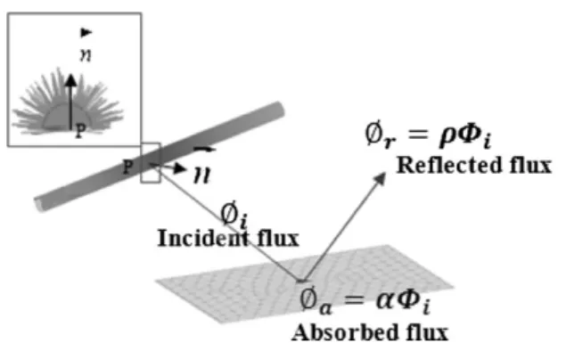
IR Oven and Boundary Conditions
Composite is exposed to radiation in the IR oven (see Figure 4). This one is composed of nine halogen lamps provided by Toshiba Lighting Company. The IR radiation is absorbed by the carbon ply present on the top surface of the composite. In addition this surface is a convective boundary surrounded by the air present in the oven, at temperature Tair(t). The frame of the composite is so thin in comparison with the surface, the edge effect becomes negligibly small; that is, we can ignore the heat exchanges all arround its contour. The bottom of the composite is in contact with a surface that is supposed to be a thermal insulation, but there is no real adiabatic surface. Bottom temperature was introduced as a boundary conditions in the finite element software Comsol. During curing, incident radiation is absorbed by the top surface of the carbon/epoxy composite. Then the composite is thermally heated in the thickness via conduction from its top surface. Figure 5 presents the IR density distribution as well as the boundary conditions.
Natural Heat Convection Coefficient
The natural heat transfer coefficient is obtained from a correlation for the horizontal plate with the heated surface
facing upward:[14] h¼kairNu
L (3)
Where Nu is the Nusselt number, kair is the air thermal
conductivity, andL is the characteristic length of the plate.
WithNu¼ cðGr:PrÞnwherePr is the Prandtl number, c¼ 0.13
andn¼ 1/3. The physical properties of atmospheric air in the previous equations are evaluated at a mean temperature, defined as:Tm¼ Ts#0:25ðTs#T1Þ, where Tsis the composite top surface temperature. The Garshof number is defined as GrL) ðgbðTS#T1ÞL3Þ=v2 where b is the thermal expansion
coefficient, and is evaluated atðTsþ T1Þ=2.
Kinetic Modeling
Kamal and Sourour[15] have shown that the following
model describes the cure kinetics of an epoxy resin: da
dt ¼ ðk1þ k2a
mÞð1#aÞn (4)
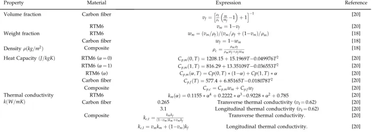
Table 1. Summary of the thermophysical properties used in the numerical simulations.
Property Material Expression Reference Volume fraction Carbon fiber v
f¼ rf rr m mf#1 " # þ 1 h i#1 [20] RTM6 vm¼ 1#vf [20] Weight fraction RTM6 wm¼ ðvm=rfÞ=ðvm=rfþ ð1#vmÞ=rmÞ [18] Carbon fiber wf¼ 1#wm [18] Density rðkg=m2Þ Composite rc¼ rmrf rmwfþrfwm [18]
Heat CapacityðJ=kgKÞ RTM6 (a¼ 0) Cp;mð0; TÞ ¼ 1208:15 þ 15:1969T#0:049976T2 [20]
RTM6 (a¼ 1) Cp;mð1; TÞ ¼ 816:29 þ 13:35109T#0:036553T2 [20]
RTM6 (a) Cp;mða; TÞ ¼ Cpð0; TÞ * ð1#aÞ þ Cpð1; TÞ * a [20]
Carbon fiber Cp;fðTÞ ¼ 577:4 þ 6:85165T#0:018078T2 [20]
Composite Cp;c¼ Cp;mwmþ Cp;fwf [20]
Thermal conductivity kðW=mKÞ
RTM6 kmðaÞ ¼ 0:1155 * a4þ 0:2222 * a3#0:9228 * a2þ 0:785 [20]
Carbon fiber 0.265 Transverse thermal conductivity (vf¼ 0.62) [20]
3.1 Longitudinal thermal conductivity (vf¼ 0.62) [20]
Composite k
c;t¼ð1#vmkÞkmmkfþvmkf
Transverse thermal conductivity. [20] kc;l¼ vmkmþ ð1#vmÞkf Longitudinal thermal conductivity. [20]
Fig. 4. Schematic presentation of the IR oven. The IR oven is composed of nine halogen lamps. This oven geometry configuration is used in our simulations in order to predict the heat flux on the top surface of the composite.
Fig. 5. Boundary conditions. IR heat flux that impact the top surface of the composite is taken as a boundary condition in the finite element software Comsol Multiphysics. The contour of the composite is so thin in comparison with its thickness that we can ignore heat exchanges all around its contour. The bottom surface of the composite is taken as a boundary condition.
ki¼ Aiexp # Ei
RT
$ %
i¼ 1; 2; 3 (5)
where ki are the rate constants with an
Arrhenius type of dependence with tem-perature andm and n are catalytic constants. Although the model of Kamal and Sourour contains several essential features, it ignores the influence of the glass transition
temperature Tg on the diffusion of the
macromolecules. This model has been extended in order to reflect the effect of vitrification, which induces a decrease of the resin reaction rate since mobility of macromolecules becomes very limited. This model was also used by other authors:[16,17] da dt ¼ k1kd k1þ kdþ k2kd k2þ kd am $ % ð1#aÞn (6) kd¼ k3exp #b f $ % (7) f¼ f0þ dðT#TgÞ (8)
where kdis a diffusion factor,k3the diffusion rate constant
with an Arrhenius type of dependence,b a constant of order
one, Tg the glass transition temperature, f a free volume
fraction of the polymer, f0 a free volume fraction for a
temperature equal to Tg, and d the thermal expansion
coefficient. For an amorphous polymer, which is the case of our composite,f0¼ 0.025 and d ¼ 4.8 ! 10#4K#1.
The glass transition temperature is modeled using the DiBenedetto equation:[17,18]
Tg¼ Tg0þ ððTg1#Tg0ÞlaÞ=ð1#ð1#lÞaÞ (9)
WhereTg0andTg1are the glass transition temperature of
unreacted and fully reacted resin, respectively, and l is the
material constant. These values were deduced from the literature.[19]
The kinetic parameters of resins can be calculated using linear regression algorithms by fitting model equations with differential scanning calorimetry (DSC) experimental data. In this paper, the kinetic parameters of the RTM6 resin were taken from published estimates.[19]
Energy Equation
The composite transient temperature can be evaluated by the heat balance equation assuming an instantaneous equilibrium temperature between the resin and the fibers at each time:[18]
rcCp;c@T
@t ¼ rkcrT þ ymrmHu @a
@t (10)
WhereHuis the ultimate heat of reaction of the resin, and a the degree of curing. The material property parameters required in this analysis are listed in Table 1. The thermal
conductivity of the composite kcðW=mKÞ was measured by
Lecointe for carbon-reinforced RTM6 resin.[20]
Experimental
Experimental measurements were carried out in order to validate numerical simulations of the IR curing process of carbon/epoxy composite. Temperature acquisition in the thickness of the composite is achieved using three thermo-couples of type K, having an 80 mm diameter. These thermocouples were fixed in the fiber reinforcement through the thickness. Then, air was aspirated with the vacuum bag and the fibers were compacted. A schematic presentation of the thermocouple positions is presented in Figure 6.
Validation
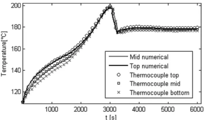
Experiments show a good agreement with the numerical results. In the experimental process, carbon fibers placed in the mold were preheated by the IR lamps present in the oven. Then the IR heaters were turned off and the RTM6 resin at
808C infused through the reinforcement using the LRI
process. In order to refer to the same operating conditions between experiments and simulations (we did not address in our simulations the filling step, during which resin flows through the fiber reinforcement), IR heaters were turned on after infusion took place and stabilization of the resin in the mold. The curing process was achieved with 22% of the nominal power of the IR heaters. Because the degradation temperature of the matrix is 2208C, we turned off the lamps at
2008C. The lamps were then turned on again when the
temperature decreased to 1758C (see Figure 7). We introduced
the experimental operating conditions as input data in our simulations: oven and composite geometry, air temperature,
Fig. 6. Experimental set-up. Temperature acquisition is assured by three thermocouples type K, placed in the thickness of the composite and having an 80 mm diameter.
Fig. 7. Curing temperature validation: thermocouple temperature acquisitions through the thickness of the composite and numerical results. This figure shows the good agreement between the experimental data and the numerical results.
initial temperature of the composite, bottom temperature of the composite.
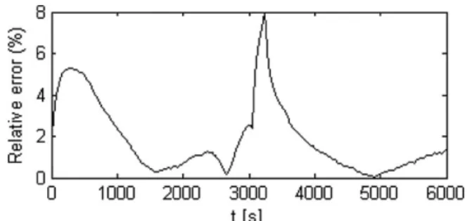
The relative error between thermocouple’s actual and numerically predicted temperature is calculated using Equation 11 and presented in Figure 8:
E¼
ffiffiffiffiffiffiffiffiffiffiffiffiffiffiffiffiffiffiffiffiffiffiffiffiffiffiffiffiffiffiffiffiffiffiffiffiffiffiffi P2
i¼1ðTexp#TnumÞ2
P2 i¼1Texp2 v u u t ! 100 (11) Conclusions
A novel process for curing composites is the use of IR heaters. The composite is placed in an IR oven, facing the IR heaters. Numerical simulations were carried out in order to predict the thermal behavior of the composite during the curing process. Radiative heat flux is computed in Matlab, using an algorithm developed in-lab. This heat flux is exported to the finite element software Comsol Multiphysics, where it is taken as a boundary condition on the top surface of the composite. The exothermic heat flux released by the epoxy matrix during the curing process is coupled with the heat equation. Then, we can predict temperature distribution in the composite during the polymerization and the degree of cure. We validate our numerical results with experimental measurements. So far we have discussed IR curing of carbon fiber-reinforcement epoxy matrix. Curing glass/epoxy sys-tems is our interest for future works, because of the volumetric distribution of the radiative intensity in the semi transparent mediums.
[1] B.-C. Chern, T. J. Moon, J. R. Howell,J. Compos. Mater.
2002, 36, 1905.
[2] B.-C. Chern, T. J. Moon, J. R. Howell,J. Compos. Mater.
2002, 36, 1935.
[3] B.-C. Chern, T. J. Moon, J. R. Howell, J. Heat Transfer
1995, 117, 685.
[4] B.-C. Chern, T. J. Moon, J. R. Howell, J. Heat Transfer
2003, 125, 137.
[5] S. Adanur, A. McClain, B. Xu,J. Elastomers Plast. 2003, 35, 257.
[6] J. E. Cunningham, P. F. Monaghan, M. T. Brogan,
Com-pos. Part A 1998, 51, 61.
[7] B. Cosson, F. Schmidt, Y. Le Maoult, M. Bordival,Int. J. Mater. Forming 2010. DOI: 10.1007/s12289-010-0985-8.
[8] M. Bordival, Y. Le Maoult, F. Schmidt,Polym. Eng. Sci.
2009, 49, 783.
[9] C. Champin, J. F. Agassant, M. Bellet, F. M. Schmidt,
Y. Le Maoult, 20th International Conference of Polymer
Processing Society June 20–24, Akron, Ohio, USA 2004. [10] F. M. Schmidt, Y. Le Maoult, S. Monteix,J. Mater. Process.
Technol 2003, 143, 225.
[11] S. Andrieu, Y. Le Maoult, F. M. Schmidt, 18th
Inter-national Conference of Polymer Processing Society, Gui-mare`s, Portugal 2002.
[12] M. Pharr, G. Humphreys, Physically Based Rendering:
from Theory to Implementation, Elsevier Science, USA 2004.
[13] H. Leuenberger, R. A. Person, ASME Annual Meeting,
New York 1956.
[14] M. N. Ozisik, in Heat Transfer – a Basic Approach,
McGraw-Hill International Editions 1985.
[15] M. E. Ryan, A. Dutta,Polymer 1979, 20, 203.
[16] T.-M.-H. Nguyen, in Syste`mes E´poxy-Amine Incluant un
Catalyseur Externe Phe´nolyque: Cine´tique de Re´ticulation-Vieillissement Hydrolytique. PhD Thesis, Acade´mie de Nice, Universite´ du Sud Toulon 2007.
[17] J. M. Balvers, H. E. N. Bersee, A. Beukers, K. M. B.
Jansen, Structures, Structural Dynamics, and Materials
Conference, Schaumburg 2008.
[18] E. Ruiz, F. Trochu,J. Compos. Mater, 2005, 39, 881. [19] P. I. Panagiotis, I. K. Partridge,J. Appl. Polym. Sci. 2000,
77, 1419.
[20] D. Lecointe, inCaracte´risation et Simulation des Processus de Transferts lors d’Injection de Re´sine pour le Processus RTM, PhD Thesis: Ecole Doctorale Sciences pour l’Inge´-nieur de Nantes 1999.
Fig. 8. The relative error between the thermocouple temperature and the numerical results.