• Aucun résultat trouvé

2017 — Applied electromagnetic environment cognition to improve a radio communication link

N/A
N/A
Protected

Academic year: 2021

Partager "2017 — Applied electromagnetic environment cognition to improve a radio communication link"

Copied!
172
0
0

Texte intégral

(1)

by

Juan AVILÉS CASTILLO

THESIS PRESENTED TO ÉCOLE DE TECHNOLOGIE SUPÉRIEURE

IN PARTIAL FULFILLMENT OF THE REQUIREMENTS

FOR THE DEGREE OF DOCTOR OF PHILOSOPHY

Ph. D.

MONTREAL, MARCH 28, 2017

ÉCOLE DE TECHNOLOGIE SUPÉRIEURE

UNIVERSITÉ DU QUÉBEC

(2)

This Creative Commons licence allows readers to dowload this work and share it with others as long as the

author is credited. The content of this work may not be modified in any way or used commercially.

(3)

BOARD OF EXAMINERS

THIS THESIS HAS BEEN EVALUATED

BY THE FOLLOWING BOARD OF EXAMINERS:

Mr. Ammar Kouki, Thesis Supervisor

Department of Electrical Engineering at École de technologie supérieure

Mr. Stephane Coulombe, Chair, Board of Examiners

Department of Software and IT Engineering at École de technologie supérieure

Mr. Francois Gagnon, Member of the jury

École de technologie supérieure

Mr. Tayeb A. Denidni, External Evaluator

Institut national de la recherche scientifique

THIS THESIS WAS PRESENTED AND DEFENDED

IN THE PRESENCE OF A BOARD OF EXAMINERS AND THE PUBLIC

ON FEBRUARY 27, 2017

(4)
(5)

ACKNOWLEDGMENT

First of all, my deepest gratitude to my wife and children for their love and great patience.

This endeavor would not have been possible without their support.

I wish to express my heartfelt thanks to my supervisor Professor Ammar Kouki for his

support, advices and encouragement. My deepest appreciation for his patience, availability

and positivism which have added a valuable experience to my professional life.

I am in debt to Professor Sixto Garcia from ESPOL whose encouragement and help made

possible my final decision to pursue doctoral studies.

I also would like to thank my colleagues of the LACIME Laboratory, especially the ‘Iranian

team’ Hassan, Hossein, Mustafa, Aref and Aria for his friendship. I will surely miss the little

technical discussions within or beyond our areas of study together with the anecdotes and

jokes. My appreciation to Norman Gravel for his great logistic support.

Thanks to my colleagues of ESPOL already graduated and still students at ETS who shared

their experiences and provided much help.

Finally I would like to acknowledge the decisive financial support from my University

Escuela Superior Politecnica del Litoral (ESPOL)

(6)
(7)

APPLICATION DE LA COGNITION DE L’ENVIRONNEMENT

ÉLECTROMAGNÉTIQUE POUR L’AMÉLIORATION D’UN LIEN DE

COMMUNICATION RADIO

Juan AVILÉS CASTILLO

RÉSUMÉ

Avec l'adoption continue de dispositifs mobiles, il est prévu que la capacité du réseau

cellulaire grandisse à des taux qui ne sont pas compatibles avec les réseaux micro-ondes

actuels.

Ainsi, l’intérêt donc dans les ondes à bandes millimétriques (30-300 GHz) a

augmenté considérablement puisqu’elles offrent la possibilité d’une assignation du spectre

plus large par rapport à celle existante actuellement au-dessous le 3 GHz. Spécifiquement,

en ce moment l’on considère que la bande de 28-38 GHz possède un grand potentiel pour

fournir des services de téléphonie mobile de cinquième génération. Dans ce sens, les

mesures in situ démontrent qu’il est possible d’établir des liaisons de communications

faisables

dans un rayon de 200 mètres, même en absence de visibilité directe, en utilisant des

antennes directionnelles. Ce scénario est différent de celui utilisé dans les systèmes actuels

de téléphonie portable dans lesquels l’application/utilisation des antennes directionnelles

normalement s’effectue après avoir complété l’accès au réseau et non pas par l’accès en

soi-même. Une estimation de canal en utilisant des méthodes de formation de faisceau hybride a

été proposée comme une solution, mais au détriment de l'application de plus d'une chaîne de

radiofréquence. D’autre part, les techniques d’estimation à détection compressée qui tirent

avantage des caractéristiques éparses des canaux à ondes millimétriques, qui fournissent une

représentation précise du profil angulaire de puissance

et qui requièrent un petit nombre de

mesures révèlent être sensibles au bruit additif. Cette réalité peut affecter principalement des

sites qui ne disposent pas d'une ligne de visibilité direct où le niveau du signal peut n’est pas

suffisamment élevé.

Dans cet écrit, nous profitons des caractéristiques de propagation spécifiques du site où le

système est déployé. Cette connaissance peut être exploitée dans la station de base sous la

forme d'une base de données relative à la position de l'utilisateur. L’information sur la

localisation d'un utilisateur devient de plus en plus accessible sur les appareils mobiles

comme un élément intégré et avec un degré de précision croissant.

Dans la première partie, il est démontré que la sélection préalable des orientations des

antennes les plus efficaces pour générer la valeur la plus élevée de puissance pour les

utilisateurs situés dans des positions sans visibilité directe, accélère le lien d'accès. Plus

précisément, pour la bande de 28 GHz, les données de simulation d’un outil du traçage de

rayons appliqué dans les milieux urbains spécifiques indiquent que l’application des valeurs

arbitraires des angles est sans bénéfice pour les utilisateurs. Certains angles peuvent être

totalement ou partiellement bloqués par des bâtiments proches qui limitent l’éclairage

en

radiofréquence à une puissance maximale d’une valeur inférieure par rapport à ce qui peut

être obtenu avec d'autres. Les simulations montrent qu’on peut obtenir un bénéfice de plus de

2 dB dans un certain nombre de mesures de puissance consécutives, mais cette amélioration

(8)

de la performance semble être affectée par la sévérité du type de propagation de corridor

urbain existant. En outre, étant donné que les angles discrets de la station de base ou de

l’équipement de l’utilisateur sont répétés individuellement ou collectivement dans des

nombreuses et différentes localisations géographiques, la répartition en pourcentage des

angles qui génèrent une puissance maximale peut également être exploitée pour fournir des

améliorations supplémentaires. On développe une méthode de traçage de rayons simplifiée

pour déterminer les meilleurs angles ainsi que leur répartition en pourcentage non uniforme.

L'impact de la réduction de l’ensemble des angles est déterminé en mesurant l'amélioration

du rapport signal/ bruit lorsque les angles de la station de base ainsi que l'équipement de

l’utilisateur varient aléatoirement un certain nombre de fois. En outre, une comparaison entre

le nombre de commutations de faisceaux d'antenne nécessaire pour établir la liaison d'accès

dans une procédure d'alignement de l'antenne spécifique est effectuée. Ces résultats peuvent

être utiles dans les systèmes utilisant la formation de faisceau analogique.

Dans la deuxième partie, nous avons développé un algorithme d'alignement d'antenne en

profitant de la connaissance des caractéristiques de propagation spécifiques sous la forme

d'une base de données liée à la localisation géographique de l'équipement utilisateur. On

considère les deux cas dans lesquels la station de base connaît la situation exacte et inexacte

de l’utilisateur. Nous profitons de l’observation selon laquelle l’angle de la station de base

associée au premier trajet de propagation est répété

à des points à l'intérieur d'un cercle de

rayon D autour de la position indiquée. Le procédé développé peut éclairer de manière

appropriée l'utilisateur, même dans le cas d'une information inexacte de la position. La

détermination du meilleur angle de BS facilite l'application d'un faisceau étroit d'antenne

dans la phase initiale du processus d'alignement, ce qui offre l'avantage d'un plus haut niveau

de puissance au démarrage et par conséquent, d’un nombre réduit d’alignement. Les résultats

de simulation montrent que l'algorithme proposé possède une performance similaire ou

meilleure par rapport à un processus hiérarchique conventionnel modifié, à condition que la

situation exacte de l’usager se trouve dans la zone circulaire du rayon D contenant des points

de la base de données. Par ailleurs, le rayon D peut avoir une valeur un peu supérieure à

l'erreur maximale du système de positionnement géographique, sans produire une plus

grande variation dans la performance. D'un autre côté, on a prouvé qu'il n'est pas nécessaire

d’appliquer une base de données de très haute résolution. Les résultats obtenus en appliquant

des erreurs maximales de position allant jusqu'à 10 m et de résolution de la base de données

allant jusqu'à 4 m, respectivement, indiquent aussi que la distance entre les points de la base

de données peut augmenter jusqu'à 2 m sans impact majeur sur les performances. Ces

résultats sont maintenus en variant le niveau maximal de puissance reçue à l'équipement

utilisateur.

Dans la troisième partie, on développe l'application de la connaissance des caractéristiques

spécifiques de la propagation d'un site pour augmenter la capacité de liaison. Étant donné que

la base de données peut avoir l'information de toutes les directions de propagation existantes

dans une position spécifique de l'utilisateur, nous élargissons l'algorithme développé dans la

section précédente en ajoutant une seconde trajectoire sous la condition que la capacité totale

soit supérieure à celle qui peut être obtenue avec seulement la première étape. L'inexactitude

de la position informée par l'utilisateur force le choix d’un point de référence de la base de

(9)

données pour le rapprochement des principaux angles de la seconde trajectoire. Les

simulations utilisant le traçage des rayons dans trois zones bien définies montrent que, sous

des règles de décision définies, l'augmentation de la capacité supplémentaire qui pourrait être

atteint avec l'application de l'algorithme est assez proche du cas idéal où l'utilisateur indique

la position exacte. Étant donné qu'une étape supplémentaire est nécessaire pour que la station

de base communique les angles de la deuxième trajectoire à l’équipement de l’utilisateur, le

procédé d’alignement d’antenne en utilisant une base de données, continue à être plus rapide

par rapport à la méthode d'alignement hiérarchique modifiée. En outre, on analyse l'effet de

la résolution de la base de données sur les performances de l’algorithme proposé dans des

conditions statistiques et variables.

Mots-clés: Base de données, traçage de rayons, antenne directionnelle, alignement de

l'antenne, station de base, équipement de l'utilisateur, radiofréquence, localisation de

l'utilisateur.

(10)
(11)

APPLIED ELECTROMAGNETIC ENVIRONMENT COGNITION TO IMPROVE

A RADIO COMMUNICATION LINK

Juan AVILÉS CASTILLO

ABSTRACT

With the continuous adoption of mobile devices, the cellular wireless capacity is projected to

grow at rates that would not be supported in current microwave networks, therefore, a high

interest in millimeter-wave bands (30-300 GHz) has risen since they provide the possibility

of a larger spectrum allocation compared to the one below 3 GHz. Specifically, the 28-38

GHz band is currently considered to have a high potential to provide fifth generation cellular

services. In this regard, field measurements show that viable links, even in non-line of sight

conditions, can be established within a radius of 200 meters but these need to be found with

the help of directional antennas. This scheme is different from the one used in current cellular

systems in which the application of directional antennas is normally applied after the network

access is completed and not for the access itself. Channel estimation implemented with

hybrid beamforming methods have been proposed as solutions but at the expense of more

than one radio frequency chain.

On the other hand, compressed sensing channel estimation

techniques which take advantage of the sparse characteristics of the millimeter-wave

channels giving an accurate representation of the power angle profile and a very much

reduced beamforming overhead turns to be sensitive to additive noise. This latter effect can

produce an impact mostly in non-line of sight locations where the signal power may not be

high enough.

In this work, we take advantage of the site-specific propagation characteristics in which the

system is deployed. This knowledge can be exploited at the base station side in the form of a

database linked to the position of the user equipment.

The location information is becoming

more accessible in cellular equipment as a built-in feature with an increasing degree of

accuracy.

In the first part, it is shown that a prior selection of the most effective base station antenna

directions to deliver the highest possible power value to users located in non-line of sight

positions can speed up an access link. Specifically for the 28 GHz band, simulation data

from a ray tracing tool applied in specific urban environments indicate that the utilization of

arbitrary base station angles in a cell search procedure is not of maximum benefit for the

users. Some of the angles are largely or partially blocked by nearby buildings restricting the

radio frequency illumination to a maximum power of a lower value compared to what can be

obtained from others. A power level benefit higher than 2 dB can be obtained in a defined

number of consecutive power measurements, however this performance improvement

appears to be conditioned by the severity of the existing street canyon propagation.

Moreover, given that the same base station or user equipment discrete angles are repeated

individually or together at many different geographical positions, their percentage

distribution for maximum power delivery can also be exploited for further improvement.

A

simplified ray tracing procedure is developed to identify the best base station angles together

(12)

with their non-uniform percentage distribution. The application impact (two scenarios) of this

reduced set of angles is determined by contrasting the improvement in the signal to noise

ratio when both the base station and user equipment change their main beam orientations in a

random fashion a certain number of trials. Additionally, a comparison of the number of

antenna beam switches needed for an access link in a particular antenna alignment procedure

is performed. These results may be helpful especially for those systems using analog

beamforming.

In the second part, we developed an antenna alignment algorithm exploiting specific

propagation knowledge in the form of a database linked to the geographical position of the

user equipment. Both cases in which the base station knows the exact and inexact location of

the user are considered. We take advantage of the observation that the base station angle

associated to the first propagation path serving the user repeat exactly or approximately in the

database points located within a circle of radius D around the reported position. This result

allows to illuminate appropriately the user even for the case of an inexact position

information. The determination of the best BS angle facilitates the application of a narrow

beamwidth antenna in the initial stage of the antenna alignment process providing the

advantage of an increased starting illumination power and consequently of a reduced total

number of alignment steps. Through ray tracing simulations it is shown that the proposed

algorithm has similar or better performance relative to a modified classical hierarchical

procedure as long as the exact geographical position is located inside a circular area of

database points. Moreover the radius D of the circular area can be set to a value

a little

larger

than the maximum error of the positioning system without much variation on the

performance. On the other hand, there is no need of a very high resolution database.

Simulation results applying maximum position errors up to 10 m and database resolutions up

to 4 m, respectively, indicate that the distance between the database points can be increased

up to 2m without much impact. These outcomes are sustained when the maximum power

level received at the user equipment varies.

In the third part, we expand the application of a site-specific propagation characteristics

knowledge to increase a link capacity. Given that a database can have information of all

propagation paths associated to a specific position of the user, we extend the algorithm

developed in the previous part to take advantage of a second path as long as the total capacity

link is larger than what can be obtained with just the first path. The inaccuracy in the position

reported forces the selection of a reference point in the database to approximate the main

angles of the second path. Ray tracing simulations in three well defined areas show that for

the decision rules adopted, the additional capacity gain accomplished with the algorithm is

fairly close to the ideal case where the exact user position is known. Given that only one

additional step is needed for the base station to communicate the angle information of the

second path to the user, a database dependent alignment process remains faster relative to a

comparable modified classical hierarchical method. Additionally, we examine the effect of

the database resolution on the performance of the proposed algorithm for static and variable

conditions.

(13)

Keywords: Database, Ray tracing, Directional antenna, Antenna alignment, Base station,

User equipment, Radio frequency, User position.

(14)
(15)

TABLE OF CONTENTS

Page

INTRODUCTION ...1

CHAPTER 1

BACKGROUND ...13

1.1

Propagation characteristics of mmW band (outdoor links) ...13

1.2

Compressive sensing in channel estimation in mmW ...14

1.3

Classical hierarchical alignment procedure ...15

1.4

Hybrid beamforming ...16

1.5

Ray Tracing ...17

1.5.1

Wireless Insite ... 17

1.6

Genetic algorithm ...18

1.7

Global Positioning System (GPS) and Assisted GPS (A-GPS) ...19

CHAPTER 2

EXPLOITING SITE-SPECIFIC PROPAGATION CHARAC-

TERISTICS IN DIRECTIONAL SEARCH AT 28 GHz ...21

2.1

Introduction ...21

2.2

System model and simulation methodology ...24

2.2.1

System model ... 24

2.2.2

Simulation methodology ... 32

2.3

Approximate identification of the angle range ...34

2.3.1

Angle identification assessment ... 39

2.4

Performance impact ...44

2.4.1

Maximum received SNR using the complete and best sets of BS

angles ... 45

2.4.2

Maximum received SNR using a limited number of BS angles ... 48

2.4.3

Maximum received SNR in a mobile user using a limited number

of BS angles ... 52

2.4.4

Number of switches in a beam training ... 53

2.5

Conclusions ...54

CHAPTER 3

POSITION-AIDED MILLIMETER WAVE BEAM TRAINING

UNDER NLOS CONDITION ...55

3.1

Introduction ...55

3.2

System model and simulation methodology ...58

3.2.1

System model ... 58

3.2.2

Simulation methodology ... 59

3.3

Proposed Hierarchical Method ...60

3.3.1

Number of steps ... 73

3.4

Algorithm performance ...74

3.4.1

Static case... 74

3.4.2

Random variation of the maximum received power ... 77

(16)

CHAPTER 4

TAKING ADVANTAGE OF A SECOND PROPAGATION PATH

AT 28 GHz UNDER NLOS CONDITIONS ...83

4.1

Introduction ...83

4.2

System model and simulation methodology ...85

4.2.1

System model ... 85

4.2.2

Simulation methodology ... 86

4.3

Proposed method ...86

4.4

Algorithm performance ...94

4.4.1

Static case... 94

4.4.2

Random variation of the maximum received power ... 98

4.5

Conclusions ...100

CONCLUSION ...101

APPENDIX I

DISTRIBUTION FUNCTION OF MAXIMUM POWER IN L

READINGS ...105

APPENDIX II

SPATIAL FILTERING ON PROPAGATION DATA ...113

APPENDIX III BS ANGLE IDENTIFICATION ...115

APPENDIX IV ORDERED (ASCENDING)

VALUES PER EACH UE IN

SERVICE AREAS ...119

APPENDIX V SNR COMPARISON ...121

APPENDIX VI DATABASE GENERATION ...125

APPENDIX VII MODIFIED CLASSICAL HIERARCHICAL PROCEDURE

SIMULATION ...129

APPENDIX VIII LINK WITH TWO PROPAGATION PATHS ...131

(17)

LIST OF TABLES

Page

Table 2.1

Percentage of combinations where

(ẑ) −

(ẑ) ≥ 0 ...30

Table 2.2

Linear routes and grid of points ...37

Table 2.3

Percentage of positions of the user where ∆

(ẑ) ≥ 0 in service

areas 1 and 2 ...48

Table 3.1

(

)

≥ ep and difference in prBestBSang for ep≤epmax ...69

Table 3.2

Comparison of the number of antenna alignment steps per 180

o

(UE)

angle span...73

Table 3.3

D value for the first maximum ‘tspd’ ...80

Table 4.1

Additional link capacity - second beam, different/same BS angle.

Different DBres and D (>epmax) ...97

(18)
(19)

LIST OF FIGURES

Page

Figure 0.1

Objectives and methodology stages ...8

Figure 2.1

Cellular System ...25

Figure 2.2

Illustration of 1-D maximum RF coverage for different BS angles ...25

Figure 2.3

UE antenna pattern and the multipath component arriving at

...26

Figure 2.4

UE antenna gain gu(θ

) versus the angle difference

=

...26

Figure 2.5

Cumulative Distribution of

and Ẑ = max[

… .

],

L=3, N=8 ...28

Figure 2.6

Study area...33

Figure 2.7

Simulation setups 1 and 2 ...36

Figure 2.8

Percentage of UEs per BS angle reaching maximum power

(setup 1,3) ...37

Figure 2.9

Percentage of UEs per BS angle reaching max. power (setup 2, 4) ...38

Figure 2.10

Percentage of UE positions per UE angle (max. rcvd. power)

in setups 1,2 ...39

Figure 2.11

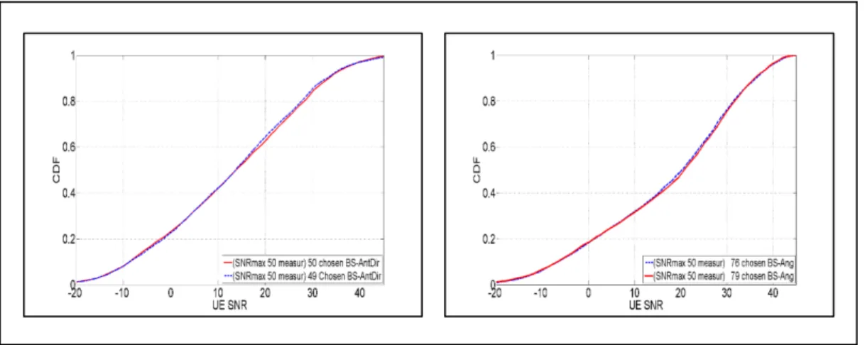
Specific Cumulative Distribution Functions FBS49, FBS76, FUEsc1, FUEsc2 ...39

Figure 2.12

Setup 3 and 4 (Tx1/Tx2 center left/bottom) ...40

Figure 2.13

Precision difference: 49 (setup 1) versus

50 (setup 3) and 76 (setup 2) versus 79 (setup 4) ...41

Figure 2.14

Percentage of UE positions per BS angle (max. SNR) in setup 3 ...42

Figure 2.15

Percentage of UE positions per BS angle (received power < thres) ...43

Figure 2.16

SNR at UE positions (500) ...44

Figure 2.17

UE MaxSNR in 50 (25) measurements. 121 versus 49 BS angles

(setup 3) ...46

(20)

Figure 2.18

UE maxSNR in 50 (25) measurements 121 versus 76 BS angles

(setup 4) ...47

Figure 2.19

Sum of power difference (dB) versus k-BS angle groups (setup 3) ...50

Figure 2.20

Number of blockings and power difference sum (dB) versus

k-BS angle groups ...51

Figure 2.21

SNR in setups 3 and 4. Twenty five BS

equally-spaced versus 25 selected angles (equal probability) ...51

Figure 2.22

SNR statistics for a UE mobile (30 Km/h) in setup 3 ...52

Figure 2.23

UE beam switches until power ≥ -85 dBm (thres) in setup 3 ...54

Figure 3.1

Simplified cellular system ...58

Figure 3.2

BS with a database. UE has a random initial angle ...59

Figure 3.3

BS applies directly a high antenna gain ...60

Figure 3.4

DB reference curve and UE power reads ...62

Figure 3.5

Algorithm 3.1 versus modified hierarchical. BS knows the exact UE

position ...63

Figure 3.6

SNR of the closest point for different DB resolutions ...65

Figure 3.7

Circular area of DB points (radius D) around the reported inexact

UE position ...66

Figure 3.8

Best BS & UE angles in â1 (1

st

row) and â2 (2

nd

row)

for DBres=0.5m. UEs are represented as black dots ...67

Figure 3.9

Angle pairs (first power lobe) of all DB points

and UE (exact e inexact positions) in å

DB

(â1). ...67

Figure 3.10

Probability of BS angle repetition versus D in å

DB

1)

for the conditions

′ ϵ [ep

, e

p

+ ∆e

p] and ep ≤ epmax. DBres = 0.5 m ...68

Figure 3.11

SNR obtained (â1) from the application of one or the best of two or

three BS angles inside å

DB

(selection based on repetition or power

differences) ...72

Figure 3.12

Performance of algorithm 3.2 (â1). DBres=0.5m,

D=e

pmax=10m (epmax=2m,6m,10m, green curves) ...74

(21)

Figure 3.13

Performance of algorithm 3.2 (â2). DBres=0.5m,

D= e

pmax =10m (epmax=2m,6m,10m, green curves) ...75

Figure 3.14

Performance of algorithm 3.2 (â1,

â

2).

D=e

pmax=10m, DBres= 1m, 2m, 3m, 4m. ...76

Figure 3.15

SNR comparison (â1). Power distribution variation at UE,

D=e

pmax=10m. dDBr ≤ D, DBres=1 and 4m ...77

Figure 3.16

SNR comparison (â2). Power distribution variation at UE,

D=e

pmax=10m, dDBr

≤ D, DB

res=1m,2m,3m,4m ...78

Figure 3.17

Relative sum of power difference versus D for â1,

â

2

. DB

res

=2m ...79

Figure 3.18

Relative sum of power difference versus D for â1,

â

2

. DB

res

=1.5m ...80

Figure 4.1

Cellular system ...85

Figure 4.2

Propagation power lobes at a specific location ...87

Figure 4.3

Database points used by the proposed algorithm ...89

Figure 4.4

Statistics of ∆d=dist(XDBcr2

-X

EP

)-dist(X

BDcr1

-X

EP

) in â

1 and â2 ...90

Figure 4.5

(â1) Capacity vs percentage of DB points in ordered set F.

DB

res=0.5m, D=10m, epmax=8m ...90

Figure 4.6

Values of of SNR

1

and SNR

2

that satisfy C

1*

+C

2c

≥ C

1

(waterfilling) ...93

Figure 4.7

BS-UE angle combinations for all DB points in å

DB

(â1) ...94

Figure 4.8

(â1) Performance of algorithm 4.1. PercBDPoints=20%,

DB

res=2m, D=10m, epmax=8m ...95

Figure 4.9

(â2) Performance of algorithm 4.1. PercBDPoints =20%,

DB

res=2m, epmax=8m, D=10m ...95

Figure 4.10

(â3) Performance of algorithm 4.1. PercBDPoints =5%,

DB

res=2m (1.5m, 0.5m), D=10m, epmax =8m...96

Figure 4.11

(â1) Performance of algorithm 4.1. PercBDPoints =20%,

DB

res=0.5m,1.5m,2.0m,4.0m. D=10m, epmax =8m ...97

Figure 4.12

(â1) Performance of algorithm 4.1. PercBDPoints=20%,

DB

res=2m, D=10m, epmax=8m, Er=8m ...98

Figure 4.13

(â2) Performance of algorithm 4.1. PercBDPoints=20%,

DB

res=2m, D=10m, epmax=8m, Er=8m ...99

(22)

Figure 4.14

(â3) Performance of algorithm 4.1. PercBDPoints=5%,

(23)

LIST OF ALGORITHMS

Page

Algorithm 3.1 BS and UE beam alignment. BS knows the exact position of the user

and has a DB with propagation information of that location ...61

Algorithm 3.2 BS and UE beam alignment. BS knows an inexact position

of the user and has a DB with resolution DBres of d meters ...71

Algorithm 4.1 Capacity increase using a second propagation path ...91

(24)
(25)

LIST OF ABREVIATIONS

A-GPS Assisted

GPS

AoA

Angle of Arrival

AoD

Angle of Departure

BS Base

Station

CDF

Cumulative Distribution Function

CIR

Channel Impulse Response

CS Compressive

Sensing

CSI

Channel State Information

DB Database

G

T

Maximum antenna gain transmitter

GA Genetic

Algorithm

GHz Gigahertz

GPS

Global Positioning System

LOS

Line of Sight

MHz Megahertz

MIMO

Multiple Input Multiple Output

mmW Millimeter

Wave

MPC Multipath

component

NLOS

Non-Line of Sight

NF Noise

figure

PAP

Power Angle Profile

PDF Probability

Density

Function

RIP

Restricted Isometry Property

RMS Root

Mean

Square

RMSE

Root Mean Square Error

RT Ray

Tracing

RF Radio

Frequency

(26)

SNR

Signal to Noise Ratio

TDD

Time Division Duplex

ToA

Time of arrival

thres threshold

level

Tx Transmitter

UE User

Equipment

ULA

Uniform Linear Array

URA

Uniform Rectangular Array

WAAS

Wide Area Augmentation System

WLAN

Wireless Local Access

WPAN

Wireless Personal Access

5G Fifth

Generation

1D One-dimensional

3D Tri-dimensional

(27)

LIST OF SYMBOLS AND UNITS OF MEASUREMENTS

â

1

Database area 1

å

DB

Circular area of database points

A

Set of angle values

Maximum power value at a UE position associated to a BS angle

BW Signal

beamwidth

( , )

Combinations of K elements from Ns

D

Radius of a circular area of database points

DB

res

Database resolution

Position

error

Maximum error of the positioning system

( )

Probability Density Function of the random variable z

( )

Cumulative Distribution Function of the random variable z

g

u

Antenna gain user (receiver)

h

tx

Height of antenna (transmitter)

h

rx

Height of antenna (receiver)

P

n

Noise power level

P

ref

Reference power level

Wavelength

θ

iBS

Base station azimuth angle i

Base station elevation angle k

(28)

User Equipment elevation angle l

Best BS angle

Random initial UE angle

UE angle relative to the user’s reference

UE angle for maximum power registered in the database

θ

angle difference

T

Period of time

,

Partial maximum avg. power at UEi for any θUE ∈ [0 : 5 : 360 ] and θjBS

þ

Maximum average power at UEi illuminated by the best of all N-BS angles

þ

Maximum average power at UEi illuminated by best of a set of K-BS angles

Probability of value (max. power level at a UE position associated to θBSi)

Probability of the base station angle θi

~

Slightly larger than

(29)

INTRODUCTION

The evolution of wireless communications systems requires new technologies and methods

to support better quality, new services and applications. The ever increasing need for speed

(Cisco Visual Networking Index, 2016), better coverage and reduced intra-inter cell

interference are the drivers of a constant improvement. Due to the capacity saturation of

current microwave-band cellular systems, the millimeter waves (30-300 GHz) have risen as a

viable alternative due to its potential high bandwidth capability, nevertheless they introduce

special characteristics and challenges. Their almost ‘optical’ type of propagation

predominates, that is, the reflections are more specular and the diffraction smaller; along with

an increased scattering effect in rough surfaces because of their smaller wavelength. The

larger free space path loss imposes the application of directional antennas both at the base

station and user equipment not only for the data transmission stage but for the system access

itself. Such fact together with a significant possibility of link intermittency become key

differences relative to microwave systems.

The 28 GHz band for cellular system applications have attracted a high research interest, in

which the channel estimation for a full MIMO connection and the initial network access play

an important role. Some studies have considered (as an alternative to the versatility that can

be obtained from the costly digital beamforming) the use of a hybrid beamforming scheme

combined with adaptive compressed sensing to estimate the channel but with the application

of more than one RF chain at both BS and UE sides. Other research efforts have proposed

solutions using analog beamforming which, although limited due to its inherent ‘one look’

capability, also offer advantages because they apply only one RF front with reduced cost,

power consumption and suitability for integration in the UE. These latter solutions force the

UE to steer its antenna beam pattern in well-defined or arbitrary directions in order to catch

the largest signal power emitted by the base station. Such procedure produce an impact in the

period of time needed for the antenna alignment (link establishment without channel

estimation) depending if this was accomplished in a hierarchical, sequential or random

fashion.

(30)

The standard compressed sensing techniques (applied in systems with one RF front at Tx and

Rx), which have the potential to provide close to real power and angle values of the main

paths using a reduced number of iterations, appear to be more sensitive to noise. This latter

fact can generate an operational difficulty especially at Non-Line-Of-Sight (NLOS) locations

where the power level may not be of sufficient value to sustain the link.

Given the probable intermittent-like connection which imposes a fast link (re)establishment,

context-based information techniques (position, site-specific characteristics) are emerging as

alternatives (or complementary) in mmW bands. Currently, such techniques are facilitated by

the more readily availability of location information, field measurement and ray tracing tools.

The information can be exchanged using a lower-frequency band in which the mmW system

is overlaid.

Motivation

Normally, a radio frequency (RF) coverage prediction of a specific site is done before the

start of an operation for best base station (BS) positioning or for the deployment of a new

base station site in an already deployed cellular operation. This RF prediction is

accomplished using geographical databases (DBs) related to the topography, building

geometry and distribution, clutter (terrain characteristics) and the location of neighbor BSs

along with specialized software (large scale propagation model). The basic goal for this task

has been the provision of sufficient average power and minimum inter-cell interference in the

service area. One interesting idea that surfaced was that given the propagation prediction

data are an important source of information, those can also be exploited in the operation of

the base station in mmW bands because of their particular characteristics. The physical

relationship between the operational parameters of a directional antenna (which facilitates

viable links) and the site-specific propagation characteristics provided a research motivation

on the methods that could be developed to exploit such propagation cognition to improve a

communication link, specifically for NLOS location. The predicted information (path gains,

main angles,…) can be used advantageously not only for a faster antenna alignment but for

(31)

other applications such as random network access, interference mitigation, prediction of the

next best BS angle for a mobile user, application of a second link to the same user whether to

increase the total link capacity or to cope with intermittent connections (link reliability).

Problem overview

The implementation of cellular networks in mmW bands is challenging. Some of the main

difficulties that would appear in a communication link at 28 GHz are the increased

propagation path loss and its vulnerability to shadowing which may result in outages and an

intermittent-like connection (Rangan et al., 2014). The large path loss imposes the

application of directional antennas even for the system access itself. A lack of sufficient

power level prevents the UE to ‘hear’ the BS and consequently the provision of an

appropriate feedback to BS, especially at NLOS locations. Additionally, given that the RF

illumination using some BS angles may be partially (or totally) blocked for certain NLOS

positions, the application of arbitrary or equally-spaced BS angles may increase the overhead

in a system access procedure or in a channel estimation. Proposed algorithms normally apply

iteratively the entire set of possible angles in order to find the one that optimizes some cost

function. If the possible BS angles were pre-selected based on their effectiveness for RF

coverage in the service area, such optimization would be more efficient because of an

increased average power at the UE.

On the other hand, new techniques have emerged as solutions for mmW bands that are based

on environment or context information. Among such proposals were two search algorithms

introduced for cell search (Capone et al., 2015). Those algorithms used a starting beamwidth

and azimuth angle related to the position of the UE (assumed to be acquired through a

separate control plane operating at microwave frequency in legacy infrastructure) for the case

of BS and UE equipped with a directional and omnidirectional antenna, respectively. Another

proposal was the mmW beam training with receive beamforming that prioritized certain

directions determined from the propagation geometry and long term statistics (Kim et al.,

2014). Such solutions considered only omnidirectional antennas for the UEs that limit their

(32)

direct application in the 28 GHz band. The inclusion of a directional antenna at the UE poses

the inconvenience of the lack of knowledge of its arbitrary orientation. Moreover, the

techniques focused on the first main propagation path without an attempt to exploit an

additional propagation path (e.g. the second) that could increase the total link capacity.

The research work should provide answers on how to exploit the site-specific propagation

characteristics to improve:

- A random access procedure and quantify such improvement;

- An antenna alignment procedure (one beam). How many alignment steps can be saved?

- Increase the total capacity of a link.

Although a full MIMO connection is always

desirable,

there are many cases in which

a very large fraction of the total power is carried

using just the first two main paths (the contribution of other paths to the total link

capacity may be really small).

Since a mmW connection may be of intermittent-like

characteristic

(the link can be lost easily and needs a frequent reconnection), it becomes

interesting to investigate how much can be

gained (in terms of link connection speed) by

seeking only few propagation paths.

The application of propagation cognition at NLOS positions present the following main

challenges:

- The best BS-UE angle combination for the first main propagation path extracted from a

database (DB) cannot be applied directly just as a function the position of the user, even

if that information was exact. The user equipment can experience an unexpected rotation

both in azimuth and elevation (e.g. due to a movement of the user hand) whose random

magnitude cannot be recorded for future use. This arbitrary rotation contributes with

‘initial’ angles (

, ∅

) that changes the best UE angle saved in the DB and

whose direct application may reduce greatly the received power. The DB information of

other paths can neither be fully exploited unless the angles (

, ∅

) are known at

BS;

- The application of an inexact position of the user has the potential to generate a large

received power penalty at the UE when it is used to extract the best BS angle from a DB;

(33)

- An external event may cause a variation of the power received at the UE location that

cannot be predicted from the saved information in the DB;

- The application of a DB at BS must provide some advantage with respect to a

well-designed hierarchical antenna alignment method (one RF front per side), which does not

require any prior information for its operation.

Objectives

The general goal of this research work is to contribute with methods that exploit a prior

knowledge of the propagation characteristics of a specific site to improve a communication

link in an mmW band applicable for outdoors. Particularly, the research effort is concentrated

in the 28 GHz band considered to have a great potential for fifth generation cellular services.

The chosen environment corresponds to an urban microcellular

1

type where the base station

is installed at low heights and for NLOS locations only.

A first objective is the development of a method that identifies the set of best BS and UE

angles for maximum received power at any receiver position within a service area and

quantify its benefit.

Given that the DB is position dependent, a second objective is to develop a method to exploit

the propagation information to reduce the number of steps in an antenna alignment procedure

applicable for NLOS locations. The developed method must provide results for the case of an

inexact position reported by the user.

The development of a method to exploit a second propagation path to increase a link capacity

for users at NLOS locations is considered as a third objective considering that a DB can have

information of all the main propagation paths. Such objective is expected to be pursued even

1

Micro, pico and femtocells are the type of current urban cell deployments given that exists an increasing need to rely on

smaller cells to get additional system

capacity and improve radio frequency coverage. A low base station height helps to

provide higher RF isolation among neighbor

cells.

(34)

for cases in which there is an inexact knowledge of the position of the user. A previous

evaluation of the second path viability may become necessary because there are some

locations where there is a large path loss difference the first two paths.

Additional objectives are:

- Establish a relationship between the maximum positioning system error and the number

of DB points needed;

- Investigate the effect of the DB resolution on the application of the propagation

cognition;

- Investigate the effect of the variation of the received power at the position of the user.

Methodology

The current research work is focused on how to apply propagation cognition to improve a

communication link (figure 0.1).

The research work required the development of a Matlab-Ray Tracing tool interface, for the

following purposes:

- Automate the generation and saving of propagation data from a large a large number of

links. Such task consisted primarily of an automatic angle variation of the transmitter and

receiver directional antennas;

- Data filtering of the multipath components;

- Generation of tables with the maximum power levels per BS angle and user.

In the first part, it is generated propagation data for the case of transmitter and receivers

equipped with directional and isotropic antennas, respectively. Positions of UEs located

along linear routes and grids that cover two independent NLOS areas are considered.

Specifically, the linear and grid of receivers were deployed for scenario 1, and only a grid of

(35)

receivers for scenario 2. The best BS and UE angles for maximum received power

associated to the first propagation path were determined by a data scanning procedure. Such

data filtering was accomplished by applying a narrow beamwidth antenna (array) to the

multipath components existing in the channel formed between the transmitter and each one

of the receivers.

To evaluate the exactness of the identified set of best angles in each service area, a new set of

best angles was obtained (by simulation) in the same scenarios but with the transmitter and

receivers equipped with directional (horn) antennas. The received power at UE was recorded

for each combination of the 121 BS and 72 UE angles. The combination that generated the

maximum power for each one of the positions considered was recorded as an element of the

best set. A comparison of the maximum power received in a defined number of BS and UE

random antenna switches applying both angle groups provided a measure of the exactness of

the identified set of best angles.

Another performance comparison of the reduced set of best BS angles versus the complete

set in each scenario was accomplished to quantify its performance benefit. Similarly, the

maximum power read by the UE in a defined number of random switches of the transmitter

and receiver antenna directions (angles) was used as a decision parameter. A separate

performance comparison was accomplished using an equal number of angles. For this latter

task, the best 25 angles from the identified set were selected using a Genetic Algorithm (GA)

and contrasted their performance against 25 angles equally-spaced that covered the angle

span of each service area.

In the second stage, we addressed the problem of the RF illumination of a user equipment

based on a reported exact/inexact position and using only one beam at both the BS and UE.

(36)

Figure 0.1 Objectives and methodology stages

O2.1

: Development

of an antenna

alignment method

based on propagation

cognition.

s1.2.1:

Data generation for large

number of Rxs (linear routes, grids

and arbitrarily located UEs)

s1.2.2:

Best set identification

using data scanning and

combination of BS and UE

angles (directional antennas)

s2.2.1:

Impact of the inexact position

of the user

s2.2.2:

Relation between maximum

position error and the radius D of the

circle of DB points around the inexact

UE position

s.2.2.3:

Impact of DB resolution

s.2.2.4:

Variable power level at the

position of the user

s2.2:

Performance

evaluation

s1.2:

Identification of

best angles for 1

st

propagation path

(2 scenarios).

s1.3:

Performance

evaluation

O1.1

: Identification of

best BS and UE angles

for maximum received

power and their

percentage of use

O1.2

: Quantification

of benefit in using the

reduced set of best

angles.

O3.1

: Cognition

application to exploit

a second propagation

path

s3.2.1:

Impact of the inexact position

of the user

s.3.2.2:

Impact of DB resolution and

D

s.3.2.3:

Variable power level at the

position of the user

s3.1:

Model and algorithm development

Selection of reference DB point: Two criteria

s3.2:

Performance

evaluation

s2.1:

Model and algorithm development:

- BS angle selection: Power level and percentage of

repetition.

- UE power level measurements

s1.1.1:

CDF difference analysis

s1.3.1

: Best angles identification

method

s1.3.2:

Reduced best angle set versus

complete set.

s1.3.3:

Specific antenna alignment

s1.1:

Best angle

selection criteria

(37)

Although it may seem that the knowledge of an exact position makes the antenna alignment a

trivial task since the best BS angle can be applied directly from the DB information, in reality

it is still necessary to take a sequence of power measurements to determine the best UE angle

because it may exist an arbitrary ‘initial’ rotation in the user equipment that cannot be

predicted from the DB information.

For the special case of an exact position information reported by the user, it is applied a

simple algorithm that selects the best BS and UE angles for maximum received power. The

effect of different DB resolutions are considered.

The problem of an inexact user position is tackled by selecting a subset from the total group

of BS angles best serving all DB points located around the reported position within a circular

area of radius D.

The subset is chosen based on the criteria of the sum of maximum power

differences and the percentage of repetition of the angles. The UE selects the BS angle from

this reduced set and the best UE angle after a sequence of consecutive power level

measurements. The trade-off between a variable D and the maximum positioning system

error is analyzed for static and variable power-angle distributions. An initial DB resolution of

0.5 m is used to generate the lower resolutions of 1m, 1.5m, …, 4m. These new DBs allowed

to analyze the effect of a lower resolution on the performance of the proposed algorithm. A

modified classical hierarchical alignment procedure is used as a benchmark.

An extension of the previous algorithm is developed in the third stage in order to exploit a

second propagation path for link capacity improvement. A key step in the proposed algorithm

is the selection of a reference point among those located within a circle (radius D) of DB

points that satisfy defined conditions (set F). The conditions include that of using the same

(or close) BS angle for the first path determined from the application of the algorithm

developed in chapter 3. Some of those DB points also have the same or close main angles of

the second path associated to the UE but with a different degree of visibility in terms of

power levels. Two criteria were applied. The first corresponded to the selection of the DB

point receiving the maximum power whereas the second to the selection of that which

(38)

belongs to a top fraction of an ordered set (power based) and it is located statistically closer

to the geographical center of the DB points in set F.

Contributions and Novelty of the Thesis

To the best of the author knowledge, this study is the first work that exploits the site specific

information associated with the user position at millimeter band for outdoor cellular links.

Governed by the objectives and methodology presented, the research work accomplished the

following contributions:

- Ray tracing method to identify the best BS and UE angles for maximum received power

at the user position. The resulting set has a lower number of elements (cardinality)

compared to the full set of BS angles for which its repetition generates a larger received

average power in a defined number of random power sample readings at the UE location.

The application of the percentage of use (based on the RF coverage of many Rx

positions) of each of the best angles has the potential to further increase the received

average power. This application is most beneficial in a random access scheme especially

for systems using one RF front;

- Algorithm that exploits the propagation characteristics of a specific site linked to an

exact/inexact position reported by the user equipment to the BS. The algorithm takes

advantage of the fact that the best BS angle that serves a user is repeated in its geographic

vicinity. By considering the DB points located within a circular area of radius D a little

larger than the maximum positioning system error, the algorithm is able to select a small

group of BS angles that best illuminate the UE. The user equipment select both the BS

angle from this group and its best UE angle after a sequence of power measurements;

- Extension of the previous algorithm to exploit a second propagation path. The total

capacity of the two-beam communication link is increased even for the case of an inexact

reported position. Defined rules are applied to evaluate the viability of the second path.

(39)

The algorithm selects a reference DB point (located within a circle of radius D around the

reported position) based on the criteria of maximum power delivery and percentage of

angle repetition. The algorithm uses the power distribution profile of the DB reference

point to approximate the best main angles of the second path.

Publications

The list of publications associated with the research work is the following:

Journal Published

Aviles, Juan and Ammar kouki. 2016. ‘Exploiting site-specific propagation characteristics in

directional search at 28 GHz’. IEEE Access, vol. 4, p. 3894-3906.

Aviles, Juan and Ammar Kouki. 2016. “Position-aided mm-wave beam training under the

NLOS condition’. IEEE Access. vol. 4 p. 8703-8714.

Journals submitted

Aviles, Juan and Ammar Kouki. 2106. ‘Taking advantage of a second propagation path at 28

GHz under NLOS condition’. Physical Communication (Elsevier). October 2016

Thesis outline

This thesis is organized into four chapters and 8 appendices.

Chapter 1 summarizes the literature review related to the addressed problems.

Chapter 2 introduces a practical ray tracing method to identify the set of the best BS and UE

angles along with their percentage of use within the service area. A defined set of linear and

grid of receiver points were selected in two different scenarios in which the transmitter and

receivers were equipped with directional and isotropic antennas, respectively.

An assessment

of the proposed method is accomplished by comparing the performance of the set of angles

(40)

selected against the best angles obtained using directional antennas at both Tx and Rxs. A

quantification of the benefit reached in applying the set of best angles and their usage

percentage is presented for a random access application in a system using one RF front at BS

and UE.

Chapter 3 studies the advantage of using propagation cognition in the form of a database

linked to the position of the user equipment

.

Both cases of exact and inexact positions of the

user are considered.

It is proposed an algorithm that determines the best BS and UE angles

from the database points located around the inexact position reported by the user. The

impact of different database resolutions is simulated for static and variable propagation

conditions.

A relationship between the radius D of the circle containing the database points

around the reported location and the maximum error of the positioning system is established

through simulations. A modified classical hierarchical antenna alignment method was used

as a benchmark for comparison purposes.

Two different areas of high and relatively small

signal to noise ratios (SNR) were selected for the simulations.

Chapter 4 presents an algorithm extension developed in chapter 3 that takes advantage of a

second propagation path in order to increase the total link capacity. Results are shown for

static and variable power levels at the user position. The additional capacity benefit is

analyzed as a function of the DB resolution and the radius D. The benchmark is the same as

that applied in the previous chapter.

(41)

CHAPTER 1

BACKGROUND

1.1

Propagation characteristics of mmW band (outdoor links)

The field measurement campaign performed in New York City and the University of Texas

at Austin Campus in order to characterize the outdoor propagation of mmW band signals (28

and 38 GHz) in urban environments brought the following conclusions:

- Modern building materials are good reflectors which facilitate not only outdoor

Non-Line-Of-Sight (NLOS) links but Radio Frequency (RF) power contention within

buildings (Zhao et al., 2013);

- There is a large number of distinguishable propagation paths at any receiver position in

both Line-of-Sight (LOS)/NLOS environments with excess delay spreads (20 dB) up to

753.5 ns and 1,388.4 ns, respectively, allowing feasible links in cell sizes of around 200

m with the help of high gain steerable antennas. The NLOS path loss exponent (PLE)

determined was 5.76 with a shadow fading (SF) of 9.02 dB. These values decreased to

4.58 and 8.83 dB, respectively, when only the strongest NLOS links were considered

(Azar et al., 2013);

- The power levels for small scale fading do not change significantly from the mean power

level at a fixed AoA and there is an average of 2.5 signal lobes, each with an average

total and RMS angle spread of 40.3

o

and 7.8

o

, respectively (Samimi et al., 2013);

- At 38 GHz, urban canyons entail beam steering over a small range of angles at the

transmitter site (Rappaport, 2012);

- Elevated 38 GHz transmitters installed at building heights between the second and eighth

floor and using beam steering may need up to ±30

o

off boresight in azimuth to cover

nearly all possible NLOS links within the service area and for cases where the LOS

direction is blocked, there is a reflection, scattered or diffraction path that permits the UE

to receive sufficient power (Rappaport, 2013);

(42)

- Even for heavy rainfall of 25 mm/hour, the rain attenuation reaches only 1.4 dB/200m at

28 GHz and 1.6 dB/200m at 38 GHz although it may have larger values for short period

of times (Zhao, et al., 2006);

- Millimeter wave channels are typically characterized by a few dominant paths. The

propagation is accurately predicted by ray tracing with a small number of rays (Hur et al.,

2015);

- Urban canyon topologies may result in a frequent lack of LOS connectivity and severe

shadowing (Rangan et al., 2014).

1.2

Compressive sensing in channel estimation in mmW

Due to the characteristics of the mmW signals, the multipath components are normally

concentrated in few main propagation paths. This sparsity property facilitates the combined

application of analog or hybrid beamforming and compressive sensing (CS) to estimate the

channel parameters AoDs, AoAs and path complex gain (Berraki et al, 2014, Alkhateeb et

al., 2015). CS theory indicates that a sparse signal in a certain transform domain can be

recovered with fewer measurements compared to traditional methods. For this effect, the

sampling (measurements) process must be incoherent relative to the transform used to

represent the sparse signal (Berger et al., 2010). The coherence between the sensing basis Φ

and the signal representation basis Ѱ measures the correlation between any two elements in

these sets. The smaller the coherence, the lower the number of measurements needed (e.g.

random matrices present a large incoherence relative to any fixed basis). Assume y ∈

can

be represented with an arbitrary basis

Ѱ

and the coefficients x

k

so that y=Ѱx. The

vector x has s elements different from zero (s-sparse). The acquisition of the signal from m<n

measurements can be written as z = Φ

H

y+v = Φ

H

Ѱx+v = Ax+v, where v is a noise vector.

The solution requires that A satisfies the Restricted Isometry Property (RIP), that is, there

exists a

such that (1 −

)‖ ‖ ≤ ‖ ‖ ≤ (1 +

)‖ ‖ (Candès et al., 2008). It can be

shown that for m≥(Cs)log(n/s) measurements, the probability that

≥ decreases

exponentially with m and (Berger et al., 2010). C is specified for the various types of

(43)

matrices. There exists a large group of random matrix classes that satisfy the RIP property

such as those with identical and independent (i.i.d.) Gaussian or Bernoulli entries.

The application of a classical compressive sensing with analog beamforming for a channel

estimation demonstrates its usefulness in the AoD and AoA accuracy reached and especially

the lower number of iterations than that of the classical hierarchical alignment method,

however it is affected in cases of low SNR (Berraki et al, 2014). Such condition may appear

when the transmitter emits beacons by applying random phases to the elements of its antenna

array in order to comply with the RIP property; which in turn diminishes the beamforming

gain. Moreover, given that it is important to have the possibility to determine new

propagation paths that arise due to a sudden environment change or movement of the UE, the

antenna of the UE needs to be mainly omnidirectional. As a result, the receiver directivity

gain is also unavailable during the channel sounding stage compared to the data

communication part (Ramasamy et al., 2012). The alternatives to circumvent these

difficulties for LOS links are the use of a narrowband signal (e.g. 1 MHz instead of 1GHz

which gives 30 dB gain) and a transmitter power increase, nevertheless, these gains may not

be sufficient at NLOS positions due to a larger path loss.

1.3

Classical hierarchical alignment procedure

A classical hierarchical beamforming method for antenna alignment purposes uses one

antenna main lobe both at BS and UE with a variable beamwidth starting with a low gain in

the first level that covers a large space and ending with a high gain (small beamwidth)

applied for an angle refinement in a much more restricted angular space. At the end of each

level the UE feeds back the best beam identification that permits the BS to direct the

illumination in certain specific sector using a new group of antenna patterns with higher

gains. This scheme requires much less iterations compared to the exhaustive beam search in

which all possible beam directions (fixed beamwidth) both at the BS and UE are tried in

order to discover the best beam combination for a maximum received power at the UE

position. Hierarchical beamforming techniques applicable at millimeter frequencies have

Figure

Figure 0.1   Objectives and methodology stages   O2.1: Development of an antenna alignment method based on propagation cognition
Figure 2.2   Illustration of 1-D maximum RF coverage for different BS angles
Figure 2.3   UE antenna pattern and the multipath component arriving at
Figure 2.6   Study area
+7

Références

Documents relatifs

• Based upon the chain rule [8] and a generalization of the entropy power inequality detailed in [17], lower and upper bounds on noncoherent capacity under peak-power constraint

The subject o f this paper was suggested by Lars Inge Hedberg to whom the author is deeply grateful for generously given

This section aims to establish basic properties for the general p-affine capacity, such as, monotonicity, affine invariance, translation invariance, homogeneity and the continuity

We obtain estimates for large and moderate deviations for the capacity of the range of a random walk on Z d , in dimension d ≥ 5, both in the upward and downward directions..

This paper explores the performances issues of a convoy of vehicles on the road, in order to estimate the capacity of such linear vehicular network.. Among other results, we show

L’archive ouverte pluridisciplinaire HAL, est destinée au dépôt et à la diffusion de documents scientifiques de niveau recherche, publiés ou non, émanant des

This section is dedicated on comparing the analytical results with Monte Carlo simulations and evaluating the effect of channel model parameters, such as frame size and tap delay

Possible ways to reduce this gap may be: (i) apply joint decoding at the receivers, (ii) develop block Markov schemes instead of taking inspiration by the linear