Science Arts & Métiers (SAM)
is an open access repository that collects the work of Arts et Métiers Institute of
Technology researchers and makes it freely available over the web where possible.
This is an author-deposited version published in: https://sam.ensam.eu
Handle ID: .http://hdl.handle.net/10985/11386
To cite this version :
Enrico PANETTIERI, Daniele FANTERIA, Marco MONTEMURRO, Catherine FROUSTEY - Low-velocity impact tests on carbon/epoxy composite laminates: A benchmark study - Composites Part B: Engineering - Vol. 107, p.9-21 - 2016
Low-velocity impact tests on carbon/epoxy composite laminates: a
benchmark study
E. Panettieria,∗, D. Fanteriaa, M. Montemurrob, C. Frousteyc
aUniversity of Pisa, Dept. of Civil and Industrial Engineering, via Caruso 8, 56122 Pisa, Italy bENSAM ParisTech, I2M CNRS UMR 5295, F-33400 Talence, France
cUniversity of Bordeaux, I2M CNRS UMR 5295, F-33400 Talence, France
Abstract
Low-velocity impacts (LVI) on composite laminates pose significant safety issues since they are able to generate extended damage within the structure, mostly delaminations and matrix cracking, while being hardly detectable in visual inspections. The role of LVI tests at the coupon level is to evaluate quantities that can be useful both in the design process, such as the delamination threshold load, and in dealing with safety issues, that is correlating the internal damage with the indentation depth. This paper aims at providing a benchmark of LVIs on quasi-isotropic carbon/epoxy laminates; 2 lam-inates are tested, 16 and 24 plies and a total of 8 impact energies have been selected ranging from very low energy impacts up to around 30 J. Delamination threshold loads, shape and extension of delaminations as well as post-impact 3D measurements of the impacted surface have been carried out in order to characterize the behavior of the considered material system in LVIs.
The analysis of test results relevant to the lowest energies pointed out that large contact force fluc-tuations, typically associated to delamination onset, occurred but ultrasonic scans did not reveal any significant internal damage. Due to these unexpected results, such tests were further investigated through a detailed FE model. The results of this investigation highlights the detrimental effects of the dissipative mechanisms of the impactor. A combined numerical–experimental approach is thus proposed to evaluate the effective impact energies.
Keywords: A.PMCs, B.Impact behavior, B.Delamination, D.Ultrasonics, Post-impact indentation depth
1. Introduction
The design and the certification of aerospace composite structures deal with contrasting, yet mutu-ally interactive, aspects of composites in the sense that if the design, on the one hand, can benefit from the excellent material properties leading to lightweight and efficient structures, the certification, on the
other hand, must consider the most detrimental scenarios that can be encountered by the structure. Fatigue, environmental conditions and, in particular, manufacturing and low-velocity impact damage are responsible of the rather low allowables (compared to the pristine material potential) that are usually adopted in the design process.
Low-velocity impacts represent a serious safety concern since extended damage could be present in the composite structure although scarcely detectable by visual inspections. In this context, the threshold of reliable detection is named Barely Visible Impact Damage (BVID). Damage lower than the BVID threshold must not reduce the strength of the structure below its ultimate load capability [1].
In the aerospace industry, the characterization process of a particular material system usually makes use of a pyramidal approach, known as the Building Block Approach (BBA). The idea is to perform the material characterization at increasing levels of complexity taking into account, for example, the effects of geometry, loads and environment. In particular, the airworthiness authorities require ex-perimental evidence of the capability of a composite structure to withstand prescribed loads in the presence of damage. Starting from simple geometries, it is thus fundamental to evaluate both the damage scenarios and, successively, the residual strength, particularly in compression, of composite structures.
Clearly, the resulting damage scenarios and consequently the strength of the damaged structure can depend on many testing parameters such as the clamping conditions, the dimensions of the impactor tip and the impactor mass [2] [3]. As an example, [4] presents the results of an investigation on the mechanical response and on the delamination extension on quasi-isotropic thick composite plates sub-jected to uniaxial tension preload.
An interesting property that can be extracted from the mechanical response of low-velocity impact tests and that can be used in the design process, is the Delamination Threshold Load (DTL). The use of the impact energy as a design parameter to take into account impact damage would prove wrong. In fact, the impact energy threshold related to damage initiation is strongly dependent on impact location, component dimensions and boundary conditions. Yet, many studies [5, 6, 7, 8] have pointed out that damage onset occurs when the impact force reaches a critical value, that is the DTL. This value, for composite laminates, depends only on the mechanical properties of the material system and on the laminate thickness. In [6] a vast LVI experimental database (containing approximately 500 test records) is analyzed to provide strong evidences for the existence of the Delamination Threshold Load (DTL). The results showed that the DTL was clearly identifiable for all the force–time histories that reached values higher than the DTL.
The force–time histories obtained in LVIs represent global information from which the shape and the extensions of the damage induced in the structure cannot be known. LVIs causes extensive delam-inations and matrix cracking [9], in particular delamdelam-inations can detrimentally affect the structure
stiffness and can significantly lower the residual strength of the structure in compression [10, 11, 12]. Through ultrasonic inspections one can correlate the severity of the damage (extension of damage) and the nominal impact energy [13]. These data are particularly useful if they are also correlated with the measurements of the depth of the indentation left by the impact event. In fact, if, on the one hand, the damage extension influences the compressive residual strength, the indentation depth is related to safety issues through the capability of identifying damaged structures in visual inspections.
The present work aims to build up a comprehensive dataset of low-velocity impact tests on quasi-isotropic carbon/epoxy laminates to serve as a reference for tuning and validation of numerical anal-yses employing advanced damage models.
The experimental campaign consists in impacts on 24 specimens with quasi-isotropic lamination of 2 different thicknesses, 16 and 24 plies. In addition to the typical contact force–time histories, usually measured in impact tests, ultrasonic inspections, from which the shape and the extension of damage are captured, are carried out and the impacted surfaces are 3D scanned to measure the indentation depths. Moreover, the experimental database is complemented with the results of an ad hoc experi-mental characterization of the composite material system used for the LVI tests [14].
For each laminate, 4 increasing values of nominal impact energy have been selected in order to obtain different damage scenarios. To limit the impact velocity at the highest energies, 2 different impactor masses have been used.
For the impact tests performed with the smaller mass, unexpected results have been obtained. Such tests have been further investigated by means of a detailed FE element model which helped to highlight the presence of dissipative mechanisms within the impactor. Then, through a combined numerical-experimental approach the effective impact energy, that is the one actually transferred to the specimen, is evaluated.
2. Overview of the LVI campaign
An experimental campaign of low-velocity impacts has been performed on quasi-isotropic car-bon/epoxy laminates. The tests have been carried out at the I2M laboratory of the Institut de M´ecanique et d'Ing´enierie (Bordeaux, France). A total of 24 impacts have been performed on two batches (12 specimens each) of 150 × 100 mm laminates manufactured by stacking 16 and 24 unidi-rectional plies of Tenax J HTA 5231 6K/Cycom 985 prepreg. The specimens have been manufactured according to material and process specifications compliant to aerospace industrial production stan-dards.
The elastic lamina properties, shown in Table 1, have been evaluated in an experimental campaign aimed at characterizing the used material system and carried out in the structural laboratory of the
Department of Civil and Industrial Engineering at the University of Pisa [14]. E11 112.7 [GP a] G23 3.64 [GP a]
E22= E33 10.35 [GP a] ν12= ν13 0.32 [-]
G12= G13 3.50 [GP a] ν23 0.42 [-]
Table 1: Elastic properties of the carbon/epoxy material system.
For the sake of simplicity, specimens belonging to each batch are identified, throughout this paper, with the “LAM16” label for the 16-ply specimens and with the “LAM24” label for the 24-ply speci-mens. The manufactured stacking sequences are [0/ + 45/ − 45/90/]S2and [0/ + 45/ − 45/90/]S3with measured average thicknesses of 2.32 mm for the 16-ply batch and 3.82 mm for the 24-ply batch. Table 2 shows the specifications of the performed impact tests on the LAM16 and LAM24 batches. The impact energies have been selected by establishing 4 values ranging from a low energy up to a maximum one computed assuming, approximately, a ratio of impact energy to specimen thickness equal to 6.7 J/mm, as specified by ASTM D7136 [16]. Two impactor masses (2.5 kg and 4.6 kg) are used in order to avoid having excessive impact velocities at the higher impact energies.
From an operative point of view, each nominal impact energy, EImpact, is obtained by setting the
distance, h, between the surface of the specimen and the impactor tip computed through the energetic balance M gh = EImpact = 12M V2 where M is the impactor mass, g is the gravitational acceleration
and V is the velocity of the impactor just before the impact takes place.
The tests have been conducted with a drop weight tower consisting of two rigid steel columns firmly connected to a metallic gantry. The falling impactor is linked to an electromagnet used to vertically move the impactor up to the desired height. A 16-mm-diameter steel impactor cap, connected to a piezoelectric sensor, is used to carry out the impacts and to measure the impact force. The impact velocity is measured through a laser sensor while an anti-rebounce system is used to avoid producing multiple impact damage on the same specimen.
LAM16 Energy Mass LAM24 Energy Mass
ID [J] [kg] ID [J] [kg]
1/2 19.3 4.6 1/2/3 30.5 4.6
3/4/5/6 4.5 2.5 4/5/6 7.3 2.5
7/8/9 10.0 2.5 7/8/9 15.5 2.5
10/11/12 16.4 4.6 10/11/12 24.1 4.6
Figure 1: Impact test setup: a) impactor and support, b) details of the impactor forks, c) support details.
A rigid fixture, compliant to the requirements reported in [16], has been used to hold the specimens. The fixture is mounted by means of 4 rigid columns onto a rigid steel base fixed to the ground. Three lateral guiding pins are assembled on the fixture to correctly position each specimen while four clamps hold the specimen during the impact. Figure 1 shows details of both the impactor and the fixture used in the tests. To perform the impact tests with the 4.6 kg impactor, additional weights have been added to the impactor. The additional masses are fixed to the lower forks and held still through long screws connecting the two forks (see Figure 1 (a)).
3. Force–time histories of the LVI tests
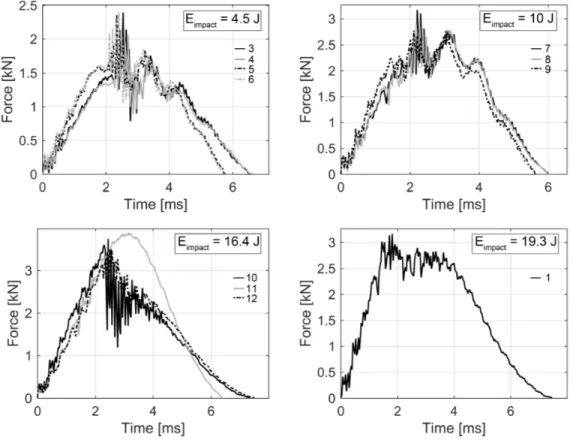
The force–time histories obtained in the impacts on the LAM16 and LAM24 specimens, sampled at 30 kHz, are shown in Figure 2 and Figure 3, respectively.
The tested specimens show mechanical responses remarkably repeatable at almost all the nominal impact energies. In 2 cases, differences in terms of mechanical behavior stand out among the LAM16 specimens:
1. the load curves of specimen 3 and 4 compared to specimen 5 and 6, tested at 4.5 J, show similar trends but smaller maximum forces and greater contact times;
2. specimen 11 presents a load curve relevantly different from the ones obtained in the impacts performed with comparable impact energy on two other specimens (specimen 10 and 12).
Figure 2: Force–time histories of the LAM16 series specimens (no data were recorded for the impact on specimen 2).
The first case depends on the fact that specimen 3 and 4 are thinner than specimen 5 and 6. In fact, the average thickness of specimen 3 and 4 was of 2.13 mm while specimen 5 and 6 were 2.55-mm thick. The second case does not depend on the geometry of the specimen (which is in line with the dimensions of specimens 10 and 12) but is related with the damage mechanisms activated during that specific impact. A more detailed discussion, supported by ultrasonic data, on the force–time history of specimen 11 is presented in Section 4.
3.1. Analysis of the force–time histories results
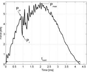
In a generic LVI force–time history curve 4 characteristic quantities can be identified [5]: 3 force values and the time for which the contact force vanishes, that is the contact time, tcont.
As an example, Figure 4 shows one of the force–time history obtained in the present LVI tests campaign. The critical force, Pcr, identifies the force for which the first relevant drop occurs. This drop is caused
by a reduction of the transverse stiffness of the laminate which can be associated to a rapid propagation of delaminations. The force decreases up to a rest load, Pr, after which, if the impactor retains enough
energy, a reloading phase occurs up to the maximum force, Pmax. Pmax depends on the residual
Figure 3: Force–time histories of the LAM24 series specimens.
The force–time histories of all the impact tests have been analyzed to evaluate the relationships between Pcr, Pmax and tcont with the nominal impact energy. This analysis is useful, in particular at the
lowest energies, where damage can be considered negligible, to evaluate possible external detrimental contributions.
In literature, extensive experimental works have pointed out how the critical force does not change with the impact energy and, moreover, is essentially independent of the boundary conditions [5, 6, 7, 8]. Then, the critical impact force, Pcr, must be reached to trigger delaminations. In [17], an analytical
expression is proposed to estimate the value of the critical impact force, Pcr:
Pcr= s 8 π2E t3 9 (1 − ν2)G c II (1)
where E and ν are the equivalent in-plane modulus and Poisson ratio of the laminate, t is the laminate thickness and Gc
II is the mode II inter-laminar fracture toughness for which a value of 700 J/m 2 has
been evaluated through dedicated ASTM end-notch flexure tests.
Figure 5 shows the comparison between the values of Pcrobtained from the experiments and the ones
computed according to Eq. 1. The analytical values of Pcr are computed by considering the measured
average thickness of each of the specimens. Since the LAM16 specimens have more scattered thickness values compared to the LAM24 ones, it follows that the standard deviations of Pcr of the LAM16
specimens (left of Figure 5) are significantly greater than the LAM24 ones (right of Figure 5). For the impacts performed at the smallest impact energies on both laminates (4.5 J and 7.3 J), the forces corresponding to the first relevant load drop are smaller than the analytical values of Pcr. In
fact, these impacts do not show relevant damage within the laminates. For higher impact energies, the experimental values of Pcr, in particular for the LAM16 specimens, are not always clearly identifiable
in the force–time histories for which remarkable differences are obtained between the analytical and the experiments. On the other hand, the results of the LAM24 specimens mostly lie within the analytical estimations of Pcr.
The experimental results show that for both laminates two values of Pcr can be identified: for the
LAM16 specimens, an average value of 2.3 kN is obtained while the LAM24 specimens exhibit an average value of Pcr around 4.2 kN.
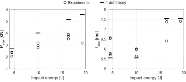
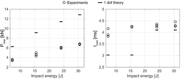
The values of Pmaxand tcontplotted in function of the impact energy are reported in Figure 6 and 7 for
the impacts on LAM16 and LAM24 specimens, respectively. The results highlight that, in particular considering the tcont values, the experiments carried out on the LAM16 specimens are more dispersed
than the ones obtained with the LAM24 ones.
The experimental results are compared with the analytical ones obtained with a 1 degree of freedom (dof) mass-spring system in which the mass, M , is the impactor mass and the spring coefficient, K, has been evaluated in FE analysis of the specimen (average dimensions) whose details are presented
Figure 5: Comparison of the analytical values of Pcr and the ones evaluated in the experimental force–time histories for
the LAM16 (left) and LAM24 (right) batch.
Figure 7: Maximum force and contact time vs impact energy of the LAM24 specimens.
in Section 5.1. The relevant relations of the analytical 1 dof system are briefly reported: Pmax= V √ KM (2) tcont= π r M K (3)
where V is the impact velocity and the values used for K are 800 N/mm and 2700 N/mm for the LAM16 average specimen and the LAM24 average one, respectively.
The comparison between the experiments and the theory is particularly interesting if the impacts performed at the smallest nominal energies (4.5 J for the LAM16 specimens and 7.3 J for the LAM24 ones) are considered. In fact, as the data obtained through ultrasonic inspections presented in Section 4 will show, the specimens impacted at the smallest energies have very small, if any, or absent delam-inations. In both cases, the expected analytical Pmaxdiffers from the average experimental one. For
the impacts on the LAM16 specimens, the difference is less than 1 kN while for the LAM24 specimens the difference increases up to more than 2.5 kN. In the same fashion, considerable differences are also obtained for the contact time. The analytical tcont are, in both cases, smaller than the ones
experi-mentally measured. The differences range between 0.5 ms for impacts on the LAM16 specimens up to around 1 ms for the LAM24 ones.
The aforementioned comparison suggests that the impactor could not be considered rigid for the tests performed with a mass of 2.5 kg. Moreover, the shape of the force–time histories of these tests (see the impacts at 4.5 J in Figure 2 and the impacts at 7.3 J in Figure 3), since the internal damage cannot be held responsible for the contact force oscillations, pose doubts on the reasons of such differences with respect of the analytical results.
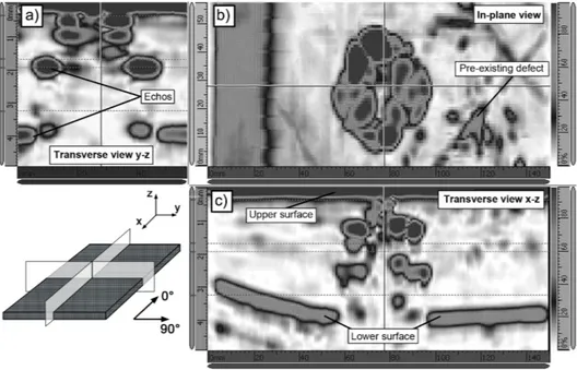
Figure 8: Example of the data obtained in the ultrasonic inspection performed on the specimen LAM24-10. Three views are displayed: the in-plane view and 2 perpendicular through-the-thickness views.
The causes of such differences are investigated and discussed in Section 5.
4. Ultrasonic inspections data
Ultrasonic inspections have been carried out, at the Canoe facilities (Bordeaux, France), on each impacted specimen through an Olympus OmniScan MX2, a portable phased array flaw detector device. Before performing the inspections of the impacted specimens, the ultrasonic device has been tuned by means of an ad-hoc manufactured specimen where defects (Teflon films) of known shape, dimensions and position within the specimen thickness were inserted during the manufacturing process.
After the tuning phase, acquisitions have been performed on each of the specimens: firstly the specimen was fixed on a flat support, then a water-based ultrasound gel was spread on the surface to be analyzed and finally the ultrasonic probe was manually moved along the specimen surface.
For each point of the scanned area, data from 3 sections of the specimen can be obtained: the in-plane section and the two through-the-thickness sections. An example is shown in Figure 8 where data obtained from the ultrasonic inspection of the specimen LAM24-10 are shown.
In the in-plane view, all the echoes revealed along the thickness are superposed and the shape and the planar extension of the damaged area can be evaluated. The transverse views give additional information about the positions of the echoes along the specified cutting planes. They also show the echoes revealed at different heights along the thickness and the upper and the lower specimen surface can be observed. The apparent curvature of the lower surface, visible in the lower–left corner of Figure
Figure 9: Results of the ultrasonic inspections of the LAM16 specimens (in-plane view). The picture frame dimensions are reported for each group of specimens.
8 (c), is produced by the small rotation of the specimen caused by the probe sliding along the x–axis. This also causes an amplification of the measured thickness variation along the x direction.
The results of all the in-plane ultrasonic acquisitions are shown, grouped according to the nominal impact energy, in Figure 9 and Figure 10 for the LAM16 and LAM24 specimens, respectively. The analysis of the in-plane view of the defects allows for a better understanding of the force–time histories shown in Figure 2. In particular, the impacts (LAM16-3/4/5/6) performed with a nominal energy of 4.5 J have already pointed out different force–time history curves caused by differences in specimen thickness. The results of the ultrasonic inspections show that the more compliant specimens (3 and 4) have more extended delaminations compared to the ones revealed on the stiffer specimens. If, on the on hand, the more compliant specimens will produce greater maximum vertical displacement which induce higher inter-laminar stress between the plies and thus more extended delaminations, on the other hand, the thicker specimens, with a greater bending modulus, will be affected by more localized damage and smaller delaminations.
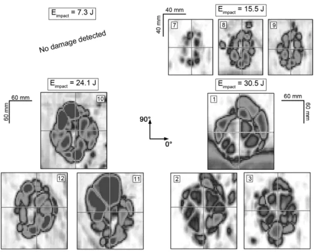
Figure 10: Results of the ultrasonic inspections of the LAM24 specimens (in-plane view). The picture frame dimensions are reported for each group of specimens.
Among the results of the ultrasonic inspections performed on the group of specimens impacted with a nominal energy of 16.4 J (LAM16-10/11/12), shown in the bottom-left corner of Figure 9, we can find the justification of the different force–time history curve exhibited by specimen 11 (see Figure 2). In fact, the revealed damage, as reported by the in-plane ultrasonic view, is remarkably different in shape and extension compared with the other two specimens which undergo analogous damage resulting in very similar force–time histories.
In particular, the ultrasonic results of specimens 10 and 12 highlight that remarkable damage along the 0◦ direction is present. Also the visual observations of the back of these two impacted specimens
confirm that longitudinal cracks are present. Conversely, specimen 11 does not present the same damage extension in the longitudinal direction either evaluating the ultrasonic results or through a simple visual inspection of the back of the specimen. To understand the source of these differences, the impact position, the geometry and the weight of the specimen (before the impact) and the impact velocity have been verified and compared with the same quantities of specimens 10 and 12. Yet no substantial differences have been noted, thus the authors believe that the behavior of specimen 11 could be ascribed to slightly higher fracture properties of this particular specimen. The presence of a smaller delaminated area is consistent with an higher maximum impact force and a smaller contact time.
Eventually, the in-plane damage observed for the LAM16 specimens tested at the higher impact energy (20 J) show damage that are remarkably similar in shape and dimensions. This suggests that even though the force–time history of the specimen 2 was not recorded, its mechanical response can be expected to be alike.
The results of the ultrasonic inspections carried out on the LAM24 specimens are similar among specimens impacted at the same nominal energy in terms of both shape and dimensions. The in-plane view shows damaged regions formed by cluster of distinct damaged areas which belongs to different positions along the thickness of the specimen. Eventually, no damage was detected within the specimens impacted at the smaller nominal impact energy (7.3 J). In this context, no damage means that, if existing, the size of the damage was below the threshold that could be evaluated through the used ultrasonic scanning device.
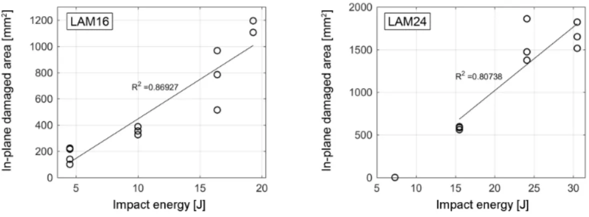
Figure 11 shows the in-plane damaged areas versus the nominal impact energies. The areas have been computed by post-processing the results of the ultrasonic inspections shown in Figure 9 and Figure 10. Many literature results [8] [17] [18] [19] show that the relationship between the dimension of the total damaged area and the impact energy of the impactor is linear. The results obtained with the LAM16 and LAM24 specimens show that even though the some results are quite dispersed the linear trend is essentially respected.
Figure 11: In-plane damaged area vs impact energy of the LAM16 and LAM24 specimens.
5. Study of the impactor assembly
This section is aimed at investigating and discussing how the impactor can be held responsible for the unexpected results obtained at the lowest energies and to suggest a method to trace back the effective energy of these impacts.
The impactor setup under investigation is the one with a total mass of 2.5 kg. The impactor setup with a total mass of 4.6 kg, due to the presence of rigid screws connecting the 2 forks, seems to produce neither unexpected experimental force–time histories nor discrepancies from the analytical results. These effects are particularly evident in the force–time histories of the tests performed at 4.5 J for the LAM16 specimens and at 7.3 J for the LAM24 specimens. In fact, it can be noted that the corresponding force–time histories present unexpected force fluctuations even if no damage (or in the case of the LAM16 specimens, negligible damage) was induced within the specimens.
Numerical analyses of the impact test have been carried out by means of a FE model whose details are thoroughly described in section 5.1. The analyses were aimed at investigating different aspects of the impact apparatus.
Preliminary investigations were focused on evaluating the effects of the clamping conditions. During the test the specimen was held still through 4 rubber clamps which were tighten as depicted in Figure 1 (c). Two clamping conditions have been evaluated in the FE model: a case the boundary conditions are enforced by directly fixing the nodes in the corresponding areas of the specimen (no vertical displacement allowed) and another case where the constraint is modeled through contact interactions between the rubber clamps and the specimen. In the latter case, two materials models have been tested: a linearly elastic model and an hyper-elastic one.
To evaluate the numerical stiffness of the laminate with its boundary conditions, a vertical displacement is applied to the center of the specimen and the reaction force is extracted. The results showed that
Figure 12: Representation of the FE model with the enforced boundary conditions on the left and details of the mechanical behavior of the connector elements on the right.
the differences between the numerical stiffnesses of the three clamping modes is less than 8%.
In all the simulations that will be presented, the simpler boundary conditions have been used since they foster convergence (no additional contact interactions) while providing a good approximation of the specimen stiffness.
5.1. Finite element model of the impact test
Figure 12 shows the FE model of the impact test setup. The model reproduces all the main compo-nents: the impactor, the specimen held by clamps and the steel support. The impactor is constituted by two aluminum forks and three aluminum plates. The forks, the magnet and the force sensor system have been modeled through solid elements (C3D8) while continuum shell elements (SC8R) have been used to model the plates which connect the forks.
The contact force is obtained by using a spring element which has been characterized with data taken from the sensor datasheet (K = 1800 kN/mm). The lateral guiding steel columns are reproduced in the FE model by directly applying boundary conditions on sets of nodes of the forks.
The specimen, modeled with two continuum shell elements in the thickness, is sustained from the bottom by a steel support of C3D8 elements, 4 rubber clamps hold the specimen down while 3 guiding pins avoid lateral movements. The rubber clamps are modeled with C3D8 elements while the guiding pins are rigid cylindric surfaces in contact with the sides of the specimen.
The focus of this investigation was directed toward a realistic characterization of the bolts that con-nected the forks and the plates. In order to handle complex mechanical behaviors, connector elements [15] have been adopted to model the bolted connections. The bolts are represented in the FE model via connector elements which permit the definition of user-defined mechanical models relating axial and shear bolt forces vs corresponding relative displacements. Connector elements link group of nodes, belonging to the plates and to the forks, identified by assigning an influence radius for the connector. Figure 12 (right) explains how local directions are specified and qualitatively shows the assigned me-chanical models. Two kinds of connector behaviors have been devised: a linear relationship for the y local direction and a bi-linear one for the x and z local directions.
The linear behavior along the local y direction is used to assign the appropriate axial stiffness of the bolts and, at the same time, to prescribe a preload to each bolt. The bi-linear curves used to charac-terize the x and z local directions model the possibility of a relative sliding between the forks and the plates.
Eventually, contact interactions between adjacent components were characterized with a friction coef-ficient of 0.1 which, in combination with the assigned bolts preload, is able to hinder bolts sliding up to a certain axial load.
5.2. Modal analysis
A modal analysis has been performed with the FE model of both the specimen (24 plies) and the impactor employing rigid bolt connections. The simulation consists of 2 steps: in the first step, the impactor is moved to close the initial gap with the specimen, then, in the second step, the natural frequencies of the system are extracted.
From the modal analysis, 3 global modes mainly involving the longitudinal motion of the impactor parts and of the specimen, have been selected and shown in Figure 13.
Oscillations with frequencies close to that of the first mode (538 Hz) can be observed, when contact time exceeds 2 ms, in the force signals of tests on the LAM24 specimens at 7.3 J and 15.5 J (see Figure 3). Yet, the results of the modal analysis of the rigidly connected impactor does not explain the unexpected force fluctuations obtained in the impacts performed with the lowest impact energy (LAM24 specimens).
The possibility of an imperfect tightening of the bolts suggested that the upper and the lower forks could be acting as separated bodies for a certain time interval (contact time less than 2 ms), thus reducing the active impactor mass. To verify such hypothesis, a modal analysis of the lower fork and the specimen has been carried out.
This analysis shows a first vibration mode, in which only the specimen vibrates, at about 248 Hz. This result is consistent with the frequency of the carrier wave, of about 250 Hz, that can be recognized in
Figure 13: The 3 vibrational modes extracted from the modal analysis.
7.3 J impact test for contact times between 0 and 1.5 ms.
In the light of these preliminary results, it can be concluded that a sliding between the lower fork and the plates occurs due to an imperfect tightening of the bolts. In this scenario, the relevant high-frequency force fluctuations, visible in Figure 2 (4.5 J impact) around 2.5 ms and in Figure 3 (7.3 J impact) around 1.9 ms, could be induced by the gap closure between the lower forks and the system formed by the upper forks and the plates.
Then, the force–time histories of these impacts can be interpreted and described by considering 3 consecutive phases:
1. the first part, where the force increases steadily, is associated with the impact of the lower fork mass, at the given initial velocity, with the specimen;
2. once the entire gap of the bolts connecting the lower fork and the plates has been closed, high-frequency force oscillations are generated and rapidly damped out by the system;
3. finally, the impact continues with an active impactor mass given by the sum of the masses of the lower fork, the plates and the upper fork.
In order to substantiate this hypothesis of consecutive events, detailed simulations of impact tests are presented in the following section. A numerical-experimental approach to evaluate the effective energy of these impacts is then presented in Section 5.4.
5.3. Results of the numerical analyses
Even though no data were available about the bolts preload, measurements carried out, at a later time, on the impactor has revealed that the bolts were able to slide of about 1 mm. Thus, this value
Figure 14: Force–time history comparison between the experiments and the numerical results obtained with the same impact apparatus setup in impact tests at 4.5 J and 7.3 J on the LAM16 and LAM24 average specimen, respectively.
has been assigned to the parameter U0 reported in Figure 12 as the relative displacement threshold
in the bilinear constitutive curve of the x and z local directions. Moreover, the connector elements were set in order to provide, at the beginning of the impact, a bolt preload equal to 1 kN for the bolts connecting the fork at the bottom of the impactor and equal to 4 kN for the ones at the top. This choice reflects the hypothesis that the plates and the upper fork are the first to slide on the lower fork. Figure 14 shows the results of the simulations of both the 4.5 J and the 7.3 J impact tests.
The relevant mechanisms which explain the unexpected curves are reproduced and, in fact, after a first interval in which the force grows steadily (impact of the lower fork mass with the specimen), the contact force suddenly increases due to the gap closure of the bolts of the lower fork.
Yet, in the experiments the relevant force fluctuations are of smaller magnitude, with an higher fre-quency and are damped out more rapidly. The differences between the magnitude of the experiments and of the simulations can be attributed to factors such as: no damping is present in the simulations, the values of shear stiffness used for the bolts could be smaller (this would modify the amplitude of the contact force fluctuations) and, eventually, the properties assigned to contact interactions could modify the response (value of the static friction coefficient and introduction of a dynamic friction coefficient). Nonetheless, since the predicted contact times match closely the experimental ones, it can be safely assumed that the simulations are able to capture the main physical aspects of the impact mechanical response.
5.4. Considerations on the effective impact energy
In the light of the results of the numerical analyses, the nominal impact energies of the tests performed with the impactor setup with a total mass of 2.5 kg (see Table 2), cannot be considered as their effective ones. Differently, the results obtained for the tests carried out with the 4.6 kg impactor are not affected by the presented dissipation mechanisms since the sliding phenomena are prevented
thanks to the long screws used to fix the additional masses (see Figure 1 (a)).
In this section, a numerical-experimental approach, based on energy considerations, is proposed to evaluate the effective impact energy for such tests.
In an ideal scheme, the impactor would be significantly stiff with concentrated mass in order to store negligible elastic energy and to transfer its kinetic energy to the specimen. In this case, ineffective connections between components together with internal dissipation mechanisms absorb initial kinetic energy quotas reducing the effective impact energy.
During an ideal impact (no damage), all the initial kinetic energy is transformed into elastic energy of the specimen. In the analyzed impacts, to evaluate the effective impact energy, the value of the elastic energy stored into the specimen has been extracted as an indirect output from the FE analyses. Effective is to be intended as the actual energy transferred into the specimen. Even though the simplification could seem brutal, it is worth remembering that the specimens impacted with a nominal energy of 4.5 J as well as as the ones impacted with 7.3 J have presented negligible or absent damage. Thus, the total energy balance applied at the beginning and at the end of these impacts would state:
EK0impactor = ET OTf
impactor+ E f
T OTspecimen − Edissipated (4)
where E0
Kis the kinetic energy at the beginning of the impact and E f
T OT = E f K+E
f
Eis the total energy,
sum of kinetic and strain energy, at the end of the impact. Eventually, Edissipatedf is the sum of all the energy dissipated during the impact and could contain contributions due to dissipative mechanisms, such as friction or internal damage, coming from both the impactor and the specimen.
Thanks to the performed FE analyses, an evaluation of Edissipatedf can be obtained indirectly through the numerical evaluation of the total kinetic energies as well as the total strain energy of both the specimen and the impactor. Then, the effective impact energy can be computed as stated in Eq. 5.
Eimpactef f ective= EK0impactor− Edissipatedf (5) Figure 15 shows the kinetic and strain energy time histories obtained from the FE simulations of both the impactor and the specimen. The difference of the impactor kinetic energy (black continuous line) at the beginning and at the end of the simulations is in both impacts significant while negligible kinetic and strain energy is present within both the impactor and the specimen at the end of the impact. Since no damage (or negligible) damage was induced during the experiment within the specimen and since the numerical simulations well reproduce the experimental curves, the difference in kinetic energy must be attributed to the dissipation mechanisms acting within the impactor and the effective impact energy can be evaluated for these tests.
For the impacts at 10 J (LAM16) and 15.5 J (LAM24) the same approach cannot be used since the ultrasonic inspection revealed the presence of internal damage (see Figure 9 and Figure 10).
Figure 15: Kinetic and strain energy of both the impactor and the specimen evaluated with the FE simulations of the 4.5 J impact on the LAM16 average specimen and of the 7.3 J impact on the LAM24 average specimen. In both simulations the kinetic energy of the specimen is negligible (continuous gray curves superposed to the horizontal axes).
In order to provide an evaluation of the effective impact energies, without performing simulations where the damage was needed to be reproduced (i.e. progressive failure analyses), a combined numerical-experimental approach is used to trace back the value of the dissipated energy, Edissipatedf , of the impacts at 10 J (LAM16) and 15.5 J (LAM24) from the maximum force measured in the tests. This approach consists in two steps: in the first step, a numerical baseline curve (one for LAM16 and one for LAM24), relating the Edissipatedf and the maximum force, is created by performing 3 simulations at increasing impact energies with the same impactor setup; then, in the second step, the experimental maximum force is used to estimate the value of Edissipatedf . For the first step, the selected impact energies for the FE simulations are 1.25 J, 4.5 J and 10 J for the LAM16 laminate and 1.25 J, 7.3 J and 15.5 J for the LAM24 one. In the second step, the experimental maximum force is the average value of the maximum forces obtained in the 3 impact tests performed on the specimens of both LAM16 and LAM24 series.
In Figure 16, the numerical baseline curves of LAM16 and LAM24 laminate are shown together with the representation of how the experimental average maximum forces of the impacts at 10 J (LAM16) and at 15.5 J (LAM24) are used to evaluate the value of Edissipatedf .
The new impact energy scenario obtained through the evaluation of the effective impact energy of the impacts performed with the impactor of 2.5 kg is reported in Table 3. The comparison between the nominal and effective energy points out that while for the thin specimens (LAM16) the ratio between the effective energy and the nominal energy, Eef f ective
Enominal, is essentially constant about 0.7; for the thick
Figure 16: Extrapolation of the values of the Efdissipatedof the impacts of 10 J (LAM16) and 15.5 J (LAM24).
LAM16 Nom. Energy Eff. Energy LAM24 Nom. Energy Eff. Energy
ID [J] [J] ID [J] [J]
3/4/5/6 4.5 3.1 4/5/6 7.3 2.9
7/8/9 10.0 7.0 7/8/9 15.5 10.9
Table 3: Effective impact energies compared with the nominal ones.
again, 0.7 for the impacts with Enominal equal to 15.5 J.
With the new scenario of effective impact energies, the relationship between the impact energy and the in-plane damaged area can be reinterpreted. If the effective values are used, the relationship between the in-plane damaged area and the impact energy is better approximated by a linear law, as shown in Figure 17.
6. Post-impact indentation depth
In the design of a damage tolerant structure, the damage threat assessment is fundamental in order to evaluate the different damage scenarios occurring during manufacture, operation and maintenance. Particular care is given to the structure inspectability since inspection intervals should be established, considering both the likelihood of a particular damage and the residual strength capability associated with this damage.
In this context, the threshold of reliable detection is named Barely Visible Impact Damage (BVID), typically associated with an indentation depth below 0.5 mm [20]. Damage, lower than the BVID,
Figure 17: Linear correlation of the in-plane damaged area vs the impact energy, for the impact tests on the LAM16 and the LAM24 specimens, when the nominal energies (in black) and the effective ones (in gray) are considered.
must not reduce the strength of the structure below its ultimate load capability [1].
To investigate the relationship between the indentation depth and the impact energy, the impacted spot of each of the 24 specimens has been identified and marked. Then an high resolution laser micrometer which was able to move along 2 axes has been used to measure the indentation depth.
The laser was moved with 2 brush-less motors which were remotely controlled by a LabVIEW script which moved the laser with a spatial resolution of 0.5 mm along the two axes. The laser could span an area of dimensions 20 × 20 mm centered around the impact spot of the specimen surface.
Figure 18 shows, in its left part, 2 examples of acquisitions, performed on both a LAM16 specimen and a LAM24 one, in which the spatial resolution as well as the covered area can be appreciated. In Figure 18, the z-axis scale represents the distance between a generic point of the scanned area and the mean plane.
The indentation depth measured on the inspected specimens has been correlated with the corresponding impact energy as reported in the right part of Figure 18. The data obtained for the LAM16 specimens are more dispersed than the ones obtained for the thicker LAM24 specimens. The maximum depth obtained for the LAM16 specimens is around 0.25 mm with an impact energy of 19.3 J while for impacts of 30.5 J on the LAM24 specimens the maximum indentation measured was of around 0.15 mm. The measurements of the indentation depth reveal that all the damage are below the BVID threshold.
7. Conclusions
This paper presents the results of an experimental campaign of LVIs performed on 2 batches, of 12 specimens each, of quasi-isotropic carbon/epoxy laminates, one with 16 plies (LAM16) and one with 24 plies (LAM24).
Figure 18: Examples of 2 results elaborated from the laser readings for a LAM16 and a LAM24 specimen (left) and maximum indentation depths evaluated for each of the 24 specimens (right) compared with the effective impact energy.
For each of the batches, 4 nominal impact energies were selected to obtain damage scenarios of in-creasing severity. To limit the impact velocities at the higher energies, 2 impactor masses of 2.5 and 4.6 kg were used.
Among the impact tests performed at the same nominal impact energy, the contact forces measured over time was very repeatable and from each of them, the maximum forces, the contact times and the delamination threshold loads were evaluated. The LAM16 specimens have an average DTL of 2.3 kN, which is greater than the analytical prediction, while the average DTL value for the LAM24 batch is 4.2 kN, in agreement with the analytically predicted value.
Each of the impacted specimens has been then inspected with a phased array ultrasonic scanner to evaluate the shape and the extension of the damage at the different impact energies and to compute the projected delaminated areas. The projected delaminated areas was found to be linearly dependent on the impact energy, in agreement with literature results.
To complete the experimental acquisitions, 3D scans of the surface were carried out for each specimen and the indentation depth evaluated.The results showed that all the impacts were below the BVID threshold (0.5 mm).
The comparison of the force–time histories of the tests performed with the lowest impact energies (4.5 J for the LAM16 batch and 7.3 J for the LAM24 batch) with analytical results and with the data of the ultrasonic inspections highlighted unexpected results. In fact, significant force oscillations were present even if no damage (or an extremely localized one) was revealed. Moreover, both the maximum forces and the contact times were significantly different from the analytical predictions. With the purpose of determining the causes of these discrepancies and to trace back the effective impact energy for these impacts, a detailed FE model of the test was created. The results pointed out that the 2.5 kg impactor mass setup, due to internal bolts slidings caused by an imperfect tightening, dissipated part of the initial kinetic energy of the impactor. Then, to estimate the effective impact energy, a numerical-experimental approach was used and the energies of the impacts involving the anomalous impactor setup were corrected.
The produced database comprises experimental information about different aspects of LVI tests (con-tact forces, DTLs, ultrasonic maps and indentation depths). These LVI data would prove useful as a benchmark for the development of numerical damage models to be used in simulations aimed to determine the residual strength of damaged structures. The specimens subject to LVI tests presented in the paper will be used in a compression after impact campaign scheduled to provide experimental reference data for the simulations.
8. References
[1] European Aviation Safety Agency, Certification specifications, General Acceptable Means of Com-pliance for Airworthiness of Products, Parts and ApCom-pliances, 26 July 2010, AMC20-29.
[2] Minak G. and Ghelli D., Influence of diameter and boundary conditions on low velocity impact response of CFRP circular laminated plates. Composite Part B 39 (2008) 962–972.
[3] Artero-Guerrero J.A., Pernas-Snchez J., L´opez-Puente J. and Varas D., Experimental study of the impactor mass effect on the low velocity impact of carbon/epoxy woven laminates. Composite Structures 133 (2015) 774–781.
[4] Guillaud N., Froustey C., Dau F. and Viot P., Impact response of thick composite plates under uniaxial tensile preloading. Composite Structures 121 (2015) 172–181.
[5] Carti´e D.D.R. and Irving P.E., Effect of resin and fibre properties on impact and compression after impact performance of CFRP. Composites Part A 33 (2002) 483–493.
[6] Schoeppner G.A. and Abrate S., Delamination threshold loads for low velocity impact on com-posite laminates. Comcom-posites Part A 31 (2000) 903–915.
[7] Zhang X., Hounslow L. and Grassi M., Improvement of low-velocity impact and compression-after-impact performance by z-fibre pinning. Composites Science and Technology 66 (2006) 2785–2794. [8] Davies G.A.O. and Zhang X., Impact damage prediction in carbon composite structures.
Inter-national Journal of Impact Engineering 16(1) (1995) 149–170.
[9] Abrate S., Impact on composite structures. Cambridge University Press, 1998.
[10] De Freitas M. and Reis L., Failure mechanisms on composite specimens subjected to compression after impact. Composite Structures 42 (1998) 365–373.
[11] Remacha M., S´anchez-S´aez S., L´opez-Romano B. and Barbero E., A new device for determining the compression after impact strength in thin laminates. Composite Structures 127 (2015) 99–107. [12] Ghelli D. and Minak G., Low velocity impact and compression after impact tests on thin
car-bon/epoxy laminates. Composites: part B 42 (2011) 2067–2079.
[13] Karbhari V.M. Editor, Non-Destructive Evaluation (NDE) of Polymer Matrix Composites. Wood-head Publishing, 2013.
[14] Longo G., Models and methods to simulate low-energy impact damage on composite aerospace structures, Ph.D. thesis, University of Pisa, 2011.
[15] Dassault Systemes Simulia Corp., Abaqus 6.11, User’s Manual, 2011.
[16] ASTM D7136-07, Measuring the damage resistance of a fiber-reinforced polymer matrix composite to a drop-weight impact event, 2007.
[17] Davies G.A.O. and Robinson P., Predicting failure by debonding/delamination. In: Debond-ing/Delamination of Composites. AGARD Conference Proceedings 530, Neuilly sur Seine: AGARD, 1992, p. 5.1–5.28.
[18] Abrate S., Impact on Laminated Composite Materials. Applied Mechanics Reviews 44 (4) (1991) 155–190.
[19] Cantwell W.J. and Morton J., Comparison of the low and high velocity impact response of CFRP. Composites 20 (6) (1989) 545-551.
[20] Rouchon J., Fatigue and damage tolerance evaluation of structures: the composite materials response. 22ndPlantema Memorial Lecture, ICAF Symposium, Rotterdam 2009.