HAL Id: pastel-00646962
https://pastel.archives-ouvertes.fr/pastel-00646962
Submitted on 4 Dec 2011HAL is a multi-disciplinary open access archive for the deposit and dissemination of sci-entific research documents, whether they are pub-lished or not. The documents may come from
L’archive ouverte pluridisciplinaire HAL, est destinée au dépôt et à la diffusion de documents scientifiques de niveau recherche, publiés ou non, émanant des établissements d’enseignement et de
Ligands
Alexandre Garcia
To cite this version:
Alexandre Garcia. Métallisation Electroless des Polymères Induite par des Ligands. Matériaux. Ecole Polytechnique X, 2011. Français. �pastel-00646962�
Laboratoire de Chimie des
Surfaces et Interfaces
Thèse de doctorat de l’École Polytechnique
Spécialité : Science des matériaux
Présentée par
Alexandre GARCIA
Ligand Induced Electroless Plating of Polymers
Métallisation Anélectrolytique des Polymères Induite par
des Ligands
Soutenance prévue le 19 Septembre 2011 devant le jury composé de :
Pr. Jean-Christophe LACROIX Université Paris Diderot Rapporteur
Pr. Pascal MAILLEY Université Joseph Fourier Grenoble Rapporteur
Pr. Clément SANCHEZ Collège de France / Université de Pierre et Marie Curie Examinateur
Dr. Thierry GACOIN Ecole Polytechnique Examinateur
Dr. François BESSUEILLE Université Claude Bernard Lyon Examinateur
Ce travail de thèse a été réalisé au Laboratoire de Chimie des Surfaces et Interfaces (LCSI) du Service de Physico-chimie des Surfaces et Interfaces (SPCSI) du CEA de Saclay en collaboration avec le Laboratoire des Solides Irradiés (LSI) au CEA et basé à l’Ecole Polytechnique.
Je tiens tout d’abord à remercier Serge Palacin qui m’a accueilli au LCSI et m’a fait entièrement confiance tant dans la réalisation de mes travaux que dans la rédaction et la présentation des résultats notamment lors de conférences internationales (Cancun, Mexico). Merci Serge pour tes conseils, tes lectures et relectures de nos différents articles et de mes chapitres de thèse. Je remercie, avec émotion, mon directeur de thèse, Pascal Viel, toujours disponible et prêt pour parler des projets à venir, des résultats obtenus mais également de gloire, d’amour et d’eau fraîche… Et tout ça, quelque soit le jour avec grande générosité, une énorme envie et confiance. Chef, allias Maman, ces trois ans à tes côtés resteront pour moi une période incroyablement enrichissante. Je remercie profondément, mon encadrant de thèse, Thomas Berthelot, également toujours disponible et prêt à bâtir l’avenir, toujours aller plus haut et croire en l’avenir! Le tout avec volonté,
passion et envie de toujours faire mieux, viser plus haut!
Chef, allias Papa, ces trois ans où tu m’as emmené avec toi d’un laboratoire à un autre furent une vraie réussite et je pense qu’elle restera mutuelle.
Je remercie grandement Bruno et Jérôme qui m’auront apporté tout leur expérience, savoir et patience donnant lieu à une très belle production de résultats…Un grand merci Messieurs!
Je tiens à remercier tout particulièrement mes collègues et amis du LCSI, qui par leur bonne humeur, leur esprit d’équipe et leur ouverture d’esprit ont rendu ces trois années inoubliables. Alice ma Jumelle (ou binôme), on aura bien rigolé, voyagé, partagé les pires comme les meilleurs moments! Encore merci pour ton organisation, dont il faut le dire, j’ai souvent largement profité, et surtout bon suite, comme dirait un autre compère, Federico !
Fanny, Maman dans l’âme, merci encore de la part ton fiston pour tous ces précieux conseils et autre fous rires !
Lorraine et Romain, vous avez été les piliers sur lesquels j’ai pu compter à mon arrivée et vous resterez toujours dans mon cœur.
Xavier et Adina, chers co-bureaux, merci pour toutes ces conversations endiablées autour du sport, du PSG mais aussi autour de Dalida et des complexes metalliques… Et je n’oublierai pas non plus votre soutien au quotidien, ces 2 ans en votre compagnie furent vraiment agréables !
Merci à Guy le conseiller vacances, Pascale la cacheuse d’échantillons et experte en XPS, Brigitte toujours prête à rendre service, Nabila pour tous nos fous rires et blagues , Tuan mon mentor, Amandine la copine chez les physiciens, Cécile, Olivier, Julienne, Dimitry, Cédric et les stagiaires comme on les aime Nassim, Robin (à prononcer à l’anglaise), Jenna, Mohamed, Marianne et les naines de Montpellier…
Merci à ma famille qui est toujours resté à l’écoute dans les bons comme les mauvais moments, ça y est j’y suis arrivé.
Enfin, Merci à Pauline, ma louloute d’amour, pour ton soutien tous ces jours et en particulier les derniers. Merci pour ton investissement au quotidien, je n’aurai pas pu rêver meilleur support et meilleure moitié…
Table of contents
ABBREVIATIONS, NOTATIONS, ACRONYMS ... 5
I. INTRODUCTION ... 7
II. STATE OF THE ART ... 17
1. SURFACE CONDITIONING OR PRETREATMENT ... 19
1.1. Mechanical pretreatments ... 21
1.2. Chemical pretreatments ... 21
1.3. Physical treatments ... 23
1.4. Conclusions ... 23
2. METALLIZATION/METAL PLATING OF POLYMERS ... 23
2.1. Solid and molten metal based deposition ... 23
2.2. Gaseous phase based metal deposition (Dry process) ... 24
2.3. Solution based metal deposition: Electroless metal deposition (Wet process)... 25
2.4. Alternative method: Jet-Metal™ technology ... 42
3. ELECTROLESS PLATING OF PDII-LIGAND MODIFIED POLYMERS ... 43
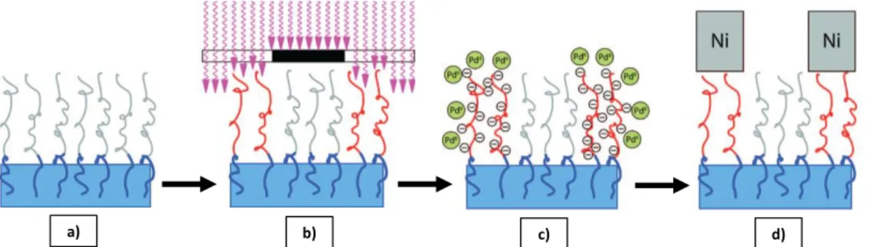
3.1. Surface functionalization by SAM adsorption (2D-ligation) ... 44
3.2. Surface functionalization by dried treatments (2D/3D-ligation) ... 48
3.3. Surface functionalization by surface graft polymerizations (3D-ligation) ... 49
3.4. Polymer surface swelling as host polymer film: The polyamide case ... 52
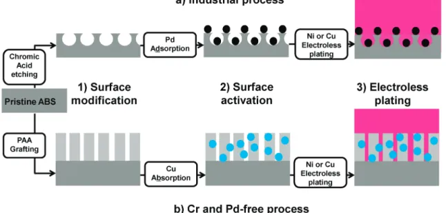
3.5. Pd-free Electroless plating of polymers ... 53
3.6. Conclusions ... 53
4. METHODS USED FOR THE LOCALIZED METAL DEPOSITION ... 53
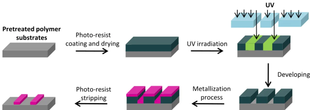
4.1. Photolithography based process ... 54
4.2. Printing techniques ... 55
4.3. Conclusions ... 59
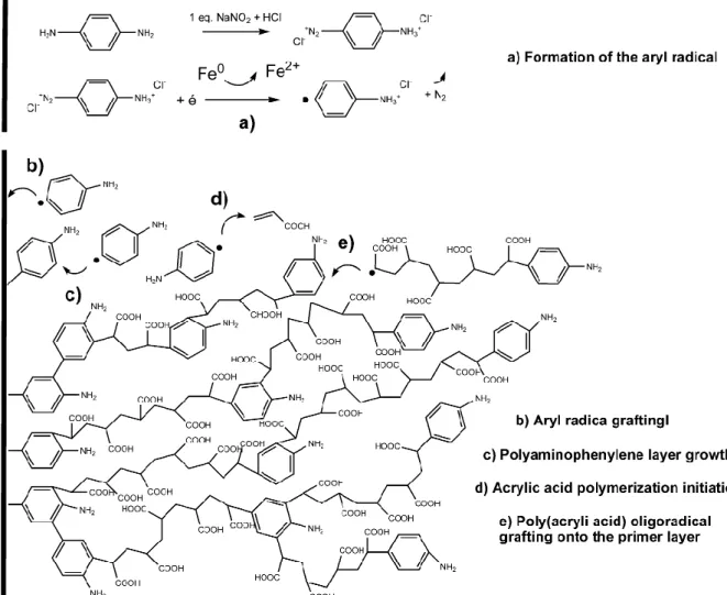
5. DIAZONIUM INDUCED ANCHORING PROCESS “DIAP” - GRAFTFAST™PROCESS ... 60
5.1. Graftfast™ origin ... 60
5.2. Graftfast™ components and mechanism... 61
5.3. Graftfast™ versatility ... 66
5.4. Conclusions ... 70
2. MICROSCOPIC STUDY OF THE LIEP PROCESS THROUGH ITS APPLICATION ONTO VARIOUS SUBSTRATES ...99
3. SURFACE AND INTERFACE ISSUES ...121
4. LIEP PROCESS FOR THE METALLIZATION OF A COMPLEX SHAPED OBJECT AND MADE OF DIFFERENT MATERIALS ...122
IV. LOCALIZED LIEP VIA LITHOGRAPHIC BASED METHODS ... 123
1. INTRODUCTION ...125
2. FABRICATION OF MICROMETRIC COPPER PATTERNS ONTO PET AND PVDF SHEETS ...125
V. LOCALIZED LIEP VIA THE GRAFTFAST™ PROCESS BY PROJECTION OR TRANSFER ... 141
1. INTRODUCTION ...142
2. LOCALIZED LIEP VIA AN INKJET-PRINTED AND PHOTO-ASSISTED GRAFTFAST™ PROCESS ...143
VI. ALTERNATIVE PROCESS: LOCALIZED AMINO-INDUCED ELECTROLESS PLATING ... 167
1. INTRODUCTION ...169
2. LOCALIZED AMINO-INDUCED ELECTROLESS PLATING PROCESS ...170
VII.GENERAL CONCLUSION AND OUTLOOKS ... 187
Abbreviations, Notations, Acronyms
A) Molecules and Polymers
4VP 4-vinylpyridine
ABS Acrylonitrile-Butadiene-Styrene
ABS-PC Acrylonitrile-Butadiene-Styrene-Polycarbonate DNA Deoxyribonucleic acid
EDTA Ethylenediaminetetraacetic acid FPI Fluorinated polyimide
GOD Glucose oxidase
PA PolyAmide
PAA Poly(acrylic acid)
PAMAM Polyamide-amine
PAP Polyaminophenylene
PE Polyethylene
PET Poly(ethylene terephtalate) PDMS Polydimethoxysilane PHEMA Polyhydroxyethylmethacrylate PS Polystyrene PP Polypropylene PVC Poly(vinyl chloride) PVDF Poly(vinylidene fluoride) VIDz Vinylimidazole
B) Characterizations
AFM Atomic Force Microscopy
IR Infra-Red
RF Radio-Frequency
UV Ultra Violet
VUV Vacuum Ultra Violet
XPS X-ray photoelectron spectroscopy
C) Processes
AIEP Amino-Induced Electroless Plating process CIJ Continuous Inkjet Printing
CVD Chemical vapor deposition
DIAP Diazonium Induced Anchoring Process
DOD Drop-on-demand
LIEP Ligand Induced Electroless Plating µCP Microcontact printing
PVD Physical vapor deposition
SEEP Surface Electroinitiated Emulsion Polymerization
D) Others
ASTM American Society for Testing and Materials
In everyday life, we are surrounded by products and materials that are coated by thin films which main goal is to combine the properties of the bulk material and the coating. Obviously, while using their smart phone, their computer or their car, customers cannot imagine the innovative breakthroughs that were achieved to develop and industrialize these attractive products. One of the main challenges for manufacturers is to ensure the performance durability with time. This performance is driven in part by adhesion and cohesion mechanisms. Therefore, while cohesion is depending on the intrinsic properties of the coating material, the adhesion between two materials is based on physical, chemical and mechanical interactions between those materials. And even if from the Neolithic period, coatings made of beeswax or Arabic gum have been used to give new chemical or physical properties to raw materials, we are still not able to explain exactly all the phenomenon involved in the adhesion mechanisms. The famous Geckos lizards are a good illustration of the adhesion mechanism complexity (Figure 1). Hence, they are able to run up a wall and hang onto ceilings of most surfaces thanks to their footpads made of spatula tipped setae which own incredible adhesive forces. Even if it was admitted that these adhesive forces are mainly based on Van der Waals interactions between the adhesive setae and the surface, complete adhesion mechanisms are still not fully understood and controversial [1-3].
Figure 1 : Pictures of a gold dust day gecko (also known as Madagascar day geckos) and a close-up of the underside of a gecko's foot as it walks on vertical glass
However, scientific community concurs to say that adherence of a coating onto a surface is the result of a very complex balance between mechanical and physico-chemical interactions between the surface and the coating that need to be optimized. This is specifically true for coatings which do not have any specific chemical or physical affinity with the raw material surface to be coated, such as metal coatings onto plastics substrates.
As such, since the end of the Second World War the use of plastics substrates has hugely increased due to their specific properties such as light weight, design flexibility and low cost of manufacturing. This has led, in a very wide range of applications, to the replacement of metals with polymers as materials of construction. Nevertheless, they are several metal properties that cannot be matched by polymers such as the reflectivity, brightness or electrical conductivity. This was a drawback when, in the early 1960’s, the automobile industry was looking to replace metal with polymer substrates for manufacturing exterior and interior bright trim. At this moment, trim components were usually finished in bright electroplated nickel/chromium generally known as chromium electroplating, which provided the required high quality brightness. If plastics substrates were used as a replacement, a new coating method was therefore required to provide similar surface appearance and properties. It was soon established that only electroplated nickel/chromium would give the necessary quality that was related not only to aesthetic properties but also to other properties of this particular coating system such as good resistance to corrosion and abrasion, or ease of cleaning. The surface coatings industry was facing the problem of producing this durable and attractive metal coating on polymers components, thereby combining the advantageous properties of the substrate with those of the coating system.
Contrarily to polymer coatings onto metals that can be obtained by electrochemical or chemical processes, metal coatings onto insulating substrates such as polymers was a great challenge since very few chemical or electrochemical processes are available to promote the adhesion of a metal onto insulating polymer substrate. Additionally, the mechanical constraints generated by an inelastic metal layer onto a flexible and elastic polymer are quite high and make the process quite difficult to optimize and durability of the final coatings difficult to improve.
However, since the early days of the 1960’s, the economic and technological attractiveness of the metallization (or metal finishing) of polymers & polymer-based materials has led to the development of various processes and is widely used today in various technological applications ranging from decorative coatings in general manufacturing and especially in the automobile industry to the fabrication of printed circuits in microelectronics (Figure 2) [4-10]. Indeed, the use of organic materials combined to metal coating in the fabrication of
microelectronics devices, bioelectronics devices and portable electronics has met a growing interest during the last few decades [10-16]. As an example, the fabrication of metallic circuit patterns on polymer substrates becomes extremely important for the manufacturing processes of flexible electronics.
Figure 2 : Examples of polymer metallization applications
Up to now, for ABS Styrene), ABS-PC (Acrylonitrile-Butadiene-Styrene-PolyCarbonate) and PA (PolyAmide), which represent more than 90 % of the industrially metallized polymers (Figure 3), the best (and most widely used) method is based on the electroless metal plating growth. This process starts by a chromic acid etching, which oxidizes the bulk polymer surface. In most cases, this surface conditioning (or surface treatment) is followed by the surface seeding with a catalyst and the electroless deposition itself, which is the chemical deposition of a metal film from a solution containing a mild reducing agent and an ionic complex of the metal to be plated onto the seeded substrate [6,
Automobile industry 53% Health 25% Perfurmery10% Electronics 5% Fashion accessories 1% Domestics Electronics1% Sundries 5%
9]. The main goal of the electroless deposition is to make the polymer substrates conductive (0.5 to 2 µm in thickness) and then, depending on the applications, various metal electroplating steps are achieved. Finally, the thickness of the metal coating is about a few tens microns which induces strong surface mechanical strains. Therefore, the ability of the whole metal coating to withstand mechanical strains is directly linked to the adhesion of the electroless metal layer onto the substrate. And that is how the hexavalent chromium based surface treatment step is essential in the metallization of polymers process since it is the step that guarantees the adhesion of the electroless metal layer and thereby the adhesion of the metal coating including the different electroplated layers [9, 17, 18].
Figure 3 : Metal plated polymers distribution
Unfortunately, hexavalent chromium or chromium (VI) which is also essential for other surface treatments processes such as chromic acid anodizing [19] or hard chromium electroplating [20] is highly toxic by inhalation and is a proven carcinogen. Breathing high levels of hexavalent chromium can damage and irritate nose, lungs, stomach, and intestine (US Agency for Toxic Substances and Disease Registry, 1993). Risks linked to chromium trioxide or chromic acid based solutions are given by the INRS (Institut national de recherche et de sécurité) safety sheets. Although hexavalent chromium provides many advantageous properties, it is regulated by the European Council for its toxicity and carcinogenicity [17, 18]. As a matter of fact, hexavalent chromium waste can be generated by either industrial accidental leak or landfill products.
In order to prevent any environmental accident during the metallization process, hexavalent chromium concentration in the industrial baths and their volumes are important
ABS 50% PP 3% Exotic Products 2% ABS-PC 42% PA 3%
factors for the industrial plants classification based on the ICPE nomenclaturea, the French equivalent European directive called, “SEVESO II”b [21]. More recently, another European directivec aims to prevent and reduce all recurrent pollution risks produced by the most polluting European plants (chemistry, metallurgy, papermaking, mechanical industry, glassworks but also industrial livestock farming …) by increasing the use of "best available techniques" (BATs) which is an obligation to ensure that industrial operators work with the most cost-effective techniques to achieve the highest level of environmental protection [22]. Besides, according to the BATSs for the waste treatment described in the BAT REFerences document (BREF), hexavalent chromium is banned from the waste and has to be reduced in trivalent chromium.
For landfill products, legislations refer to two similar European directives [17, 23].d,e
As a matter of fact, through all these directives, the main goal is to ban hexavalent chromium from all consumer products (in automobile industry and electrical and electronic equipments) which end-life cycle is not yet fully controlled and limit its use during the process fabrication.
Finally, in the near future, the European Commission Regulation N°143/2011 of 17 February 2011 amending Annex XIV to Regulation (EC) N°1907/2006 of the European
aInstallations classées pour la protection de l’environnement - Inspectorate of Classified Installations b Directive 1996/82/EC of the European parliament and of the council of 9 December 1996 on the
control of major-accident hazards involving dangerous substances
c
Directive 2008/1/EC of the European Parliament and of the Council of 15 January 2008 concerning Integrated Pollution Prevention and Control, which replaces the Council Directive 96/61/EC of 24 September 1996 on the same subject matter
d
Directive 2000/53/EC of the European Parliament and of the Council of 18 September 2000 on end-of life vehicles (VHU – Véhicule Hors d’Usage) aims to minimize the impact of the end of life of vehicles on environment by restricting the use of certain heavy metals, such as hexavalent chromium, in new vehicles from 1 July 2003. The objective is to ensure that 85% of an end of life vehicle by weight will be recycled by the year 2006, increasing to 95% by the year 2015 with additional de-pollution tasks being progressively introduced.
e
Directive 2002/95/EC of the European Parliament and of the Council of 27 January 2003 on the restriction of the use of certain hazardous substances (RoHS) in electrical and electronic equipment involves the restriction of the use of six hazardous materials in the manufacture of various types of electronic and electrical equipment and took effect on 1 July 2006, and is required to be enforced and become law in each member state. For the hexavalent chromium, the maximum concentration value which determines the maximum amount of each substance that will be allowed in order for that product to be determined to be RoHS Compliant is 0.1% by weight of homogeneous material.
Parliament and of the Council on the Registration, Evaluation, Authorization and Restriction of Chemicals (“REACH”) will force the industry to give up chromium use, hence raising technological and scientific challenges. In the same time, it has to be kept in mind that another risk lies in the industrial relocation in countries without any legal rules on waste treatments, which gives to that environmental issue huge economical impact.
Thereby, even if the hexavalent chromium concentration in the etching baths was successfully reduced (from 400 g.L-1 in the 1960’s to 60 g.L-1 nowadays) [24], the polymer metallization industry has now to work on available and economically feasible alternatives for chromium acid etching which up to now, has not been found.
Despite the fact that metallization of polymers is considered as an applied process relatively abandoned by academia researchers in the past, the recently demonstrated ability of polymers to function as semiconductors, diodes, and transistors in polymers integrated circuits has aroused attention in industry and academia for flexible electronics applications, which also require metal coatings. There are thus great challenges to take up in order to obtain a greener and competitive process than the one currently used in the industry based on a chromic acid etching and to adapt it to flexible electronics applications.
Within this socioeconomic, public health and environmental issues combined with the scientific and technological limitations, the main goals of this research project are:
i. To address an industrial problem by developing a chromium-free and efficient process for the electroless metal plating of polymers involving a new adhesion approach which could even allow to extend the polymer substrates range to be metallized
ii. To adapt this wet chemical based process for the fabrication of metal patterns by low-cost lithography techniques adapted for flexible electronics applications.
iii. To transpose this chromium-free and versatile wet process to a printing and photo-assisted process in order to improve its sustainable nature
This research project led to an important scientific production regularly validated by patents and articles published into peer-reviewed journals. Hence this thesis is essentially based on those articles, allowing the reader to have well-identified steps of the presented
work. The following state of the art is intended to give the reader the necessary background on the achieved work.
II. State of the art
1. S
URFACE CONDITIONING OR PRETREATMENT...19
2. M
ETALLIZATION/M
ETAL PLATING OF POLYMERS...23
3. E
LECTROLESS PLATING OFP
DII-L
IGAND MODIFIED POLYMERS...43
4. M
ETHODS USED FOR THE LOCALIZED METAL DEPOSITION...53
Metallization of polymers is widely used today in various technological applications ranging from the fabrication of printed circuits in microelectronics to decorative coatings in general manufacturing. Through polymer metallization, the specific properties of polymers, such as light weight, design flexibility and low cost of manufacturing, are enriched by the addition of properties usually associated with metals. These include reflectivity, abrasion resistance, electrical conductivity and a variety of decorative effects. The processes used for metallizing polymers can be carried out in solid, liquid or gaseous phase, but all require an appropriate etchant system for surface conditioning in order to get an adherent metallic layer. In a first part, we will focus on the different kinds of pretreatments starting by a brief reminder on the adhesion mechanisms, then, in a second part we will present the different methods to obtain metal coatings onto polymers, once the substrate is pretreated. At this stage, we will focus on the most used method: the electroless metal plating and we will attempt to describe its mechanism. In a third and a fourth part, we will respectively focus on the electroless plating processes based on ligands adsorption (chemisorption or physisorption) with 2D or 3D-ligation structure and how to adapt these processes to achieve selective electroless plating and obtain metal patterns onto polymers. Finally, in a fifth part, we will deal with the diazonium induced anchoring process which was the basis of this work.
1. Surface conditioning or pretreatment
First of all, in order to obtain the best available adhesion between the deposited metal layer and the substrate surface, the surface state needs to be optimized. Therefore, surface conditioning, also called pretreatment or surface treatment, is always preceded by a cleaning treatment. Indeed, polymer surfaces are generally prone to organic pollution which could be detrimental for the following steps. This cleaning treatment mostly consists in the immersion, often associated with sonication, into an industrial detergent.
Once the surface is cleaned, a pretreatment can be applied and has two main goals: i. Increasing the bulk polymer roughness (by voids or pores creation) to promote the
mechanical anchoring which is directly related to the mechanical adhesion of the deposited metal layer.
ii. Increasing the bulk polymer wettability by surface oxidation to promote the chemical affinity between the metallic catalyst and the substrate surface which induces a better physico-chemical adhesion of the final deposited metal layer. Whereas mechanical adhesion provides adhesion at the micrometer scale, physico-chemical adhesion improves molecule/substrate interfaces interactions at the molecular scale through chemisorption or physisorption phenomena. The best adhesion of the metal layer onto the substrate is logically obtained by combining both mechanical and physico-chemical adhesions.
At the industrial scale, there are two main methods to evaluate the adhesion of the deposited metal layer, (Figure 4): The first method is a T-peel strength adhesion measurement, based on the standard test method for peel resistance of adhesives (T-peel test) ASTM D1876-08 (Figures 4a and 4b). The second method which is also more demanding is the standard Scotch® tape test based on the standard ASTM D3359 Scotch® tape test (cross-cut tape test) which consists in applying and removing pressure-sensitive adhesive tape over 16 cross-hatched squares of 1x1 mm2 made in the film (Figures 4c and 4d). That standard well-used test allows a direct comparison of the adhesion of films obtained under various conditions on similar substrates.
In both cases, these adhesion tests lead to qualitative and comparative results between various processes and threshold measurements.
Figure 4: Images of the T-peel test (a, b) and of the scotch test (c, d)
To obtain the required adhesion (which strongly depends on the concerned application) of the metal layer onto the polymer substrates, there are three different kinds of pretreatments: mechanical, chemical and physical pretreatments.
1.1. Mechanical pretreatments
Mechanical pretreatments are mainly based on abrasive blasting and in particular sandblasting which is easily adjustable for various kinds of substrates and allows obtaining the expected roughness to get the best adhesion results.[25] However, it is quite expensive, it produces a lot of waste and it is not convenient for complex-shaped substrates. Hence, it tends to disappear from industrial processes.
1.2. Chemical pretreatments
Whereas mechanical pretreatments lead to the surface roughness increase without any surface oxidation, chemical pretreatments provide both surface roughness and oxidation. Depending on the chemical nature of the substrate, the chemical preatreatment can be different. As previously written, up to now, for ABS (Acrylonitrile-Butadiene-Styrene), ABS-PC (Acrylonitrile-Butadiene-Styrene-PolyCarbonate) and PA (PolyAmide) polymers which
a)
b)
represent more than 90 % of the polymers industrially metallized (Figure 3), the best (and most widely used) method is based on a chromic acid etching, which oxidizes the bulk polymer surface. These oxidation phenomena imply both chemical and mechanical adhesion respectively thanks to the chemical reactive groups formation and the superficial holes or cavities creation which increases the surface roughness. Besides, as an example, in the ABS and PC cases, chromic acid dissolves specifically the polybutadiene nodes in ABS and ABS-PC, which increases the surface roughness. Figure 5 illustrates the chromic acid etching on ABS substrates.
Figure 5 : SEM Images of a pristine ABS substrate (a) and an ABS substrate after a chromic acid etching (b)
Nevertheless, as explained above, that efficient process has to be replaced and numerous alternative pretreatments are described in the literature involving acid, basic, solvents etchings, their mixture or even several steps with an acid etching followed by a basic one [17, 18, 26-29]. None of them has yet shown as efficient as the chromic acid etching at the industrial scale. Likewise, it has to be said that some resistant polymers such as poly(ethylene) or poly(oxymethylene) are neither oxidized by the chromic acid etching nor by other available alternative pretreatments. These polymers are still considered as unplateable polymers.
Lastly, the chemical pretreatment step is always followed by a post-treatment involving a rinsing treatment and a neutralization step which allow removing all the waste and impurities (chromium derivatives, acids, etched polymer residues…) from the surface. A incomplete neutralization induces inhibition during the metal deposition step. Therefore, by taking each step into account, the chemical pretreatment produces high amounts of waste for reprocessing, which finally make most of the chemical treatments not valuable in the current environmental issue.
1.3. Physical treatments
To overcome the limitations previously exposed against the chromium use regarding the pollution aspect but also the limited substrates range, numerous dried techniques [8], such as ion-assisted laser treatment [30], plasma modification [31-34], excimer VUV laser irradiation [35] or dielectric barrier discharge [36] have been proposed. As the chromic-acid etching, dried treatments provide both surface oxidation and slight surface roughness increase but contrary to the chromic acid etching or all the other chemical treatments, no post-treatment is required. Nevertheless, most of dried treatments require drastic working conditions and vacuum chambers which are complicated to achieve on an industrial production line. Furthermore, dried treatments work only on planar-shaped substrates and are useless for complex-shaped substrates.
1.4. Conclusions
To date and as a conclusion for the surface conditioning step, even if many alternative treatments have been developed and are still being developed, the pollutant chromic acid etching is still the most efficient method to prepare the surface for the metal deposition at the industrial scale. However, because of the future European ban on hexavalent chromium use, this efficient process needs absolutely to be replaced.
2. Metallization/Metal plating of polymers
Once the surface conditioning is performed and optimized, the metal deposition can be carried out by different processes that are described in the following parts.
2.1. Solid and molten metal based deposition
The metal deposition can be made by applying a solid or molten metal based deposition. Solid based metal deposition is mainly made by hot stamping of a thin metal shit onto a polymer at 100-200°C [25]. This deposition method can be applied to various kinds of substrates (PS, PP, ABS) but it is restricted to planar surfaces which limits the applications. In
the case of molten metal based deposition, it consists in the simultaneous melting and projection by a thermal process onto the polymer surface [25]. The metallic droplets which are mainly made of zinc are projected to the surface and then, they coalesce on the surface upon cooling down and finally form a rough, conformal and massive metal layer. Nevertheless, for many applications such as the insets fabrication for injection molds, this process does not provide a good adhesion of the metal layer. Moreover, the glass transition temperature of most thermoplastics is lower than the working temperature of this process, which strongly limits the number of polymer substrates that can stand this method.
2.2. Gaseous phase based metal deposition (Dry process)
It consists in the thermal evaporation process followed by the metal condensation onto a substrate in a vacuum chamber. Various techniques coexist and are mainly divided into two main types: The chemical vapor depositions (CVD) and the physical vapor depositions (PVD).
2.2.1. Chemical vapor depositions (CVD)
Chemical Vapor Deposition (CVD) is a process in which the substrate is exposed to one or more volatile precursors, which react and/or decompose on the substrate surface to produce the desired thin metal layer. An alternative is Plasma-Enhanced Chemical Vapor Deposition (PECVD) which is a form of CVD that involves the creation of a plasma of the reacting gases and subsequent deposition onto a substrate. The plasma is generally created by a radio-frequency, direct-current or microwave discharge between two electrodes located in the space into which the reactive gases are introduced.
2.2.2. Physical vapor depositions (PVD)
PVD process encompasses a wide range of vapor-phase technologies, and is a general term used to describe any method to deposit thin solid films by the condensation of a vaporized form of the solid material onto various surfaces. PVD involves physical ejection of material as atoms or molecules and condensation and nucleation of these atoms onto a substrate. The more common PVD processes are evaporation and sputtering. Materials are physically created
in the vapor phase by energetic bombardment of a source (e.g. sputtering target) and subsequent ejection of material.
2.2.3. Conclusions
To conclude, even if vapor metal deposition is probably the cleanest method to obtain thin and homogeneous metal layer onto various kinds of substrates, vacuum chambers requires strict working conditions and high fabrication costs which are very restrictive for many industrial applications. Moreover, these techniques do not ensure the metallization of all-shaped substrates and rough pretreatments are needed to ensure the adhesion of the deposited metallic layer.
2.3. Solution based metal deposition: Electroless metal
deposition (Wet process)
Electroless metal deposition is a process for chemical deposition of a metal from a solution containing a reducing agent and a derivative of the metal to be plated on a catalyzed surface. The process is generally inexpensive and can be performed in a manufacturing environment at or near room temperature under ambient and aqueous conditions. Electroless metal plating is the most used method to metallize insulating surfaces and more specifically polymers for the deposition of conformal metal films onto all-shaped substrates [6, 9, 37-39]. This electroless metal deposition step is followed by various electroplating steps to bring all the expected properties in terms of brightness, abrasion or corrosion resistance [24]. As a matter of fact, its main goal is to make the substrate conductive enough to allow a subsequent electroplating step.
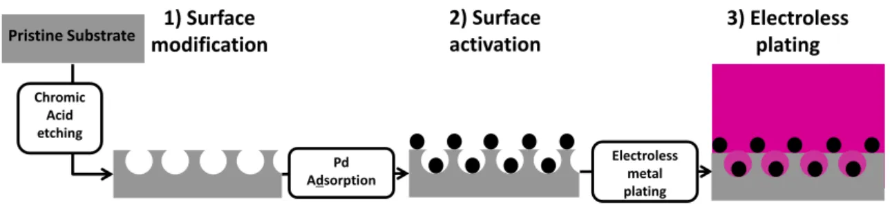
Contrary to gaseous and solid based metal deposition, for which the surface conditioning was directly followed by the metal deposition itself, common electroless processes involve three main steps: (i) surface conditioning (See section II.1), (ii) surface activation or surface seeding with a catalyst, (iii) electroless deposition itself, which is the chemical deposition of a metal film from a solution containing a mild reducing agent and a derivative of the metal to be plated onto the seeded substrate [6, 9] (Figure 6). As described in Mallory’s book [9], almost all metals of the Group VIII of the periodic table (Au, Pt, Ni, Cu, Co, Fe,…) can be plated and
exhibit autocatalytic behavior. Hence, the electroless metal deposition is not stopped once the catalyst is covered by the first metal deposit. All these active metals are also well-known as hydrogenation/dehydrogenation catalysts, which is a crucial point as explained later. Electroless deposition is actually a complex process involving multiple and simultaneous redox processes on the substrate surface which composition, structure and morphology are increasingly modified by the plating. Besides, mechanistic details of metal deposition still remain unclear. The mixed potential theory [9, 40] is the most used and experiment-based model for electroless metal deposition and consists of an initial spontaneous oxidation of the reducing agent at the catalytic surface, leading to electron charging of the substrate surface until its electrochemical potential becomes sufficiently negative to reduce the metallic derivative to metal. The mixed potential theory provides a correct description of the electroless plating mechanism when electron transfer between the reducing agent and the metallic ion is mediated by the activated surface and can be described by electrochemically controlled partial reaction currents [9, 40-42]. Further details on its mechanism will be given in the next parts.
Figure 6 : Common industrial electroless plating process divided in three main steps (Adapted from Ref. [43])
2.3.1. Electroless plating step: Electrochemical-based mechanism
The electroless deposition mechanism is complex and can be explained using fundamentals of electrochemical deposition rules. As shown in Figure 7a), an electrolytic cell for electrodeposition of metals from an aqueous solution needs, at least, to be composed of a power supply, two metal electrodes (metal cathode and metal anode) and water containing the dissolved ions of a metal salt MA (Mz+; Az-). The equivalent electrolytic cell for electroless metal deposition is shown in Figure 7b) and a comparison of both cells shows that in
Chromic Acid etching Pd Adsorption Electroless metal plating 2) Surface activation 3) Electroless plating 1) Surface modification Pristine Substrate
electroless deposition there is no power supply and the system has only “one metal electrode”.
As well as for electrodeposition solution, the electroless solution composition is very complex and contains at least the following components: water, a metal salt MA (Mz+; Az-), a reducing agent, pH buffer, bath stabilizers and complexing agents of the metal salt. Without any metal electrode, this solution remains stable such as in the case of the electrodeposition solution without any power applied.
Figure 7: a) Electrolytic cell for electrodeposition of metal, M, from an aqueous solution of metal salt, MA and b) Electrolytic cell for electroless deposition of metal M from an aqueous solution of metal
salt MA and a reducing agent Red.
The overall reactions of electrodeposition and electroless deposition may be used to compare these two processes. The process of electrodeposition of metal M is represented:
Msolutionz+ + ze− electrode Mlattice Eq. 1 Catalytic substrate Solution: H2O, M+, A-, Red, (complexing agent, (stabilizers,…) Red e-M+ e-Solution H2O M+, A -V Voltmeter A + -Metal anode Metal cathode Amperometer Power supply
a) Electrolytic cell for electrochemical
In this process z electrons are supplied by an external power supply. The overall reaction of electroless metal deposition is:
Msolutionz+ + Redsolution
catalytic surface
Mlattice + Oxsolution Eq. 2
Where Ox is the oxidation product of the reducing agent Red.
This reaction only occurs on the activated surface, also called catalytic surface and more specifically on appropriate metal previously adsorbed onto the surface such as Pd0 particles. The reducing agent Red in the solution is the electron source and gives electrons to the catalytic surface and metal ions Mz+ at the surface. The reaction represented by Eq. 2 must be conducted in such a way that a homogeneous reaction between Mz+ and Red, in the bulk of the solution, is inhibited. Indeed, in addition to the source of metal ion Mz+ and its reducing agent Red, the electroless plating solution also contains suitable complexing agents and stabilizers. All these components create a whole solution which is in a metastable state at a constant pH.
Concerning the complexing agents, they perform three main functions in the electroless plating solution [9]. First, they exert a buffering action that prevents the pH of the solution from increasing or decreasing too fast. Then, they prevent the formation of metal hydroxides and reduce the concentration of free metal ions, which avoid the spontaneous reduction in solution and the subsequently decomposition of the electroless plating bath. In addition to these functions, complexing agents also affect the deposition reaction and hence the resultant metal deposit [9]. Indeed, the rate of metal deposition is proportional to the rate at which the metal complexing agent dissociates to form “free” metal ion. Thus, the plating rate is inversely related to the complexing agent stability constant, i.e., the higher the complexing agent stability constant, the lower the rate of complexing agent dissociation and concomitantly, the lower the rate of deposition. Lastly, in some cases, the nature of the metal complexing agent and its stability constant also affect the composition of the metal deposit. This will be described in the next parts.
As a result of its complex composition, electroless plating bath are actually metastable mixtures, which may decompose spontaneously at any time [9]. Bath decomposition is usually preceded by an increase of the volume of hydrogen gas evolved and the appearance of a
finely-divided black precipitate throughout the bulk of the solution. This precipitate consists of metal particles. Fortunately, chemical agents called stabilizers (or catalytic inhibitors, or poisons of the catalytic growth) are present to prevent the homogeneous reaction that triggers the subsequent random decomposition of the entire plating bath. Plating bath decomposition can be virtually eliminated by the addition of only trace amounts of stabilizer to the electroless plating solution. As described in Mallory’s book, Gutzeit [9, 44-47] pointed out that most of these so-called "anti-catalysts" are identical to the materials that prevent hydrogenation/dehydrogenation catalysis.
Consequently, the chemical and physical properties of an electroless metal coating depend on its composition, which, in turn, depends on the formulation and operating conditions of the electroless metal plating bath.
As shown in Figure 7a), electrochemical deposition involves two electrodes, a cathode and an anode, which induce two separate electron-transfer reactions that occur at two spatially separated electrode-electrolyte interfaces. At the cathode a reduction reaction occurs and at the anode an oxidation reaction occurs: for example,
Mlattice anode
Msolution𝐳+ + 𝐳𝐞− Eq. 3
In electroless deposition the two electrochemical reactions, reduction of Msolutionz+ and oxidation of Redsolution, occur at the same electrode, at the same electrode–electrolyte interface (Eq. 3 and Figure 7b)). Thus, in electroless deposition there is a statistical division of the catalytic sites on the substrate into anodic and cathodic sites. Since these catalytic sites are part of the same piece of substrate, there is a flow of electrons between these sites [48].
In the following sections, the electrochemical model describing the electroless deposition mechanism will be discussed and coupled with the mechanistic approach.
Electrochemical model: Mixed-potential theory (MPT)
An electrochemical model for the electroless metal deposition was suggested by Paunovic and Saito on the basis of the Wagner–Traud mixed potential theory of corrosion processes
[49-51]. According to the mixed-potential theory (MPT) of electroless deposition, the overall reaction given by Eq. 2 can be decomposed into one reduction reaction, the cathodic partial reaction,
Msolutionz+ + ze−
catalytic surface
Mlattice Eq. 4
and one oxidation reaction, the anodic partial reaction,
Redsolution
catalytic surface
Oxsolution + me− Eq. 5
Thus, the overall reaction (Eq. 2) is the outcome of the combination of two different partial reactions (Eq. 4 and Eq 5). As mentioned above, these two partial reactions, however, occur at one electrode, the same metal–solution interphase. According to the electrochemistry laws, the equilibrium potential of the reducing agent, Eeq,Red (Eq. 5) must be more negative than that of the metal electrode, Eeq,M (Eq. 4), so that the reducing agent Red can function as an electron donor and Mz+ as an electron acceptor.
According to the mixed-potential theory, the overall reaction of the electroless deposition ;Eq. 2Ϳ can be described electrochemically in terms of current–potential curves thanks to the Evans diagram. In this method the sign of the current density is suppressed. Figure 8 shows a general Evans diagram with current–potential functions i = f(E) for the individual electrode processes, Eq. 4 and Eq. 5. According to this presentation of the mixed-potential theory, the current–potential curves for individual processes, ic = iM = f(E) and ia = iRed = f(E), intersect. The coordinates of this intersection have the following meaning:
- The abscissa, the current density of the intersection, is the deposition current density idep (i.e., log idep), that is, the rate of electroless deposition in terms of mA.cm-2;
-
Figure 8 : Evans diagram of current–potential curves for a system with two different simultaneous electrochemical reactions corresponding to Eq. 4 and Eq. 5 (Extracted from Ref. [48])
When the catalytic surface is introduced into an aqueous solution containing Mz+ ions and a reducing agent, the partial reduction reaction (Eq. 4) and the partial oxidation reaction (Eq.5) occur simultaneously. Each of these partial reactions strives to establish its own equilibrium, Eeq. The result of these processes is the creation of a steady state with a compromised potential called the steady-state mixed potential, Emp. Consequently the potential of the redox couple Red/Ox (Eq. 5) is raised anodically from the reversible value Eeq,Red (Figure 8), and the potential of the metal electrode M/Mz+ (Eq. 4) decreased cathodically from its reversible value, Eeq,M, down to the mixed potential, Emp (Figure 8). Thus, the basic four characteristics of the steady-state mixed potential are:
- Both redox systems are shifted from their own characteristic equilibrium potentials by the overpotential η:
ηM = Emp - Eeq,M Eq. 6
ηRed = Emp - Eeq,Red Eq. 7
- An electrochemical reaction occurs in each redox system since both reactions, Eq. 4 and Eq. 5, are shifted from their equilibrium by introduction of the mixed potential.
- The criterion for a steady state is that the rate of reduction of Mz+
, the cathodic current density iM, is equal to the rate of oxidation of the reducing agent Red, the anodic current density iRed:
iM,deposition = iM,Emp = iRed,Emp Eq. 8
since no current can flow in an isolated system.
- A system at the steady-state mixed potential is not in equilibrium since an overall reaction does occur; therefore the free energy change is not equal to zero which corresponds to a system that is not in thermodynamic equilibrium.
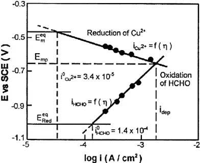
This mixed-potential theory has been verified by experimental studies for electroless deposition of copper. Indeed, Paunovic [51] reported that an electroless copper solution containing ethylenediaminetetraacetic acid (EDTA) as complexing agent for copper ions, formaldehyde as reducing agent, with pH = 12.5, and operated at 25oC, behaves in agreement with MPT. The polarization curves for reduction of copper ions and oxidation of formaldehyde are shown in Figure 9. The intersection potential for these curves was found to be similar to the value of the equilibrium potential, or open circuit, of a copper electrode undergoing electroless deposition in the complete solution. Similarly, the estimated copper deposition rate at Emp in Figure 9 (2.2 mg.h-1.cm-2) was close to the value measured gravimetrically for an electrolessly-plated substrate, 1.8 ± 0.2 mg.h-1cm-2.
Figure 9 : Current-potential curves for reduction of copper ions and oxidation of formaldehyde. “Eeq,M”
and “Eeq,Red” are the open circuit potentials for the copper ion reduction and formaldehyde oxidation
reactions, respectively. The vertical lines represent the exchange current densities for the two half reactions, and the deposition current density for the complete electroless solution (Extracted from
Ref. [48]).
Steady-state electroless metal deposition at mixed potential Emp is preceded by a non-steady-state period, called the induction period. The induction period is defined as the time necessary to reach the mixed potential Emp at which steady-state metal deposition occurs. It is determined in a simple experiment in which a piece of metal is immersed in a solution for electroless deposition of a metal and the potential of the metal is recorded from the time of immersion (or the time of addition of the reducing agent, i.e., time zero) until the steady-state mixed potential is established. A typical recorded curve for the electroless deposition of copper on a copper substrate using HCHO as reducing agent is shown in Figure 10. Paunovic studied this induction period for the overall process, dividing it into dependence of the open-circuit potential (OCP) on the oxidation and reduction partial reactions, that is, into individual induction periods for each partial process [52]. The OCP of the Cu/Cu2+ system is reached instantaneously. From a comparison of these OCP curves, it has been concluded that the rate of setting of the OCP of the reducing agent, HCOOH, was the rate-determining partial reaction in the setting of the steady-state mixed potential.
Figure 10 : Induction period for the solution containing EDTA (0.3 M), CuSO4 (0.05 M), formaldehyde
(2.5 g/L), Cu electrode, 25°C, pH=12.50, SCE reference electrode and argon atmosphere (Extracted from Ref. [52]).
The MPT has been tested and verified by experimental studies for other metals such as nickel or even gold associated with different reducing agents such formaldehyde or hypophosphite for electroless copper deposition [51, 53-56], dimethylamine borane for electroless nickel deposition [51] and potassium borohydride for electroless gold deposition [57].
The described MPT assumes that the two partial reactions are independent from each other, which is not always true. For example, Schoenberg [58] has shown that formaldehyde (used as reducing agent for electroless copper deposition) enters the first coordination sphere of the copper tartrate complex and thus influences the rate of the cathodic partial reaction. Ohno and Haruyama [59] showed the presence of interference in partial reactions for electroless deposition of Cu, Co, and Ni in terms of current–potential curves [57].
These latter details illustrate the complexity of electroless processes and the presence of a variety of factors that should be taken into account when applying the MPT to electroless processes. To better explain this electroless plating process, Mallory, Paunovic and Van Den Meerakker [9, 48, 60] described the mechanism of each (anodic and cathodic) partial reaction and the effects of all the variables of the electroless process; the next part will summarize that study:
Anodic partial reaction
The overall anodic partial reaction (Eq. 5), usually proceeds in at least two elementary steps (like the cathodic partial reaction): formation of electroactive species, and charge transfer. The formation of electroactive species (R) usually proceeds in two steps through an intermediate (Redinterm):
Red → Redinterm Eq. 9
Redinterm → R Eq. 10
Van den Meerakker [61, 62] proposed the following general mechanism for the formation of electroactive species R from the intermediate Rinterm, now represented by R-H:
Redinterm = R − H → Rads + Hads Eq. 11
Where Rads is the electroactive species R adsorbed at the catalytic surface. According to this mechanism which corresponds exactly to the dehydrogenation mechanism (Eq. 11), the electroactive species Rads is formed in the process of dissociative adsorption (dehydrogenation) of the intermediate R-H, which involves breaking the R-H bond.
The adsorbed hydrogen, Hads, may desorb in the chemical reaction
2 Hads → H2 Eq. 12
or in the electrochemical reaction
Hads → H++ e− Eq. 13
For example, in electroless deposition of copper, when the reducing agent is formaldehyde and the substrate is Cu, Hads desorbs in the chemical reaction (Eq. 12) [60]. If the substrate is Pd or Pt, hydrogen desorbs in the electrochemical reaction (Eq. 13) [60]. In electroless deposition of gold and silver, both electrochemical and chemical reactions are observed [60].
The most studied anodic partial reaction is the oxidation of formaldehyde, Red = HCOOH. The overall reaction of the electrochemical oxidation of formaldehyde at the copper electrode in an alkaline solution proceeds as
HCOH + 2OH− → HCOO−+ H
2O + 1 2H2+ e− Eq. 14
The mechanism of this reaction involves the following sequence of elementary steps [61-63]: 1. Formation of electroactive species R in three steps:
a. Hydrolysis of HCOOH and formation of methylene glycol:
HCHO + H2O ↔ H2C(OH)2 Eq. 15
b. Dissociation of methylene glycol:
H2C(OH)2+ OH− ↔ H2C OH O−+ H2O Eq. 16
c. Dissociative adsorption of the intermediate, H2C OH O− (R-H), involving breaking the C-H bond in the R-C-H molecule:
H2C OH O− ↔ [HC OH O−]ads + Hads Eq. 17
where [H2C OH O−]ads is Rads.
2. Charge transfer, the electrochemical oxidation (desorption) of electroactive species Rads:
[HC OH O−]ads + OH− → HCOO−+ H2O + e− Eq. 18
where HCOO− is the oxidation product of Rads(Ox).
Okinaka and Vandenmeerakker applied this kinetic scheme to other reducing agents, such as borohydride (Red = BH4-), hypophosphite (H2PO2-), and hydrazine (NH2NH2) where the electroactive species RH are [BH2OH-]ads, [HPO2-]ads, and [N2H3-]ads, respectively [57, 61]. It was shown that parallel reactions occur with some reducing agents. For example, in the case of
oxidation of BH4- and H2PO2-, the parallel reactions are probably cathodic reactions, resulting in incorporation of B and P into the metal deposit, respectively. These “codeposits” obviously modify the properties of the electroless metal layer. As an example, when electroless Ni is deposited from solutions containing BH4- as the reducing agent, a NiB layer is obtained and provides better diffusion barriers properties than usual Ni layer, whereas when the reducing agent is H2PO2-, a NiP layer is obtained and provides better corrosion resistance.
Therefore, as introduced earlier, in that particular cases of BH4- and H2PO2- reducing agents, the nature of the metal complexing agent and its stability constant also affect the composition of the metal deposit. As an example for NiP deposit, when the fraction of catalytic sites onto which nickel ions have been adsorbed is large (small complex stability constant), the number of sites available for phosphorus reduction is small and the phosphorus content of the deposit is lowered. On the other hand, when the stability constant is relatively large, the free nickel ion concentration is low, and the fraction of sites covered by adsorbed nickel is small; hence, in the latter case, the number of sites available for phosphorus reduction is large and the phosphorus content of the coating is increased.
Finally, from the kinetic aspects, the major factors determining the rate of the anodic partial reaction are pH and additives. Since OH- ions are reactants in the charge-transfer step (e.g., Eq. 18) the effect of pH is direct and significant [64]. Additives may have an inhibiting or an accelerating effect.
Cathodic partial reaction
Generally, metal ions in a solution for electroless metal deposition have to be complexed with a ligand. As previously explained, complexing agents are necessary to prevent formation of metal hydroxide, such as Cu(OH)2, in electroless copper deposition. One of the fundamental problems in electrochemical deposition of metals from complexed ions is the presence of electroactive (charged) species. The electroactive species are in most cases, partially complexed metal ions and the kinetic scheme is that of charge transfer is preceded by partial or total dissociation of the complex.
The mechanism of the second case involves a sequence of at least two basic elementary steps:
- Formation of electroactive species followed by the charge transfer from the catalytic surface to the electroactive species. Electroactive species Mz+ are formed in the first step by dissociation of the complex [MLx]z+xp:
[MLx]z+xp → Mz++ xLp Eq. 19
where p is the charge state of the ligand L, z is the charge of the non-complexed metal ion, and z+xp is the charge of the complexed metal ion.
- The charge transfer
Mz++ ze− → M Eq. 20
proceeds in steps, usually with the first charge transfer (one-electron transfer) serving as the rate-determining step (RDS):
Mz++ e− RDS Mlattice Eq.21
Thus, from the kinetic aspects, the cathodic partial reaction is an electrochemical reaction (Eq. 20) that is preceded by a chemical reaction (Eq. 21). Paunovic demonstrated that the major factors determining the rate of the partial cathodic reaction are concentrations of metal ions and ligands, pH of the solution, and type and concentration of additives [52]. These factors determine the kinetics of partial cathodic reaction in a general way, as given by the fundamental electrochemical kinetic equations [48]. Therefore, Schoenberg, Paunovic and Arndt [58, 65-67] have shown that additives may have two opposing effects: acceleration and inhibition such as in the case of the anodic partial reaction.
Overall mechanism and alternative models
As mentioned earlier, the overall mechanism of the electroless deposition is governed by the electrochemical rules and more particularly the mixed potential theory. However, this theory has to be associated with the mechanistic approach of the reduction of metal salt and the oxidation of a reducing agent onto a metal electrode which are governed by the
heterogeneous catalysis rules. A scheme of the electroless mechanism describing the main steps of the process is suggested in Figure 11.
As suggested in Figure 11, in a first part, the reducing agent is adsorbed onto the metal surface leading to its R-H homolytic cleavage. In a second part, at this solid/solution interface, the coordination sphere of the complex salts is at least partially modified by a ligand adsorption onto the catalyst. This partial metal complex dissociation allows afterward obtaining the electron transfer between the adsorbed species of the reducing agent and the metal salt leading to its reduction onto the metal surface. Depending on the catalyst nature and the reactive baths, either the red or the blue pathway is promoted (Figure 11). Then, this process being autocatalytic, this mechanism is repeated as long as the activated surface is immersed into the electroless plating bath. It has to be said that for convenience reasons, the suggested mechanism in Figure 11 does not describe the reduction of the reducing agent itself that occurs in the case of Boron or Phosphorous-containing reducing agents.
This chemical mechanism associated with the mixed potential theory finally provides a correct description of the electroless plating mechanism when electron transfer between the reducing agent and the metallic ion is mediated by the activated surface and can be described by electrochemically controlled partial reaction currents [9, 40-42]. Nevertheless, the mixed potential theory is not valid when an electron transfer can directly occur between the reducing agent and the metallic ion contained in the electroless plating bath, which is usually prevented by using stabilizers. More recently, improved electroless deposition models of the different mechanistic steps were published trying to take all the components of the electroless plating bath into account. At this stage, there are only based on theoretical calculations without any experimental data to confirm those models [68-71].
Figure 11 : Scheme of the electroless mechanism
2.3.2. Surface activation step through Pd-Sn catalyst
As previously introduced, electroless deposition starts only on a catalytic surface commonly based on Pd species. Indeed, this surface activation consists in the adsorption of a catalyst of the electroless plating growth onto the polymer surface. Palladium, in its zero oxidation state, is a “universal” catalyst used to initiate most electroless reactions involving various autocatalytic metals so that it plays a fundamental role in any electroless process [9]. The deposition of palladium seeds on the polymer surface is enough to initiate the redox reaction. The reaction goes further thanks to the autocatalytic property of the deposited metal species which is based on the capability of these metals to reduce their own ions, hence the term “autocatalytic” also used to describe the electroless plating process.
Historically, this seed layer was deposited by a two-step process consisting of substrate treatment by the successive immersion in stannous chloride (SnCl2) and palladium chloride (PdCl2) aqueous solutions [72-75]. The tin bath treatment is named "sensitization" and the palladium (or similar) second treatment is called "activation". The sensitization consists in the adsorption of Sn2+ ions onto the pretreated surface, followed by the activation which leads to the reduction of Pd ions by the adsorbed Sn2+ ions, according to Eq. 22:
𝐒𝐧𝟐++ 𝐏𝐝𝟐+ → 𝐒𝐧𝟒++ 𝐏𝐝𝟎 Eq. 22
This two-step process was given up between 1975 and 1980 in favor of a one-step process using a mixed SnCl2-PdCl2 solution [5, 74, 76-78] with core-shell Pd-Sn colloidal species which exhibit complex compositions and chemistries [75]. As suggested by other groups [79], Cohen and West have shown by Mössbauer spectroscopy [75, 80] that Pd/Sn solutions consist of nano-colloids of around 2 nm. Indeed, Mössbauer spectroscopy gives access to chemical information, like the oxidation state of Pd and Sn, averaged over the whole ensemble of colloids in suspension. This work led to a discussion about the nature of the activator solution in the literature [81, 82]. The nano-colloids comprise a Pd-rich, zerovalent and crystalline Pd-Sn alloy, which functions as the catalytically component for electroless deposition [83-86]. Pd-Sn nano-colloids are surrounded by a stannic shell consisting primarily of µ-hydroxy-bridged SnII and SnIV which chemical composition and thickness depend on the working conditions (pH, solution composition, temperature, oxygen exposure) [77, 87, 88]. Before the electroless plating step, an acid “acceleration” treatment that dissolves a portion of the stannic shell to expose the catalytically active Pd-Sn core to the electroless plating is required. The adhesive properties of the stannic shell are obviously critically important for using the Pd-Sn colloid as an electroless catalyst. However, the stannic shell adsorption is only based on Van der Walls and other non-covalent interactions and generally leads to poor adhesion. Even if the adhesion of those Pd-Sn colloids is reinforced by the surface treatment, the use of covalent rather than non-covalent interactions to adhere the catalytic Pd core to the surface to be plated represent a straightforward and attractive means to enhance the electrolessly deposited metal layer adhesion.
2.3.3. Conclusions
Once the surface is activated by Pd0 surface adsorption, different kinds of metal can be electrolessly deposited by immersion in the electroless plating bath and as previously explained, almost all the metals of the Group VIII of the periodic table (Au, Pd, Ni, Cu, Co,…) can be plated and exhibit autocatalytic behavior. In all cases, the electroless plating bath will be composed by a ionic complex of the metal to be plated, a reducing agent, a stabilizer which prevents spontaneous reduction in solution [9], but may delay or even hinder the initiation of the autocatalytic reaction through a kind of poisoning of the catalytic sites, hence resulting in an increase in the activation energy of the reaction [9]. Hence, the working conditions of the electroless plating bath, such as pH and temperature, are often controlled in situ on industrial setups. It is noteworthy that according to the plating bath composition, it is possible to induce different metal layer properties; for example, the incorporation of P or B into the metal layer respectively induces better corrosion resistance or better diffusion barriers layers than pure metal.
For most of the metal plated polymers, this wet process is the most efficient one and consequently the most used one by the polymers electroless plating industry. Accordingly, they are still industrial challenges to take up such as the replacement of the Pd-Sn activation step which involves weak interactions with substrates, and generates toxic waste due to the use of hazardous tin species and important costs in waste management.
In addition, the ability to develop a projection or transfer-based process instead of the described wet process involving many baths would ideally match the current industrial demands: Only the required matter would be used which consequently could minimize the waste production and would induce cost savings.
Lastly, a projection or transfer-based process would also enable the localization of the metal deposition and could be used for the fabrication of metal patterns for electronic applications.
2.4. Alternative method: Jet-Metal™ technology
Recently, an alternative to the wet and dried based metallization processes, combining spray deposition and electroless plating process has been proposed by the Jet Metal™company [89]. As shown in Figure 12, metallization is obtained by spraying two solutions, at room