HAL Id: tel-01299794
https://pastel.archives-ouvertes.fr/tel-01299794
Submitted on 8 Apr 2016HAL is a multi-disciplinary open access
archive for the deposit and dissemination of sci-entific research documents, whether they are pub-lished or not. The documents may come from teaching and research institutions in France or abroad, or from public or private research centers.
L’archive ouverte pluridisciplinaire HAL, est destinée au dépôt et à la diffusion de documents scientifiques de niveau recherche, publiés ou non, émanant des établissements d’enseignement et de recherche français ou étrangers, des laboratoires publics ou privés.
Polypropylene : Process, Microstructure and Properties
Ahmed Abdennadher
To cite this version:
Ahmed Abdennadher. Injection Moulding of Natural Fibre Reinforced Polypropylene : Process, Mi-crostructure and Properties. Other. Ecole Nationale Supérieure des Mines de Paris, 2015. English. �NNT : 2015ENMP0045�. �tel-01299794�
MINES ParisTech CEMEF-UMR CNRS 7635
Rue Claude Daunesse CS 10207 - 06904 Sophia Antipolis Cedex, France
T
H
E
S
E
École doctorale n° 364 : Sciences Fondamentales et Appliquées
présentée et soutenue publiquement par
Ahmed ABDENNADHER
le 01 Décembre 2015
Injection Moulding of Natural Fibre Reinforced-Polypropylene:
Process, Microstructure and Properties
Injection de Polypropylène Renforcé de Fibres Naturelles:
Procédé, Microstructure et Propriétés
dla thèse
Doctorat ParisTech
T H È S E
pour obtenir le grade de docteur délivré par
l’École nationale supérieure des mines de Paris
Spécialité « Mécanique Numérique et Matériaux»
Directrice de thèse : Tatiana BUDTOVA Directeur de thèse : Michel VINCENT
Jury
Mme Anne BERGERET, Professeur, C2MA, Mines d’Alès Rapporteur
M. Gilles AUSIAS, Maître de conférences, LIMATB, Université de Bretagne-Sud, Lorient Rapporteur
M. Jörg MÜSSIG, Professeur, Université de sciences appliquées de Brème- Allemagne Examinateur
M. Johnny BEAUGRAND, Maître de recherche, INRA, Université de Reims Champagne Ardenne Examinateur
M. Jean-Jacques FLAT, Docteur, Arkema, CERDATO, Serquigny Examinateur
M. Michel VINCENT, Directeur de recherche, CEMEF, Mines ParisTech, Sophia Antipolis Examinateur
Acknowledgements
Firstly, I would like to express my gratitude to my supervisors, Dr. Tatiana Budtova and Dr. Michel Vincent for their continuous support throughout my PhD project and their assistance in the manuscript writing. I appreciate their expertise, understanding and patience.
Special thanks go to the rest of the committee, Prof. Anne Bergeret, Dr. Gilles Ausias, Prof. Jörg Müssig, Dr. Johnny Beaugrand and Dr. Jean-Jacques Flat, for letting my defence be an enjoyable moment and for their comments and suggestions.
This work was performed within the Industrial Chair in Bioplastics supported by MINES ParisTech and Arkema, L’Oréal, Nestlé, PSA and Schneider Electric. I am grateful to all the members of this Chair for the collaboration that they had shown to make my thesis successful.
I would like also to thank all the members of the Centre for Materials Forming (Cemef) for their friendship and useful suggestions. I thank in particular Sabri Khalfallah involved as a trainee in this project for helping in experiments. I am also thankful to Prof. Jean-Marc Haudin, Dr. Edith Peuvrel-Disdier and Prof. Bruno Vergnes for their sound advices in all stages of this research. I am grateful to Thierry Collin for his technical support and to Marie-Francoise Guenegan for her administrative support. Deep thanks go to Dr. Rudy Valette for his precious advices on research as well as on my career. I must also thank Dr. Olivia Levingston and Dr. Sian Jones for their English courses. They incited me to write my thesis in English.
I acknowledge my gratitude to people of “Centre des Matériaux at Ecole des Mines d’Ales” for the absolute support to the thesis. Special thanks to Benjamin Gallard for helping in experiments and Nicolas LeMoigne for his advices.
I am grateful also to Dr. Mohamed Jaziri from the National School of Engineers of Sfax for his support and advices before and during my thesis.
Finally, special thanks to my family. Words cannot express how grateful I am to my parents for all the sacrifices that they have made on my behalf. Deep thanks to my brother, my sister-in-law and my niece for supporting me and for attending my defence.
Table of Contents
Articles & Communications ... 1
Extended abstract of the thesis in French ... 3
Chapter 1 General Introduction ... 15
Chapter 2 Materials & Methods ... 23
1. Materials ... 24
1.1. Polypropylene ... 24
1.2. Fibres ... 24
2. Processing: compounding and injection moulding ... 26
2.1. Compounding ... 26
2.2. Injection moulding ... 29
3. Characterisation ... 33
3.1. Fibre size analysis ... 33
3.2. Microstructure analysis ... 36
3.3. Rheology of molten composites ... 38
3.4. Mechanical properties of composites ... 43
3.5. Observation of composites morphology by Scanning Electron Microscopy (SEM) 46 4. References ... 47
Chapter 3 Fibre size analysis during processing ... 49
1. The state of the art ... 50
1.1. Glass fibre reinforced thermoplastic ... 50
1.3. Conclusion ... 58
2. Results and discussions ... 59
2.1. Glass fibres ... 59
2.2. Tencel ... 62
2.3. Flax ... 64
2.4. Comparison between fibre types ... 70
2.5. Conclusions ... 74
3. References ... 75
Chapter 4 Fibre orientation and dispersion in injection-moulded parts ... 79
1. State of the art ... 80
1.1. Characterization techniques and approaches in fibre orientation characterisation ... 80
1.2. Fibre orientation results ... 88
1.3. Conclusions ... 101
2. Results and discussion ... 103
2.1. Qualitative observations ... 103
2.2. Distribution of fibre concentration throughout the thickness ... 114
2.3. Distribution of fibre orientation throughout the thickness ... 117
2.4. Fibre bending ... 124
2.5. Conclusions ... 126
3. References ... 128
Chapter 5 Rheological properties of composites ... 135
1. State of the art ... 136
1.1. Dynamic rheology ... 136
1.2. Capillary rheology and comparison with dynamic ... 144
1.3. Conclusions ... 147
2.1. Dynamic rheology results ... 148
2.2. Capillary rheology and comparison with dynamic ... 158
2.3. Conclusions ... 165
3. References ... 167
Chapter 6 Mechanical properties of composites ... 173
1. State of the art ... 174
1.1. Tensile properties ... 174
1.2. Impact properties ... 181
1.3. Conclusions ... 184
2. Results and discussion ... 185
2.1. Tensile Properties ... 185
2.2. Impact properties ... 199
2.3. Conclusions ... 205
3. References ... 207
Chapter 7 Pressure and fibre orientation simulation: comparison to
experiments ... 213
1. State of the art ... 214
1.1. Pressure in the mould cavity ... 214
1.2. Computation of injection moulding ... 214
1.3. Experimental pressure and comparison with simulation ... 215
1.4. Prediction of fibre orientation ... 221
1.5. Examples of simulation and comparison with experiment ... 224
1.6. Conclusions ... 228
2. Results and discussions ... 230
2.1. Experimental Pressures ... 230
2.3. Conclusions ... 254
3. References ... 256
General conclusions and prospects ... 262
1. Conclusions ... 262
Articles & Communications
1
Articles & Communications
This work has led to an article that is published in an international journal and three others are under progress. Several communications (oral presentations and posters) were given in national and international conferences.
Articles
Abdennadher, A., Vincent, M. and Budtova, T, “Rheological properties of molten flax- and Tencel®-polypropylene composites: Influence of fibre morphology and concentration J. Rheol. 60, 191 (2016)
Oral presentations
Abdennadher, A., Vincent M. and Budtova T., Microstructure of injected natural fibre reinforced propylene, “Matériaux” conference, Montpellier, France (November 2014)
Abdennadher, A., Vincent M. and Budtova T., Microstructure of injected natural fiber-polymer composite, American Society for Composites, 29th Technical Conference and 16th US-Japan Conference on Composite Materials, San Diego, USA, September (2014)
Abdennadher, A., Budtova T. and Vincent M., «Rheological properties of flax and Tencel® fiber reinforced polypropylene, Polymer Processing Society conference, Cleveland, USA (June 2014)
Abdennadher, A., Budtova T. and Vincent M., Rheological properties of molten natural fibre-polymer composite: cases of flax and Tencel®, 3rd EPNOE Conference Nice, France (October 2013)
Abdennadher, A, Vincent M., Budtova T., Rheological properties of molten natural fiber-polymer composite: Cases of flax and Tencel®, 41st JEPO conference, Aussois, France (September 2013)
Articles & Communications
2
Posters
Abdennadher, A.,Vincent M. and Budtova T., Microstructure of injected natural fiber-reinforced polypropylene, Natural fibres composite Workshop, Sophia-Antipolis, France (February 2015)
Abdennadher, A., Vincent M. and Budtova T., Rheological properties of molten natural fibre-polymer composite: Cases of flax and Tencel®, Mecamat conference, Aussois, France (January 2014)
Extended abstract of the thesis in French
3
Extended abstract of the thesis
in French
Résumé étendu de la thèse
Introduction générale
Le réchauffement climatique et l’ampleur de l’effet des déchets non-biodégradables sur l’environnement sont devenus des problématiques d’actualité sur lesquelles les industriels se sont penchés. Cela a généré la mise en place de stratégies de développement durable qui encouragent à chercher une alternative aux matériaux fossiles à la fois respectueuse de l’environnement et garante de performances similaires.
Dans ce contexte, les fibres naturelles ont reçues une grande attention au cours des deux dernières décennies pour remplacer les fibres de verre comme renfort dans les composites polymères. En plus de leur aspect écologique, les principales raisons qui incitent à l’utilisation des fibres naturelles dans les composites sont leur faible coût et le gain en poids toute en gardant des propriétés mécaniques similaires aux composites à fibres de verre. La faible densité des fibres naturelles attire particulièrement le secteur des transports (automobile, ferroviaire, aéronautique…) très sensible à la réduction de poids. Les composites à fibres naturelles sont utilisés dans les automobiles pour des pièces intérieures comme des revêtements, des garnitures de tableaux de bord, des panneaux de porte... D'autres secteurs d’application des composites à fibres naturelles sont apparus comme le sport et loisirs (ski, snowboard, vélo...) grâce à leurs bonnes propriétés d'amortissement, les instruments de musique et haut-parleurs en raison de leurs excellentes performances acoustiques, ou aussi l’ameublement (bureau, chaise...) en raison de leurs aspect lorsque les fibres sont mélangés avec une matrice translucide.
Extended abstract of the thesis in French
4 Les fibres naturelles techniques utilisées comme renfort des polymères sont soit des fibres ligno-cellulosiques, provenant de tiges de plantes comme les lin, chanvre, jute et kenaf ou de graines (coton) ou de feuilles (sisal), soit des fibres à 100 % cellulosiques filées telles que les fibres Tencel (procédé Lyocell) ou viscose. Dans ce travail, deux types de fibres naturelles ont été utilisés, le lin et Tencel avec une matrice polypropylène, avec pour objectif :
d'étudier et de comprendre l'influence des différentes compositions et morphologies de fibres :
o sur la microstructure des composites, c’est à dire la taille, l’orientation et la concentration de fibres,
o sur les propriétés rhéologiques et mécaniques qui en résultent,
de vérifier si les modèles développés pour les fibres de verre peuvent prédire la pression pendant le remplissage de moule en injection et l'orientation des fibres naturelles dans des pièces moulées.
Les fibres de lin et Tencel sont différentes. Les composants principaux du lin sont la cellulose (64-81 %), l’hémicellulose (11-17 %), la lignine (2-3 %) et la pectine (2 %) tandis que Tencel est basée sur de la cellulose pure. De plus, elles présentent une morphologie différente. Tencel est une fibre élémentaire mince et flexible avec un diamètre uniforme (dû au procédé de filage), tandis que le lin est un «mélange» de fibres élémentaires semi-rigides minces et de faisceaux épais et rigides composés de fibres élémentaires assemblées. Enfin, leurs propriétés mécaniques intrinsèques sont également différentes. Il est donc supposé que ces différences de propriétés des fibres auront une influence sur la microstructure et les propriétés des composites.
En France, le lin de haute qualité est aujourd'hui cultivé dans les régions du nord (Normandie, Picardie et Nord-Pas-de-Calais) en raison des conditions climatiques modérées et du savoir-faire des liniculteurs. Avant d'être en mesure de renforcer un polymère, les fibres de lin sont soumises à un long cycle d'extraction comprenant le rouissage, la rupture, le teillage et le peignage. Plus de 80 % de la production de lin est aujourd'hui tournée vers l'industrie textile qui est leur application historique et seulement 10 % sont dédiés à un usage technique.
Le principal producteur de fibres de Tencel est la société autrichienne Lenzing qui nous a les aimablement fournies. La cellulose de base des fibres Tencel est extraite de la pulpe
Extended abstract of the thesis in French
5 principalement trouvée dans les eucalyptus. La cellulose est dissoute dans du N-méthylmorpholine-N-oxyde monohydrate, puis filtrée, centrifugée, filée, coagulée et séchée. En plus de leur utilisation principale dans l'industrie textile, les fibres Tencel sont couramment employées pour la fabrication de cordes ou des filtres automobiles.
Nous nous intéressons dans ce travail au polypropylène renforcé de fibres discontinues de lin et Tencel. Le mélange fibre/matrice se fait par extrusion bivis pour produire des granulés, qui sont ensuite transformés par injection. D’autres façons de fabriquer des composites thermoplastiques existent comme, par exemple, le moulage par compression. L’injection reste la méthode préférée pour fabriquer des pièces de géométries complexes avec une haute cadence et un faible coût de production. Le marché du moulage par injection est en pleine croissance avec l'augmentation des domaines d'application pour les composites à fibres naturelles. Le potentiel de ces matériaux combiné à la productivité du procédé d’injection satisfait au défi environnemental et à la performance industrielle. Toutefois, en raison de la complexité de choix et de la variété des fibres naturelles plusieurs questions subsistent.
Dans ce contexte, cette thèse a été lancée en octobre 2012 au Centre de Mise en Forme de Matériaux (Cemef) de Mines ParisTech, dans le cadre de la Chaire Industrielle Bioplastiques. Cette chaire est cofinancée par Mines ParisTech et cinq entreprises: Arkema, L'Oréal, Nestlé, PSA Peugeot Citroën et Schneider Electric. C’est un grand projet de recherche de 7 ans qui comprend différents thèmes dont l’objectif est de soutenir le développement et les applications de divers matériaux bio-sourcés (bioplastiques, matériaux ligno-cellulosiques et composites polymères à fibres naturelles). Une précédente thèse s’est déroulée dans le cadre de cette chaire portant sur le comportement et la rupture de fibres cellulosiques lors de leur compoundage avec une matrice polymère. La présente thèse vient compléter ce travail et se concentre sur l'étude et la compréhension des propriétés d’un polypropylène renforcé de fibres naturelles en abordant certaines questions autours du moulage par injection.
Problématiques
Les polymères renforcés de fibres de verre discontinues ont été largement étudiés et optimisés. La question principale ici est de savoir si les résultats et approches peuvent être étendus aux fibres naturelles. Les fibres de verre sont rigides, de diamètre constant et de propriétés uniformes. Comme mentionné ci-dessus, les fibres de lin techniques sont un
Extended abstract of the thesis in French
6 mélange de fibres élémentaires et de faisceaux. Pendant la mise en œuvre, les faisceaux se dissocient en faisceaux plus minces voire même en fibres élémentaires. En fonction de leur diamètre et longueur, les fibres de lin peuvent se présenter comme semi-rigides ou rigides. En outre, les fibres de lin sont un produit d’agriculture dont les propriétés varient avec les conditions de culture et d'extraction et la variété dont elles proviennent. Tout cela fait que leur morphologie est très différente de celle des fibres de verre. L'autre type de fibres de cellulose utilisée dans ce travail est Tencel. Ces fibres sont filées à partir d’une solution de cellulose, et donc leur morphologie, composition et propriétés sont bien contrôlées. Cependant, leur morphologie est très différente non seulement du verre mais aussi du lin. La principale différence avec des fibres de verre est que les fibres Tencel sont très flexibles, ce qui, a priori, ne permet pas d’adopter les approches développées pour des fibres de verre. Considérant tout cela, les points suivants seront précisés :
1) L'effet du procédé sur les fibres naturelles (rupture, dissociation en faisceaux) est crucial pour la compréhension de la microstructure au sein des pièces moulées par injection. Quelle différence d’endommagement entre lin, Tencel et verre va en avoir lieu pendant la mise en œuvre ? Quelle est l’ampleur de la casse des fibres pendant l'injection ? Quel est l’effet de la concentration sur la rupture des fibres ?
2) Les propriétés rhéologiques des polymères thermoplastiques renforcés de fibres naturelles à l’état fondu sont très importantes pour la simulation du procédé d’injection. Ces propriétés sont assez bien connues pour les composites à fibres de verre. Le comportement rhéologique des composites à fibres naturelles est-il similaire à celui des fibres de verre ? Quelle est l'influence du type de fibre et de leur flexibilité sur les propriétés viscoélastiques du composite à l’état fondu ?
3) Etant donné que la morphologie des fibres naturelles est différente de celle des fibres de verre, l'extrapolation aux fibres naturelles des méthodes utilisées pour caractériser la microstructure des composites à fibres de verre semble être discutable. Si elle s’avère impossible, une nouvelle méthode pour l'analyse de la distribution et de l'orientation des fibres doit être développée.
Extended abstract of the thesis in French
7 4) Comme les propriétés mécaniques des composites sont en corrélation directe avec la microstructure, les relations microstructure-propriétés devraient être étudiées pour la compréhension et pour l'amélioration des performances.
5) Dans le but d'optimiser les conditions d’injection pour les composites à fibres naturelles, il est essentiel de vérifier si les modèles d'orientation des fibres et de simulation du procédé existantes pour les thermoplastiques renforcés de fibres de verre sont adaptés aux polymères renforcés de fibres naturelles.
Pour répondre à ces questions, après l’introduction générale (Chapitre 1), la thèse se compose des parties suivantes :
Chapitre 2, qui décrit les matériaux et les méthodes utilisés dans cette étude
Chapitre 3, où la distribution de taille des fibres est analysée,
Chapitre 4, où la microstructure (orientation, concentration, courbures) des fibres est analysée
Chapitre 5, où le comportement rhéologique est mesuré
Chapitre 6, consacré au comportement mécanique
Chapitre 7, sur l’analyse et la simulation du procédé d’injection
Dans la suite nous allons présenter l’objectif de chaque chapitre et les principaux résultats trouvés.
Chapitre 2 : Matériaux et méthodes
Ce chapitre décrit les matériaux utilisés dans ce travail ainsi que les méthodes de préparation et de caractérisation de composites. Bien que ce travail concerne principalement les polymères thermoplastiques renforcés de fibres naturelles, l’étude est étendue aux fibres de verre pour comparaison. A titre de référence, le polypropylène pur a été également étudié.
Dans la première partie de ce chapitre, les informations sur tous les matériaux utilisés dans la présente étude ont été détaillées. Ensuite, les deux étapes de mise en forme, l’extrusion bivis et l’injection, ont été présentées. Les techniques expérimentales utilisées pour évaluer la microstructure des composites (microscopie optique et électronique), leurs propriétés
Extended abstract of the thesis in French
8 rhéologiques (en mode dynamique et capillaire) et leurs performances mécaniques (en tension et choc) ont été également décrites.
Chapitre 3 : Analyse de taille de fibres
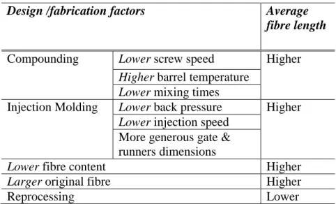
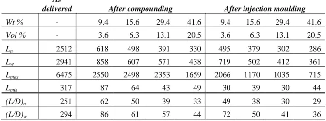
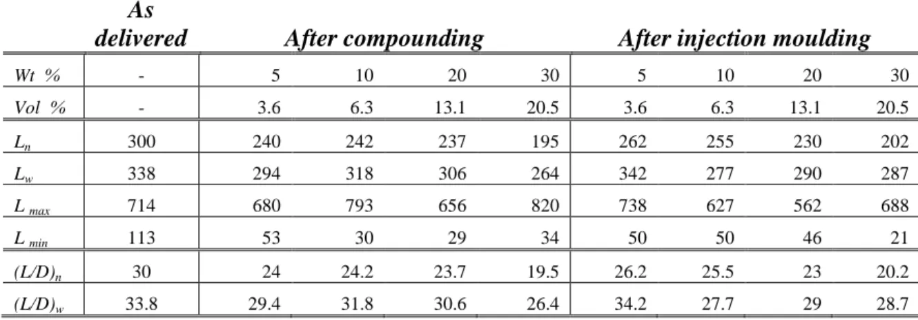
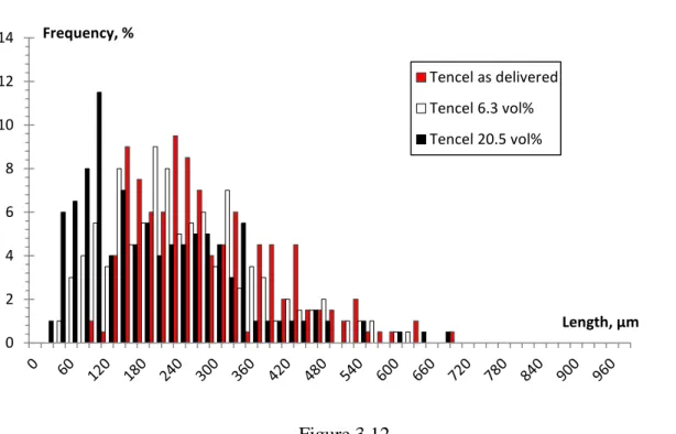
Les fibres de lin, Tencel et de verre ont été mélangées avec le polypropylène par extrusion bivis en plusieurs concentrations. Les différents composites ont été injectés dans un moule en forme de boîte. La distribution de tailles des fibres a été analysée après mélange et après injection, par dissolution du polypropylène et analyse par microscopie optique, cartographie et analyse d’images. Les fibres de verre ont été fortement cassées pendant le mélange et relativement peu endommagées lors du moulage par injection. La réduction de longueur est nettement moindre pour les fibres Tencel®. Les fibres de lin voient leur longueur et leur diamètre réduits au cours des deux étapes, les faisceaux étant dissociés. Le rapport de forme est donc constant. Quel que soit le type de fibres, la casse est plus importante lorsque la concentration augmente.
Chapitre 4 : Orientation et dispersion des fibres dans des pièces injectées
La complexité de la morphologie des fibres de lin et Tencel a nécessité une nouvelle approche de caractérisation permettant la quantification de leur orientation, distribution et courbure. Des surfaces de coupes parallèles au plan de la boite ont été obtenues par polissage pour plusieurs niveaux dans l’épaisseur. Des images de ces sections ont été ensuite prises par microscopie optique en mode réflexion et analysées par un logiciel de traitement d’image semi automatiquement.
En fonction de leurs formes apparentes, les fibres ont été classées en quatre catégories: droites, en forme de C, en forme de S et particules ou fibres hors-plan. Nous avons démontré qu'à cause de la différence de flexibilité, les fibres Tencel peuvent se courber en deux conformations: en forme de C ou en forme de S, tandis que les fibres de lin élémentaires se courbent seulement en forme de C.
Les fibres sont généralement alignées dans la direction d’écoulement à la surface de boite et perpendiculairement à cette direction dans le plan médian. Le nombre de fibres Tencel est trois fois plus grand que celui de lin pour la même concentration en volume. Cela a été
Extended abstract of the thesis in French
9 expliqué par la présence de faisceaux dans le lin qui persistent et n’arrivaient pas à se dissocier après l’injection. En outre, comme pour les fibres de verre, la concentration de lin augmente de la surface au plan milieu dans l’épaisseur, alors que la concentration Tencel est pratiquement indépendante de l'épaisseur.
Chapitre 5 : Propriétés rhéologiques des composites
Les propriétés des différents polypropylènes renforcés ont été étudiées en géométrie plan-plan en mode dynamique et en rhéométrie capillaire, pour des concentrations en fibres de 0 à 30 % en poids et des températures comprises entre 180 et 200 °C. Les mesures rhéologiques dynamiques ont montré que l'augmentation de la teneur en fibres et de la flexibilité de fibres (cas de Tencel) conduit à l’augmentation de la viscosité complexe et des modules élastique et visqueux. Une contrainte seuil apparente a été identifiée à basses fréquences lorsque la concentration volumique de fibres atteint le régime concentré. Cela est dû aux interactions entre fibres qui sont encore plus marquées lorsque la flexibilité de la fibre augmente. Pour la même concentration, les composites à fibres Tencel présentent une viscosité et une contrainte seuil apparente modérément plus élevées que celles des composites de verre et largement supérieures à celles du lin. Ceci est dû à la haute flexibilité et au plus grand nombre des fibres Tencel.
L'influence de la température sur la viscosité des composites a été analysée en utilisant la loi d'Arrhenius permettant le calcul de l'énergie d'activation. Pour les trois types de composites, l’énergie d’activation augmente quand la teneur en fibres augmente. L’ajout de fibres au polypropylène semble augmenter la "résistance" du composite à s’écouler. Les composites Tencel présentent une énergie d'activation plus élevée par rapport à celle du lin et du verre. Nous suggérons que des restrictions supplémentaires aux mouvements de chaînes de polymères peuvent être causées par la structure en réseau de fibres extrêmement flexibles.
La superposition rhéologie capillaire/dynamique obéit à la loi de Cox-Merz. Les courbes maitresses comprenant les mesures en dynamique et capillaire ont été modélisées par l’équation de Carreau-Yasuda à seuil. Le résultat obtenu donne l'évolution de la viscosité pour une large gamme de taux de cisaillement. Ce sera une donnée d’entrée importante pour le calcul numérique de la pression et de l'orientation des fibres (Chapitre 7).
Extended abstract of the thesis in French
10
Chapitre 6 : Propriétés mécaniques des composites
L'influence de la microstructure sur les propriétés en traction des composites a été étudiée dans des éprouvettes prélevées dans les boites injectées, à différents angles par rapport à la direction principale d'écoulement. Les échantillons alignés avec cette direction présentent de meilleures propriétés en traction que ceux orientés à 45 ° et 90 ° pour tous les composites étudiés. Les composites à base de verre présentent un module d’Young et une résistance à la traction supérieurs aux composites à fibres de lin et de Tencel, et ce quel que soit la concentration en fibres. Les composites Tencel montrent un plus grand allongement à la rupture par rapport aux composites de verre et de lin.
Les modèles de Cox-Krenchel et Kelly-Tyson ont été utilisés pour analyser la rigidité et la résistance à la traction, en utilisant des facteurs d'orientation améliorés et déterminés à partir des observations au Chapitre 4. Certains écarts se sont produits au niveau de la prédiction des propriétés de traction dans la direction principale d'écoulement. Ces écarts ont été associés à l'imprécision des valeurs de module de la fibre, à l'orientation des fibres hors plan, aux courbures des fibres et à la possibilité de présence d’une couche appauvrie en fibres vers la surface.
L'investigation des propriétés d'impact des composites sur des éprouvettes séparément injectées a montré que les composites à fibres Tencel ont la résistance à l'impact la plus élevée par rapport au polypropylène renforcé par des fibres de verre et de lin. Cela a été interprété par la flexibilité et le nombre important de fibres à fraction volumique identique qui peuvent former un réseau qui résiste à la propagation de fissures. L'analyse de la résistance à l'impact a été réalisée en utilisant le modèle de Thomason et Vlug. Il a été démontré que les prédictions sont en accord avec les résultats expérimentaux à l'exception des composites à faible concentrations.
Chapitre 7 : Simulation de la pression et de l’orientation de fibre :
comparaison avec l’expérience
Extended abstract of the thesis in French
11 Lors des campagnes d’injection, les pressions sur des capteurs situés dans la cavité ont été mesurées. Le niveau des pressions mesurées pour les différents matériaux (concentration et types de fibres) est bien corrélé aux niveaux de viscosité mesurée au Chapitre 5.
La pression a été calculée pendant la phase de remplissage avec le logiciel Rem3D. L’accord avec l’expérience est correct. Il y a un écart essentiellement au début de l'évolution de la pression qui se réduit lorsque la matière fondue progresse dans la cavité. Ceci est vrai pour le polypropylène pur et pour tous les composites étudiés. Cette constatation pourrait être expliquée par l'imprécision des paramètres thermiques requis pour la mise en place des calculs.
L'orientation des fibres de verre calculée à la fin du remplissage avec Rem3D® est en accord avec l’expérience, sauf dans les couches à cœur où un écart est observé. Les erreurs peuvent être attribuées aux conditions aux limites thermiques, au modèle d'orientation et aux erreurs expérimentales.
La prédiction de l'orientation des fibres de lin et de Tencel dans les pièces injectées a été aussi réalisée. L'objectif était de savoir si le modèle d’orientation de fibres rigides peut être appliqué aux deux types de fibres naturelles bien que leurs structures soient très différentes de celles des fibres de verre rigides.
L’orientation calculée des fibres de lin correspond approximativement aux résultats expérimentaux. Des paramètres de calcul ajustés pourraient améliorer la précision des calculs. Cet accord satisfaisant peut s’expliquer par le fait que les fibres sont en partie sous forme de faisceaux rigides.
L'orientation calculée des fibres Tencel est extrêmement loin de ce qui a été obtenu dans l'expérience. Les fibres Tencel sont très flexibles et leur comportement pendant l'écoulement ne peut être estimé via un modèle de fibres rigides. Par conséquent, un modèle de fibre flexible serait nécessaire pour les thermoplastiques renforcés de fibres Tencel pour obtenir des résultats d'orientation adéquats. Cependant, cela ne semble pas si évident vu que le passage du régime dilue au régime concentré des modèles fibres flexibles n’est encore pas maitrisé.
Extended abstract of the thesis in French
12
Conclusions et perspectives
Le travail réalisé a fourni une analyse en profondeur de la relation procédé-microstructure-propriétés pour l’injection du polypropylène renforcé de fibres naturelles. Ce type de composites prend progressivement de l’ampleur car il présente des avantages par rapport aux composites à fibres de verre tels que la réduction de poids, le faible coût, l’aspect environnemental toute en gardant des propriétés mécaniques similaires.
Nous avons effectué nos travaux avec deux types de fibres naturelles, Tencel et lin qui ont différentes structures intrinsèques: le lin est un mélange de fibres élémentaires semi-rigides et de faisceaux épais et rigides, alors que les fibres Tencel sont individuelles et très flexibles. Les fibres de verre rigides ont été également utilisées pour la comparaison. Une variété de techniques expérimentales a été utilisée dont certaines ont été mises au point pour évaluer la microstructure, les propriétés mécaniques et rhéologiques des composites. Une simulation de la phase de remplissage lors de l’injection a été effectuée, ce qui a permis de comparer la pression et l'orientation des fibres calculées avec celles obtenues expérimentalement.
A la lumière de ce travail, plusieurs perspectives peuvent être envisagées. Une première est de développer une méthode automatique d’analyse de taille et d’orientation des fibres, ce qui aidera beaucoup à réduire le volume du travail expérimental. Une deuxième perspective est de tester différentes conditions d’injection, que ce soit au niveau de la forme de la cavité, de l’épaisseur et du type de seuil ou au niveau des conditions machines : débit, pression de maintien, température de moule. Une autre perspective qui parait importante est de tester d’autres fibres analogues au lin comme par exemple les fibres de chanvre ou de sisal, ou des fibres se rapprochant des fibres Tencel comme le coton pour vérifier les résultats obtenus. Enfin, l’amélioration des modèles d’orientation de fibres en prenant compte des particularités des fibres naturelles est une piste qui mériterait d’être envisagée.
Extended abstract of the thesis in French
Extended abstract of the thesis in French
15
Chapter 1
General Introduction
Global warming and enormous amount of non-biodegradable waste are current problems that have to be solved. This speeds up industries to replace the fossil-based materials by alternative eco-friendly ones, which should provide similar performances together with a minimum of environmental footprint.
Within this context, natural fibres have gained a great attention over the two past decades, aiming to substitute glass fibres as reinforcement for polymer composites. In addition to their renewability, the main reasons that make natural fibres useful when applied in composites are cost and weight saving, keeping similar composite mechanical properties compared to glass fibre filled polymers. The low density of natural fibres particularly attracts the automotive industry and gives solution to the weight reduction issue. Natural fibre composites are used in automotive industry for producing interior parts as trim parts in dashboards, door panels, parcel shelves, backrests and cabin linings. In 2013, 30,000 tons of natural fibres were used in the European automotive production [Dammer et al. (2013)]. For example, Mercedes-Benz used 46 kg of renewable materials including natural fibre composites in 87 components of the S-class cars (2013). For the same reasons as mentioned above, natural fibre composite were welcomed to be applied for interior cladding of railway carriages and aircraft bodies.
Some other applications have also emerged for natural fibres composites such sport and leisure (ski, snowboard, bicycle…) thanks to their good damping properties, or musical instrument and loudspeakers because of their excellent acoustic performances, or furniture (desk, chair,…) due to their exceptional optical properties when mixed with translucent matrix. Natural fibres composites as a whole thus account for around 15% of the volume of composites manufactured in Europe [Dammer et al. 2013].
16 Natural fibres used in field of polymer composites are either lignocellulose fibres extracted from wood, from the bast of plants (flax, hemp, jute, kenaf), from seeds (cotton), from leafs (sisal) and also man-made spun cellulose fibres such as Tencel from Lyocell process and viscose.
In this work, two types of cellulosic fibres were mixed with polypropylene: flax and Tencel. The reason was to study and to understand the influence of fibre composition, morphology and properties on composite structure and properties, starting from fibre breakage during compounding and injection moulding, to molten composite morphology, composite microstructure, composite mechanical properties and finally checking if models developed for glass fibres can predict fibre orientation in injection moulded parts with cellulosic fibres. Flax and Tencel are very different. First, they have different composition: the main component of flax is cellulose by 64-81 %, but hemi cellulose (11-17 %), lignin (2-3 %) and pectin (2 %) are also present [Baley (2002); Le Moigne (2014)], while Tencel is based on pure cellulose [Fink et al. (2014)]. Second, they have different morphology: Tencel is elementary thin and flexible fibre with uniform diameter (determined by spinning process) while flax is a “mixture” of thin semi-rigid elementary fibres and thick rigid bundles made of elementary fibres assembled together. Finally, their intrinsic mechanical properties are also different. It is thus supposed that these differences in fibres properties would influence composite microstructure and properties.
The use of natural fibres by humans, in particular flax (Linum usitatissimum L.), dates back the ancient Egyptian civilisation. It was imported in Europe by the Middle East Phoenician traders 2,000 years ago. The translation of its scientific name is “linen most useful”, signing its importance in the world economy [Tortora and Collier (1997); Borland and Berglund (2002); Akin (2012)]. In France, high-quality flax is today cultivated in the northern regions (Normandie, Picardie and Nord Pas de Calais) due to the moderate climate conditions and the developed know-how. Before being able to reinforce composite, flax fibres undergo a long cycle of extraction that includes retting, breaking, scutching and hackling (see more details in Bos (2004) and Müssig (2010)). More than 80 % of flax production is today designated for textile industry that is their classical application, and only 10 % are dedicated for a technical use.
Tencel fibres are made via Lyocell process that was first commercialised in 1992 by Courtaulds. Today, the major producer of these fibres is the Austrian company Lenzing who
17 kindly provided these fibres for the current study. The cellulose for Tencel fibres is extracted from the pulp of hardwood trees, mainly eucalyptus. The cellulose is dissolved in N-methylmorpholine-N-oxide monohydrate, filtered, spun, coagulated and dried. In addition to their primary use in textile industry, Tencel fibres are commonly applied in ropes, automotive filters, abrasive materials and protecting suiting materials.
Natural fibres composites are generally manufactured under different processes either with thermoplastic or thermoset matrices. Thermoplastics are usually mixed with short natural fibres in twin-screw extruder to produce pellets that are in turn processed by injection moulding. Some other ways for producing composites are also possible such as compression moulding. Injection moulding is the preferred method to manufacture parts with a complex geometry at high production rate and low price. The market for injection moulding is constantly growing with increasing application areas for the natural fibre composites.
The potential of natural fibre composites together with the efficient productivity of injection moulding make clearly a balance between the environmental challenge and the industrial performance. However, because of the complexity and multiple choices of natural fibres some questions still need to be answered. Within this context, the present thesis was launched in October 2012 at the Centre for Material Forming (Cemef) of Mines ParisTech, in the frame of the Industrial Chair in Bioplastics. This Chair is co-financed by Mines ParisTech and five companies: Arkema, L'Oréal, Nestlé, PSA Peugeot Citroën and Schneider Electric. It is a 7-years large research project that includes different research topics, supporting the development and applications of various materials based on biomass polymer (bioplastics, lignocellulose, polymer composites with natural fibres). A previous thesis on natural fibre based composites in the frame of this Chair investigated the behaviour and rupture mechanisms of cellulosic fibres during their compounding with a polymer matrix [Le Duc (2013)]. The present thesis continues this topic and focuses on studying and understanding of the properties of natural fibre based composites particularly when processed by injection moulding.
Even though the understanding of natural fibre reinforced composites has recently been significantly improved, several issues related to injection moulding process remain unsolved. The main question here is if the approaches developed for rigid glass fibre based composites can be applied to composites with cellulosic fibres. Glass fibres are rigid with a uniform diameter and defined properties. As mentioned above, technical flax fibres are a mixture of
18 elementary fibres and bundles. During processing, bundles dissociate into thinner ones and/or into elementary fibres. Depending on their diameter and length, flax fibres and bundles can be semi-flexible or rigid. Flax fibres are agriculture based products; their properties depend on the cultivation and the extraction conditions. Flax fibres that are harvested from different varieties exhibit different properties. Their morphology is thus very different from that of glass fibres. The other type of cellulosic fibres used in this work is Tencel. They are spun cellulose fibres and thus of uniform and controlled morphology, composition and properties. However, their morphology is very different from glass fibres and also from flax. The main difference with glass fibres is that Tencel is very flexible, which may cause problems when using approaches developed for glass fibres.
Considering all said above, the following points should be clarified:
1) The effect of processing on natural fibres breakage and dissociation into bundles is crucial in terms of the understanding of composite microstructure within injection moulded parts. Are flax and Tencel breaken to the same extent? Is there a significant breakage during injection moulding? Does the fibre concentration influence the fibre breakage?
2) The rheological properties of molten composites are very important for predicting the outputs of the injection moulding process. They are reasonably well understood for glass fibre based composites. Are they similar or not to natural fibre reinforced composites? What is the influence, if any, of fibre type and flexibility on molten composite viscoelastic properties?
2) Since the morphology of natural fibres is different from glass fibres, the applicability of the methods used to characterize the microstructure of glass reinforced polymer on the microstructure characterisation of natural fibre composites is questionable. If not applicable, a new method for the analysis of fibre dispersion and orientation should be developed.
3) As the composite mechanical properties are directly correlated with the microstructure, the relationships microstructure-properties should be studied for understanding and for improving the performance of natural fibre based composites.
4) In order to optimise the injection moulding conditions for composites with cellulosic fibres, it is important to check if the existing fibre orientation models based on glass fibre-composite are able to simulate or not the natural fibre composites.
19
Chapter 1 is the general introduction (the current chapter), in which the context, the issues
and the content of the thesis are presented.
Chapter 2 sums up all details of materials and processing steps used to make the fibre
reinforced polypropylene, from compounding to injection moulding. The methods used to characterize the composite microstructure (optical and scanning electron microscopy) and properties (rheology and mechanical performances) are also presented in this chapter.
The five other chapters are divided into two main parts: the first part presents a literature review on the subtopic of the ongoing chapter and the second part shows the results obtained in this work. Below is a brief presentation of each chapter.
Chapter 3 is dedicated to the study of the influence of processing (extrusion and injection)
and of fibre concentration on fibre size distributions. Both types of cellulosic fibres, flax and Tencel, and also glass fibres, were investigated. For flax fibres length and diameter were analysed. This was done by dissolving polypropylene matrix and using optical microscopy, cartography and image analysis to obtain length, diameter and aspect ratio distributions for each case.
Chapter 4 studies the microstructure of injection moulded polypropylene reinforced with 20.5
vol % of flax, Tencel and glass fibres. A sample is extracted from the injected box and polished at different depths. The microstructure is analysed using optical microscope in reflection mode. The differences in the microstructural features (orientation and dispersion) between glass and natural fibres are demonstrated, showing the impossibility of using approaches developed for glass fibres to quantify their orientation in composite. To quantitatively describe the microstructure of composites with cellulosic fibres, a new approach is suggested which divides fibres in four classes according to their curvature. The distribution of the fibres along the depth of composite and fibre orientation is quantified,
Chapter 5 presents the investigation of the viscoelastic properties of flax, Tencel® and glass based polypropylene composites, focusing on the effect of fibre type, concentration and flexibility. Correlations between the dynamic and capillary viscosity of composites are also presented and discussed.
Chapter 6 exhibits a correlation between fibre microstructure in the injection moulded parts
20 study of tensile properties, samples were cut from boxes with different orientations relative to the main flow direction: 0°, 45° and 90°. The experimentally obtained results are compared to models existing in literature.
Chapter 7 starts with the analysis of the experimental results of pressure recorded during the
injection moulding of composites. Then pressure is calculated using Rem3D® simulation software developed for glass fibre based composites and compared with the experimental results. Fibre orientation is also modelled using Rem3D®, and compared to the experimental orientation shown in Chapter 4. The applicability of this simulation tool to natural fibres is discussed in this chapter.
References
Akin, D. E. (2012). Linen most useful: perspectives on structure, chemistry, and enzymes for retting flax. ISRN biotechnology, 2013.
Baley, C. (2002). Analysis of the flax fibres tensile behaviour and analysis of the tensile stiffness increase. Composites Part A: Applied Science and Manufacturing, 33(7), 939-948.
Borland, V. S., & Berglund, D. R. (2002). From flower to fabric. Textile World, 52-55.
Bos, H. L. (2004). The potential of flax fibres as reinforcement for composite materials. Technische Universiteit Eindhoven.
Dammer, L., Carus, M., Raschka, A., & Scholz, L. (2013). Market Developments of and Opportunities for biobased products and chemicals. Nova-Institute for Ecology and Innovation.
Fink, H. P., Ganster, J., & Lehmann, A. (2014). Progress in cellulose shaping: 20 years industrial case studies at Fraunhofer IAP. Cellulose, 21(1), 31-51.
Le Duc, A. (2013). Comportement et rupture de fibres cellulosiques lors de leur compoundage avec une matrice polymère (Doctoral dissertation, Ecole Nationale Supérieure des Mines de Paris).
Le Moigne, N., Longerey, M., Taulemesse, J. M., Bénézet, J. C., & Bergeret, A. (2014). Study of the interface in natural fibres reinforced poly (lactic acid) biocomposites modified by optimized organosilane treatments. Industrial Crops and Products, 52, 481-494.
21 Müssig, J. (Editor) (2010). Industrial Applications of Natural Fibres - Structure, Properties and Technical Applications. Chichester, John Wiley & Sons, United Kingdom.
Tortora, P. G., & Collier, B. J. (1997). Understanding textiles. Prentice-Hall, Englewood Cliffs, New Jersey, United States.
23
Chapter 2
Materials & Methods
This chapter describes materials used in the study, methods to prepare composites and methods to characterize them.
Although this work primarily concerns natural fibre reinforced polypropylene, glass fibre reinforced polypropylene with the same fibre volume fractions were prepared and used for comparison. As a reference, neat polypropylene was also studied. The information on all the materials used in this study are given in this chapter.
The major part of this chapter provides the details of the processing steps used to make the composites, from extrusion to injection moulding. The detailed conditions for manufacturing injection moulded parts used in this study are given. The techniques used to assess the composite microstructure, rheology and mechanical performances are also described.
24
1. Materials
1.1. Polypropylene
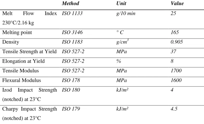
The polypropylene used is PPH9020 homopolymer from Total Petrochemical. Table 2.1 shows characteristics given by the supplier.
Table 2.1 Characteristics of the polypropylene used in this study
Method Unit Value
Melt Flow Index
230°C/2.16 kg
ISO 1133 g/10 min 25
Melting point ISO 3146 ° C 165
Density ISO 1183 g/cm3 0.905
Tensile Strength at Yield ISO 527-2 MPa 37
Elongation at Yield ISO 527-2 % 8
Tensile Modulus ISO 527-2 MPa 1700
Flexural Modulus ISO 178 MPa 1600
Izod Impact Strength (notched) at 23°C
ISO 180 kJ/m² 4
Charpy Impact Strength (notched) at 23°C
ISO 179 kJ/m² 4.5
1.2. Fibres
Flax 1.2.1.
Flax fibres were supplied by Dehondt Technologies (France) as NATTEX roving which were harvested in 2010 from Drakkar variety (France). These rovings were cut to a length of 0.5 mm by the company Apply Carbon (France). After these transformations, fibres appear as a mixture of thin and rather flexible elementary fibres and thick rigid bundles composed of elementary fibres “glued” together (Figure 2.1a). Bundles were partially separated during compounding (Figure 2.1 b).
25
Figure 2.1
Flax fibres: “mixture” of bundles and elementary fibres a) as delivered and b) after compounding (in polypropylene matrix)
Tencel 1.2.2.
These are man-made cellulose II fibres produced with Lyocell process, kindly provided by Lenzing AG (Austria). Tencel fibres are regenerated cellulose fibres formed in a wet fibre-formation process out of eucalyptus pulp dissolved in N-methylmorpholine-N-oxide monohydrate. They are individual flexible fibres with a diameter of 10 µm (Figure 2.2). Fibres with the average length of 500 µm (as given by the producer) were made from longer fibres by milling.
Figure 2.2
Tencel fibres a) as delivered and b) after compounding (in the matrix)
Glass fibres 1.2.3.
Glass fibres were kindly provided by Arkema. Fibres are of 2 500 µm as initial average length, 10 µm as diameter, 2.5 g/cm3 as density and 73 GPa as elastic modulus. Contrary to natural fibres, glass fibres show a straight shape (Figure 2.3.a) and a regular cross-section
a b
26 (Figure 2.3.b). Moreover, the density of glass fibres is 70 % higher than that of flax and Tencel.
Figure 2.3
Glass fibres: a) as delivered and b) after compounding
Decalin (decahydronaphthalene) was purchased from Sigma-Aldrich and used to dissolve polypropylene for the measurements of fibre size distribution.
2. Processing: compounding and injection moulding
2.1. Compounding
Principle 2.1.1.
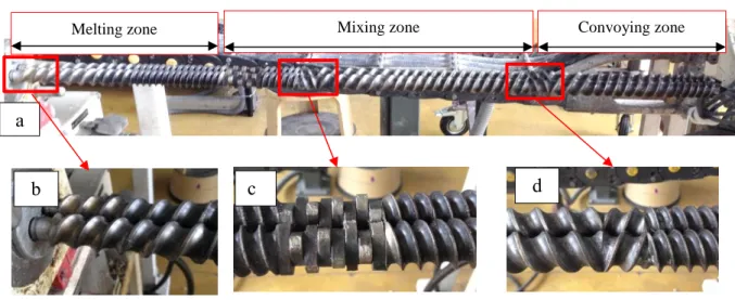
The purpose of compounding is to enable a good dispersion of fibres throughout a polymer melt. The twin screw extruder is usually used for composite compounding. Basically, a twin screw extruder consists of two parallel screws turning within a 8-shaped housing barrel. The most industrially used one has a corotating and intermeshing screws configuration. Screws and barrel may be built up from different segments. Barrel wall is usually smooth, but it can be constructed with longitudinal or helical grooves, for particular applications requiring an intensive shear rate solicitation. The screws are designed as three main zones from the inlet to the die: melting zone, mixing zone and conveying zone (Figure 2.4.a). The screws can be adjustable depending on the particular configuration of each zone. Conveying elements are used in melting and conveying zones (Figure 2.4.b). They may have different pitches and spacing between flights. Mixing zone contains reverse flight screw elements or kneading elements for more intensive mixing (Figure 2.4.c and d).
500 µm
27 Figure 2.4
Twin screw configuration a) main zones of screws b) convoying elements c) kneading elements d) reverse flight elements
Compounding conditions 2.1.2.
Four concentrations of fibres were prepared for each type of fibre, flax, Tencel and glass. Because of the difference in density between glass and cellulosic fibres, it is the volume fraction that was chosen to be the same (Table 2.2).
Table 2.2 Composite formulations
Volume fraction, %
Weight fraction, %
Flax Tencel Glass
3.6 5 5 9.3 6.3 10 10 15.6 13.1 20 20 29.4 20.5 30 30 41.6 a b Convoying zone Mixing zone Melting zone c d
28 For a better understanding of composite rheology, no coupling agent was used in composite formulation, with the purpose of not modifying the matrix viscosity when varying fibre concentration [Le Moigne et al. (2013)].
Before compounding, fibres were dried at 105 °C for 2 hours. Clextral BC21 extruder (Centre
des Matériaux, Ecole des Mines d’Alès) was used to prepare composites. It is a co-rotating
twin screw extruder with a centreline distance of 21 mm and a screw length of 900 mm. The global flow rate was 7 kg/h and the screw speed was 200 RPM. A dedicated feeder was operated to control the fibre feed rate relatively to the one of matrix, which enables to get the desired concentration. The screw profile (Figure 2.3.a) was built in Centre de Matériaux
d’Ales by combining conveying and mixing elements ensuring short residence time of fibres
to protect them from temperature degradation and breakage. The barrel temperature was progressively increased throughout 12 zones from 60 ° C to 190 ° C, as shown in Figure 2.5. The matrix and fibres were fed from zones 1 and 7, respectively.
zone 1 2 3 4 5 6 7 8 9 10 11 12 T°C 60 80 120 140 190 190 190 190 190 190 180 190
Figure 2.5
Screw profile used for composite compounding
At the die exit, composite was immediately quenched in water (Figure 2.6.a), then granulated into pellets whose size around 5 mm (Figure 2.6.a), as required by injection moulding processing. The maximum measured temperature was 195 °C. The relative rise in temperature with respect to the setting temperature is caused by the viscous heating.
29 Figure 2.6
a) A water bath used for cooling compound after extrusion b) obtained granules after pellitisizing
2.2. Injection moulding
2.2.1. Principle
The injection moulding process has been essentially made for unfilled thermoplastic materials. The same machines are used to process reinforced thermoplastics. Injection moulding machine can commonly be divided into two units: an injection unit and a clamping unit, as shown in Figure 2.7.
Figure 2.7
Injection moulding machine and its main constituents Compound granules
Hopper
Injection unit Clamping unit
Moveable platen holding the mould
Screw and barrel surrounded by heaters Nozzle
30 Clamping unit and mould
2.2.2.
The functions of the clamping unit are to open and to close the moveable platen that holds mould, and to eject components from the mould (Figure 2.8). Melts resin enters into mould from the sprue bushing which is directly connected with injection barrel by the nozzle. The sprue feeds the cavity through channels which are also referred as runners .The melt flows through the runners and arrives in the cavities by the gates. The entire design containing sprue, runners and cavities is machined out on the mould and the amount of melt needed to fill them is called “shot”. Ejection is possible by a sprue puller and ejector pins, also known as knock out pins, located throughout the cavity and the runners. A cooling system is passing water through series of channels drilled and connected in the mould to form a continuous pathway. The role of water is to keep the mould at a desired temperature in order to solidify the polymer. The mould description here is primary and simple. More tools can be used for complex moulds with sophisticated design. For example, sliders enabling side-actions can be put on the mould when the part shows undercuts.
Figure 2.8
A typical two plate injection mould including a cavity and its system of injection (sprue, runners and gate framed with the dashed line red rectangle)
Nozzle Water channels Sprue bushing Ejector pins Sprue puller Moveable platen Stationary platen Sprue Cavity Gate Runners
31 Injection unit
2.2.3.
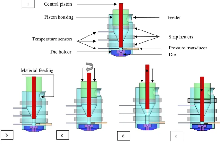
The injection unit functions are to plasticise material and to inject it into the mould. These functions are handled by a three-section-screw (feed, compression and metering) (Figure 2.9). Modern standard screws have an overall length of 20-23 D (length as a product of diameter). The length of the feed section is generally the half-length of the screw, while compression and metering sections accounting together the residual half-length and having approximately the same length. The pitch varies between 0.8-1 D from the feed to the metering zones across the screw flights.
Figure 2.9
Screw in injection moulding machine and its sequence during the injection moulding cycle [Rosoto et al. (2000)]
Figure 2.9 describes schematically the sequence of the screw along the cycle of injection moulding. At the beginning of cycle, the screw is at a retracted position in the barrel and the melt occupies the region between the screw tip and the nozzle (Figure.2.9.a). Then during injection the screw advances taking the function of piston when the mould halves closed and clamping force applied (Figure.2.9.b). This induces the material displacement through the nozzle and the filling of the mould cavity. Once the mould is filled, pressure is maintained in the injection cylinder till the material in the mould gates solidifies. During this holding stage,
Feed Metering Compression Barrel Nozzle Pitch Flight Composite granules Composite melt
32 an additional melt from the barrel compensates the polymer cooling shrinkage. After this stage a new dose of melt is prepared for the next injection cycle. The screw rotates enabling the material melting and mixing through its transfer from hopper to screw forward (Figure.2.9.c). Pressure generated in the melt transfer allows the retraction of screw in the barrel. This pressure can be varied by controlling the axial displacement of screw; this procedure is called the application of back pressure. Once the new dose is ready, the solidified part is ejected from the cavity and the mould is clamped again to start the subsequent cycle. As the screw comes forward, the melt can flow through its flights. A non-return valve is usually located to the front of the screw, preventing the melt backflow.
Injection moulding conditions 2.2.4.
The granules of composites were further processed in DK Codim NGH 110/200 injection machine (Figure 2.6), with 28 mm as screw diameter and 84 cm3 as practical shot volume. The injection moulded part is a “box” with dimensions of 175 mm x 71 mm x 59 mm (Figure 2.10). Table 2.3 regroups the injection moulding conditions.
Figure 2.10
Injection molded box, all dimensions are in mm
Transducer 1: X= 23, Y= 21, Z= 0
Transducer 2: X= 80, Y= 0, Z= 0
33 Table 2.3 Injection moulding conditions
Injection temperature, °C 190 Cooling time, s 10
Mold temperature, °C 30 Holding time, s 10
Flow rate, cm3/s 92.4 Holding pressure, bar 600
Shot length, mm 115 Back pressure, bar 0
Clamping force, KN 1100 Screw speed, RPM 120
Several pressure and temperature sensors were placed in and around the mould. Five pressure transducers are used: three transducers are located in the mould as shown in Figure 2.10, one is before the mould entrance at the nozzle and another one is placed in the hydraulic cylinder behind the screw. A temperature sensor was installed in the mould located at 2 cm from the cavity surface.
3. Characterisation
3.1. Fibre size analysis
Fibre length and diameter after compounding and after injection were determined as following: the composite was diluted with Decalin® to get a fibre concentration in the mixture (polypropylene, fibres and Decalin®) lower than 10 %, which avoids fibre overlapping and facilitates a later fibre size measurement. As shown in Figure 2.11, the mixture is placed in a ball-flask immersed in an oil bath and gently stirred during 2h under 170 °C (see more details in ref. LeMoigne et al. (2011); LeDuc et al. (2011); Soccalingame et al. (2015)).
34 Figure 2.11
Extraction of fibres from composites under a gentle stirring
A few drops of polypropylene-Decalin-fibre suspension were deposited on a glass plate and analysed in transmission optical microscopy by using Leica DP 4500 optical microscope equipped with a high resolution 3-CDD numerical camera (JVC KY-F75U, 1 360 x 1 024 pixels). The glass slide is held by a microscope stage that can be displaced in x and y directions as described in Figure 2.12. This displacement is controlled by a handed stage driver. The displacement of the stage is monitored by a position detector related to a computer, in which was installed Cartograph (Microvision®). Images were taken by the camera at each position of the stage. The focus is adjusted by moving the stage in the z direction. Cartograph enables to assemble the different images with respect to their positions in the specimen. A real time homogenization between the elementary images was performed automatically by a dedicated tool in Cartograph software.
Polypropylene+ fibres+ Decalin® (In the ball-flask)
Oil bath
Hot plate stirrer Condenser
35 Figure 2.12
Leica DP 4500 optical microscope equipped with accessories dedicated to perform specimen cartographies
The analysis of fibre size was then performed using cartography of ≃ 5 x5 mm² built-up from 50 elementary transmission images (830 µm x 640 µm) per composite formulation. The measurement of fibre size was done semi-automatically by Archimed (Microvision®), the image processing software dedicated to measurement. After selecting the fibre pattern “by hand”, a numerical calliper integrated in the image acquisition software allowed the measurement of each fibre length and diameter (Figure 2.13). The statistical analysis was based on 200 fibres per sample. Each formulation was analysed at least three times, giving the difference in the size within an uncertainty interval of 10 %. The minimal size that was taken into account was 10 µm.
The non-processed (initial) fibre size was analysed in the same way by dispersing fibres on a glass slide and using the cartography approach.
Numerical Camera
x y
y
Stage handed-driver
Stage position detector
Moving stage
z
Image acquisition and processing Specimen
36
Figure 2.13
A part of a cartography of flax-based composite obtained by assembling elementary images (dashed rectangles), the red numbers correspond to the measurements of fibre size (lines for
length and circle for diameter)
3.2. Microstructure analysis
A sample was cut at 70 mm from the gate in xy-plane of the injection moulded box as shown in Figure 2.14.a. It was then embedded with epoxy resin and polished to analyse the microstructure at different depths from the surface (Figure.2.14.b). Six layers down from the surface to the middle plane, at 100 µm, 200 µm, 400 µm, 600 µm, 800 µm and 900 µm (middle layer) were made, allowing the analysis of fibre orientation in planes parallel to the surface (xy plane in our case). We assumed the symmetric pattern of flow with respect to the middle plane. Two transverse cross sections in zy and zx planes were also analysed to have a 3D overview of the fibre orientation.
37 The preparation of the sample surface requires a great care to have a good image quality suitable for characterizing the fibre microstructure. The sample is firstly polished by abrasives, starting with coarse ones and finishing with fine ones, and secondly polished by diamond paste. At least a difference in depth of 100 µm was needed between two successive layers to avoid scratches and to get a polished surface plausible for analysing. The sample was analysed with optical microscopy in reflection mode, and 5 mm x 5 mm cartographies were recorded by assembling “elementary” images (Figure.2.14.c, see details in the section 3.1 Fibre size analysis). The obtained image was semi-automatically analysed by Archimed (Microvision®) software. Fully automatic measurements were not possible because of the variation of contrast within the fibres themselves and the irregularity of fibres shape. This aspect will be further discussed in Chapter 4.
Figure 2.14
A schematic representation of a sample cut from the injected box and polished as 6 layers in the flow xy-plane
(c) Cartography reconstruction
(b) Polishing (a) Sample cutting out