HAL Id: tel-02428796
https://pastel.archives-ouvertes.fr/tel-02428796
Submitted on 6 Jan 2020
HAL is a multi-disciplinary open access
archive for the deposit and dissemination of sci-entific research documents, whether they are pub-lished or not. The documents may come from teaching and research institutions in France or abroad, or from public or private research centers.
L’archive ouverte pluridisciplinaire HAL, est destinée au dépôt et à la diffusion de documents scientifiques de niveau recherche, publiés ou non, émanant des établissements d’enseignement et de recherche français ou étrangers, des laboratoires publics ou privés.
Forming of deep-parts in AA5383 alloy : experimental
and numerical approach
Rou Du
To cite this version:
Rou Du. Forming of deep-parts in AA5383 alloy : experimental and numerical approach. Other [cond-mat.other]. Ecole nationale supérieure d’arts et métiers - ENSAM, 2019. English. �NNT : 2019ENAM0030�. �tel-02428796�
Arts et Métiers ParisTech – Campus d’Angers
Laboratoire Angevin de Mécanique, Procédés et innovAtion (LAMPA)
2019-ENAM-0030
École doctorale n° 432 : Sciences des Métiers de l’ingénieur
Jury
Mme Anne Marie HABRAKEN, Directrice de recherches FNRS, ArGEnCo, Université de Liège Président Mme Sandrine THUILLIER, Professeur des Universités, IRDL, Université Bretagne Sud Rapporteur M. Abel CHEROUAT, Professeur des Universités, Institut Charles Delaunay, U.T. de Troyes Rapporteur M. Arnaud DELAMEZIERE, Professeur de Institut Supérieur d'Ingénierie de la Conception, LEM3 Examinateur
M. Yessine AYED, Maître de conférences, LAMPA, ENSAM Angers Examinateur
M. Charles MAREAU, Maître de conférences, LAMPA, ENSAM Angers Examinateur
M. Philippe DAL SANTO, Professeur des Universités, LAMPA, ENSAM Angers Examinateur
Mme Eliane GIRAUD, Maître de Conférences Invité
T
H
È
S
E
Doctorat
T H È S E
pour obtenir le grade de docteur délivré par
l’École Nationale Supérieure d'Arts et Métiers
Spécialité “ Mécanique-Procédés de fabrication ”
présentée et soutenue publiquement par
Rou DU
Le 27 Septembre 2019
Forming of deep-parts in AA5383 alloy:
Experimental and numerical approach
Directeur de thèse : Philippe DAL SANTO
ACKNOWLEDGEMENTS
This PhD research has been performed in the laboratory of LAMPA (Laboratoire Angevin de Mécanique et innovAtion), ENSAM (Ecole Nationale Supérieure d’Arts et Métiers). By this chance, I’d like to give my sincere acknowledgements.
First of all, I would like to express my gratitude to my supervisor, Philippe DAL SANTO, who offered me this precious chance to have a research on hot sheet metal forming. I will always be grateful for his helps and encouragements during the process of the thesis.
In addition, I appreciate my two co-supervisors, Charles MAREAU and Yessine AYED, for their valuable comments and modifications in the manuscripts. Especially thanks Charles for opening a door to me on the knowledge of mechanics and giving me the courage to carry on. Also, I’d like to give thanks to Eliane GIRAUD for her help in the experimental part during my first two years.
Furthermore, I would like to thank Sandrine THUILLIER and Abel CHEROUAT for being my reporters and giving so many good suggestions for my research and manuscript. I also appreciate Anne Marie HABRAKEN and Arnaud DELAMEZIERE for being my jury members and making those precious comments.
A great thank to Fisher CYRIL, Linamaria GALLEGOS and Idriss TIBA for the help in my experimental tests. Also thanks Jérôme for helping me machine so many specimens.
Thanks Frank MOREL, the director of the lab, for welcoming me well in the team of LAMPA. I would also like to express my great appreciate to the colleagues of LAMPA for a lot of happy moments and giving me this agreeable and unforgettable memory: Xiaoyu, Hela, Arine, Foued, Driss, Bessam, Siti, Imane, Duc, Camille, Benoit, Hugo, Racha, Houssem, Amandine, Sana, Vincent, Antoine, Amine, Daniel, Wael, Benjamin, Mariem, Edouard, Imed, Jihed, Aziz, Mathild, HD, Etienne, Javier, Ali, Julien, ...
In addition, I want to thank China Scholarship Council for the financial support during this PhD research.
In the Last, I would like to thank my parents and brother for their support to continue this PhD. Mostly, I want to express my sincere gratitude to my wife, who is always there to support me, to give me strength and to raise me up when I am down.
Content List
List of Figures ... I List of Tables ... IV List of notations ... V
Chapter I. General introduction ... 1
I.1 Background and motivation ... 1
I.2 Thesis objective ... 2
I.3 Outline of the present thesis ... 3
Chapter II. Literature review ... 5
II.1 Hot forming in the industry ... 5
II.1.1 Stamping ... 6
II.1.2 Hydroforming ... 8
II.1.3 Incremental forming ... 9
II.1.4 Superplastic forming ... 10
II.1.5 Quick plastic forming ... 13
II.1.6 Hybrid forming technique ... 14
II.1.7 Synthesis ... 16
II.2 Constitutive models for hot forming ... 17
II.2.1 Phenomenological constitutive models ... 17
II.2.2 Physically-based Models ... 22
II.2.3 Artificial neural network (ANN) approach ... 27
II.3 Yield criteria ... 28
II.3.1 Anisotropy coefficients ... 29
II.3.2 Yield criteria ... 30
II.4 Damage models ... 32
II.4.1 Foreword ... 32
II.4.2 Uncoupled ductile fracture criteria ... 34
II.4.3 Coupled ductile fracture criteria ... 36
II.5 Mechanical behavior of Al-Mg alloys at elevated temperatures ... 39
II.5.1 Al-Mg alloys behavior in warm forming conditions ... 39
II.5.2 Al-Mg alloys behavior in hot forming conditions ... 40
II.6 Summary ... 42
Chapter III. Experimental investigation of the high temperature behavior of the AA5383 alloy .. ... 44
III.1 Metallurgical characteristics of the AA5383 alloy ... 44
III.1.1 As-received material ... 44
III.1.2 Heat-treated material ... 45
III.2.1 Specimen geometries ... 47
III.2.2 Testing machines ... 48
III.3 Flow behavior of the AA5383 alloy ... 50
III.3.1 Uniaxial tension ... 50
III.3.2 Biaxial tension ... 55
III.4 Damage behavior of the AA5383 alloy ... 56
III.4.1 Influence of the stress state ... 56
III.4.2 Influence of temperature and strain rate ... 60
III.5 Summary ... 61
Chapter IV. Material models for AA5383 alloy at high temperature deformation ... 63
IV.1 Identification strategies... 63
IV.2 Constitutive model ... 64
IV.2.1 Flow behavior ... 64
IV.2.2 Yield function criteria ... 68
IV.2.3 Implementation of constitutive model ... 73
IV.3 Damage model ... 78
IV.3.1 Determination of equivalent fracture strain ... 78
IV.3.2 Proposed damage model ... 86
IV.4 Summary ... 92
Chapter V. Numerical simulation and experimental forming ... 94
V.1 Numerical simulation of the forming process ... 94
V.1.1 Material models ... 94
V.1.2 Simulation of the forming process ... 95
V.1.3 Forming pressure control strategies ... 96
V.1.4 Different integration point number selections ... 99
V.1.5 Different strain rate approaches ... 101
V.2 Experimental bulging tests ... 102
V.2.1 Experimental forming conditions ... 102
V.2.2 Experimental results ... 103
V.3 Comparison between forming experiments and simulations ... 109
V.3.1 Axisymmetric shape forming ... 109
V.3.2 Cross shape forming ... 110
V.4 Summary ... 112
Conclusion and perspectives ... 114
Appendix ... 117
I
List of Figures
Figure I-1 Example of a deep-drawing part in aluminum alloys for (a) aeronautic and (b) automotive
application ... 1
Figure I-2 Principle of Superplastic Forming (SPF) [7] ... 1
Figure I-3 Principle of the complex parts forming using combined process (warm deep-drawing followed by superplastic forming) [10] ... 2
Figure I-4 Summarized structure of the information presented in this document ... 4
Figure II-1 Application of aluminum alloy panel structures in (a) automobile [12] and (b) aircraft [13]. ... 5
Figure II-2 Classifications of elevated temperature forming techniques [14] ... 6
Figure II-3 Schematic of non-isothermal warm stamping [19] ... 7
Figure II-4 (a) Improved uniaxial ductility of warm forming [16]; (b) Improved forming limits in warm forming conditions [20] ... 7
Figure II-5 Comparisons between conventional deep drawing and sheet hydroforming [23] ... 8
Figure II-6 Schematics of incremental sheet forming with various tooling configuration [28] ... 9
Figure II-7 Superplastic deformation in a Cu-Al alloy [32] ... 10
Figure II-8 Evolution of microstructure and texture during superplastic deformation[33] ... 10
Figure II-9 Schematic of superplastic forming [36] ... 11
Figure II-10 (a) Principle of Constrained Groove Pressing [38] and (b) Illustration of grain modification in a magnesium alloy (AZ31B) [8] ... 12
Figure II-11 Schematic of quick plastic forming [43] ... 14
Figure II-12 Schematic of the hot draw mechanical pre-forming process (a) the sheet is first loaded into the die set; (b) a drawing stage pre-forms the panel and (c) a gas forming stage completes the forming operation [9] ... 15
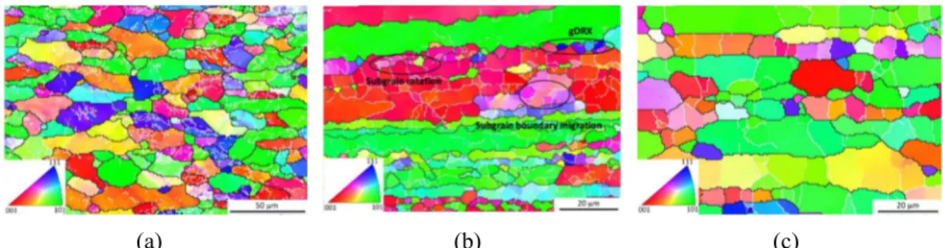
Figure II-13 A EBSD map of annealed AA5083 alloy (a) before forming; (b) after hot stamping (pre-forming) and (c) end of gas forming [47] ... 15
Figure II-14 Comparisons between the experimental (solid lines) and modified JC model predicted (solid symbols) flow curves of AA6026 at (a) 673 K; (b) 723 K; (c) 773 K; (d) 823 K [51] ... 19
Figure II-15 Comparisons between predicted and measured flow stress curves of AA2030 at strain rates of : (a) 0.005 s-1; (b) 0.05 s-1 and (c) 0.5 s-1 [65] ... 21
Figure II-16 Comparison between experimental and predicted flow stress for AA7050 alloy, using modified ZA model at elevated temperature at (a) 0.001 s-1; (b) 0.01 s-1; (c) 0.1 s-1 and (d) 1.0 s-1 [57] .. ... 24
Figure II-17 Typical flow stress curve at the elevated temperature [70] ... 25
Figure II-18 Comparisons between the predicted and experimental flow stress of the Al-Mg-Zn-Cu alloy at the temperature of (a) 350 oC; (b) 400 oC; (c) 450 oC and (d) 470 oC [83] ... 26
Figure II-19 Schematic structure of back propagation neural network [84] ... 27
Figure II-20 Comparisons between the experimental (solid lines) and predicted (points) flow stress of Al-Cu-Mg-Ag alloy at (a) 0.001 s-1 and (b) 0.1 s-1 [84] ... 28
Figure II-21 Orthotropic axes of the rolled sheet metals: LD-longitudinal direction; TD-transversal direction and ND-normal direction ... 29
Figure II-22 Stages of ductile fracture [100] ... 32
Figure II-23 Conditions of temperature and strain rate for the appearance of St-St marks [129] ... 39
Figure II-24 Effect of strain rate and temperature on (a) strain hardening (n-value) and (b) strain rate hardening (m-value) of 5083-O Al-Mg alloy sheet in uniaxial tension tests [129] ... 40
Figure II-25 The grain map of the AA5083 alloy at different state (a) as received type and (b) after heating for 360 s at 450 oC [137] ... 41
Figure II-26 (a) Flow curves of superplastic AA5083 alloy at various strain rates and 450 oC [137]; (b) Flow curves of Al-5 wt.% Mg alloy at different temperatures and a strain rate of 0.1 s-1 [139] ... 42
Figure III-1 Metallographic observation of the as-received AA5383 alloy ... 45
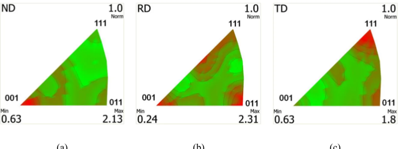
Figure III-2 Inverse pole figures of as-received material for (a) normal direction; (b) rolling direction and (c) transverse direction ... 45
II
Figure III-3 Metallographic observations of the AA5383 alloy after heat treatment at 623 K for (a) 5
min; (b) 30 min and (c) 60 min ... 46
Figure III-4 Inverse pole figures of material heat treated at 623 K for 5 min for (a) normal direction; (b) rolling direction and (c) transversal direction ... 46
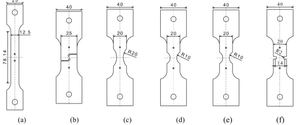
Figure III-5 Specimen geometries for testing: (a) UT specimen; (b) SH specimen; (c) NT20 specimen; (d) NT10 specimen; (e) NT5 specimen and (f) NT2 specimen. Blue slid dots highlight the position of the extensometer for relative displacement measurement ... 48
Figure III-6 (a) Gleeble 3500 and (b) schematic diagram ... 48
Figure III-7 Fixed position of the specimen in the GLEEBLE ... 49
Figure III-8 (a) LVDT Extensometer and (b) C gauge Extensometer ... 49
Figure III-9 (a) Gas forming machine at LAMPA and (b) pressure scheme ... 50
Figure III-10 Temperature evolution for uniaxial tension test ... 52
Figure III-11 Stress-strain curves obtained from UT tests at (a) 623 K; (b) 673 K and (c) 723 K ... 53
Figure III-12 Metallographic observations of deformed specimens at different temperatures and strain rates. (a) 623 K and 0.0001 s-1; (b) 623 K and 0.1 s-1; (c) 673 K and 0.0001 s-1; (d) 673 K and 0.1 s-1; (e) 723 K and 0.0001 s-1; (f) 723 K and 0.1 s-1 ... 54
Figure III-13 Stress-strain curves obtained from UT tests at 673 K and 0.001s-1 for different directions. ... 55
Figure III-14 Dome height-time curves obtained from FB tests ... 56
Figure III-15 Detailed geometry of SH specimen ... 57
Figure III-16 Force-displacement curves for shear test at 673 K and 0.001 s-1 ... 58
Figure III-17 Force-displacement curves for (a) UT tests and (b) different NT tests at 673 K and 0.001 s-1 ... 58
Figure III-18 Experimental fracture initiation deformed at 673 K and 0.001 s-1 for (a) NT20; (b) NT10; (c) NT5 and (d) NT2 specimens ... 59
Figure III-19 (a) Pressure evolution; (b) force-displacement curve for FB test deformed at 673 K and 0.001 s-1 ... 60
Figure III-20 Fractured specimen for FB test deformed at 673 K and 0.001 s-1 ... 60
Figure III-21 Force-displacement curves for NT20 specimen deformed at (a) 0.001 s-1 and (b) 673 K .. ... 61
Figure IV-1 Parameters of Arrhenius model as the function of equivalent plastic strain ... 66
Figure IV-2 Comparison between the experimental results and calculated stress-strain relations by the strain-compensated Arrhenius model at: (a) 623 K; (b) 673 K; (c) 723 K ... 67
Figure IV-3 Comparison between the experimental results and calculated stress-strain relations by composite model at: (a) 623 K; (b) 673 K; (c) 723 K ... 68
Figure IV-4 Flow chart for the BBC2003 criterion identification ... 71
Figure IV-5 (a) Geometry and (b) simulation model for free bulging ... 71
Figure IV-6 Results of inverse analysis for free bulging: experimental date vs. numerical design for forming pressure at (a) 0.6 MPa; (b) 1.0 MPa and (c) 1.5 MPa ... 72
Figure IV-7 (a) Yield stress and (b) yield locus of AA5383 alloy predicted by Hill48 criterion and BBC2003 criterion ... 73
Figure IV-8 Flow chart of calculation in the UMAT subroutine ... 74
Figure IV-9 Numerical results of NT20 at different mesh sizes: (a) force and equivalent plastic strain vs displacement curves and (b) stress triaxiality vs displacement curve ... 79
Figure IV-10 Comparison of stress triaxiality evolution between 3D and 2D FE simulations ... 79
Figure IV-11 (a) Numerical model and (b) equivalent plastic strain distribution at the instant of failure for SH specimen ... 80
Figure IV-12 Experimental and numerical force-displacement comparison and the evolution of the equivalent plastic strain deformed at 673 K and 0.001 s-1 for SH specimen ... 80
Figure IV-13 Numerical models for different tension specimens: (a) UT; (b) NT20; (c) NT10; (d) NT5 and (e) NT2 ... 81
Figure IV-14 Equivalent plastic strain distribution at the instant of failure for different notched specimens: (a) UT; (b) NT20; (c) NT10; (d) NT5 and (e) NT2 ... 82
Figure IV-15 Force-displacement curves and the equivalent plastic strain evolution for tension specimens at 673 K and 0.001 s-1: (a) UT; (b) NT20; (c) NT10 and (d) NT5 ... 83
III
Figure IV-16 Pressure-displacement curves and evolution of equivalent plastic strain for free bulging at 673 K and 0.001 s-1 ... 84
Figure IV-17 Force-displacement curves and evolution of the equivalent plastic strain for NT20 at different temperatures and strain rates ... 85 Figure IV-18 Evolution of the stress triaxiality and the corresponding average values for different shapes of specimen deformed at 673 K and 0.001 s-1... 88
Figure IV-19 Comparison between the fracture locus against stress triaxiality obtained from the MMC criterion and the experimental data at: (a) 673 K and 0.001 s-1; (b) different temperatures and (c)
different strain rates ... 89 Figure IV-20 Force-displacement curves for different shapes of specimen at 673 K and 0.001 s-1: (a)
SH; (b) UT; (c) NT20; (d) NT10 and (e)NT5 ... 90 Figure IV-21 Force-displacement for NT20 at different temperatures and strain rates: (a) 623 K and 0.001 s-1; (b) 723 K and 0.001 s-1; (c) 673 K and 0.0001 s-1; (d) 673 K and 0.001 s-1; (e) 673 K and
0.01 s-1; (f) 673 K and 0.1 s-1 ... 91
Figure IV-22 Experimental and numerical results for NT2 specimen at 673 K and 0.001 s-1: (a)
force-displacement curves; (b) numerical equivalent plastic strain distribution and (c) experimental specimen at the initiation of fracture ... 92 Figure V-1 Numerical models used for forming simulation. (a) Axisymmetric shape; (b) Cross-shape .. ... 95 Figure V-2 Pressure algorithm ... 98 Figure V-3 Comparison of different pressure control schemes for (a) pressure evolution and (b) strain rate ratio evolution ... 99 Figure V-4 Pressure time curves obtained by new pressure control strategy with different integration point numbers for obtaining the targeting strain rate ... 100 Figure V-5 Comparison of three different strain rate simulations for axisymmetric shape forming: (a) deformed specimen; (b) pressure evolution; (c) maximum principal real strain and (d) thickness distribution. ... 102 Figure V-6 (a) Axisymmetric die; (b) Cross Die and (c) Configuration for forming experiment ... 103 Figure V-7 (a) Experimental pressure evolution and (b) the deformation for the axisymmetric shape .... ... 104 Figure V-8 Experimental results for axisymmetric forming measured by GOM software. (a) Maximum principal real strain field distribution; (b) Maximum principal real strain and (c) Thickness from the center point to the board ... 105 Figure V-9 (a) Experimental pressure evolution and (b) the deformed plate for the cross die deformed at constant low strain rate ... 106 Figure V-10 Experimental results for cross shape forming measured by GOM software. (a) Maximum principal real strain field distribution; (b) maximum principal logarithmic strain and (c) thickness evolution at the bottom of deformed part ... 107 Figure V-11 (a) Experimental pressure evolution and (b) the deformed plate for the cross die deformed at changed strain rate ... 108 Figure V-12 Experimental results for cross-shape forming measured by GOM software. (a) Maximum principal real strain field distribution; (b) maximum principal logarithmic strain and (c) thickness evolution from the center point to the board ... 109 Figure V-13 Comparison between experiment and simulation for axisymmetric shape forming
regarding (a) principal logarithmic strain and (b) thickness distribution ... 110 Figure V-14 Numerical cross shape forming at the low constant strain rate ... 111 Figure V-15 Comparison for cross shape forming between experiment and simulation : (a) maximum principal logarithmic strain and (b) thickness ... 111 Figure V-16 Pressure evolution for cross-shape forming by using changed strain rate and low constant strain rate strategies ... 112
IV
List of Tables
Table II-1 Superplastic alloys and corresponding superplastic forming conditions [41] ... 13
Table II-2 Comparison of SPF and QPF process by Krajewski and Schroth [42] ... 13
Table II-3 Brief summary of selected typical DFCs... 33
Table III-1 Chemical composition of AA 5383 alloy (wt. %) ... 44
Table III-2 Testing conditions for UT test along the rolling direction ... 51
Table III-3 Yield stresses and Lankford coefficients at 673 K and 0.001 s-1 ... 55
Table III-4 Testing temperatures and strain rates for NT20 specimen ... 61
Table IV-1 Parameter identification strategy for AA5383 alloy ... 64
Table IV-2 Material parameters for strain-compensated Arrhenius model ... 66
Table IV-3 Material parameters for the composite model ... 68
Table IV-4 Calculated Hill48 parameters for AA5383 alloy ... 69
Table IV-5 BBC2003 anisotropic parameters for AA5383 alloy ... 72
Table IV-6 Mesh size and element number for the FE model of NT20 specimen at 673 K and 0.001 s-1 ... 78
Table IV-7 Summary of the equivalent fracture strains for different shapes and deformation temperatures and strain rates ... 85
Table IV-8 Identified parameter values of MMC criterion and the corresponding residual value ... 88
Table V-1 Summary of the material models used for forming simulations ... 94
V
List of notations
Symbols Description Units
Parameter of the Arrhenius model [-]
Parameter of the Arrhenius model [-]
ˆ
Parameter of the composite model [-]
or Plastic multiplier [-]
Total strain tensor [-]
e Elastic strain tensor [-]
P Plastic strain tensor [-]
Logarithmic strain [-]
P
Equivalent plastic strain [-]
P f
Equivalent fracture strain [-]
P
Equivalent plastic strain rate [s-1]
p Plastic strain rate tensor [s-1]
Stress triaxiality [-]
Lode angle [°]
Lode angle parameter [-]
, Lamé’s first and second parameter [Pa]
Poisson’s ratio [-]
Normalized third stress invariant [-]
Dislocation density [-]
Stress tensor [MPa]
Axial Cauchy stress [MPa]
Equivalent stress [MPa]
m
Mean stress [MPa]
'
Effective stress tensor [MPa]
n
Normal stress [MPa]
Shear stress [MPa]
Plastic flow potential [-]
Yield function [-]
Elastic stiffness tensor [1/MPa]
a Parameter of the BBC2003 yield criterion [-]
VI
A Parameter of the modified Mohr-Coulomb criterion [MPa]
ˆb Burger’s vector [-]
b Parameter of the composite model [-]
C
C Critical value for ductile fracture criteria [-]
1, ,2 3
c c c Parameters of the modified Mohr-Coulomb criterion [-]
D Damage state variable [-]
D Damage evolution [s-1]
1
D
,D
2 Parameters of the modified Mohr-Coulomb criterion [-]E Young’s modulus [GPa]
F Parameter of the Hill48 yield criterion [-]
D
F Damage dissipative potential [-]
G Parameter of the Hill48 yield criterion [-]
H Parameter of the Hill48 yield criterion [-]
3
J Third deviatoric stress invariant [MPa]
k Integer parameter of the BBC2003 yield criterion [-]
K Parameter of the composite model [MPa]
L Parameter of the Hill48 yield criterion [-]
m Parameter of the composite model [-]
ˆ
M
Parameter of the Hill48 yield criterion [-]M Parameter of the BBC2003 yield criterion [-]
n Parameter of the Arrhenius model [-]
ˆn Parameter of the composite model [-]
n Parameter of the modified Mohr-Coulomb criterion [-]
n Flow direction [-]
ˆ
N
Parameter of the Hill48 yield criterion [-]N Parameter of the BBC2003 yield criterion [-]
p Hydrostatic pressure [MPa]
P Parameter of the BBC2003 yield criterion [-]
ˆP
Forming pressure [MPa]ˆ
Q Activation energy [kJ mol-1]
Q Parameter of the BBC2003 yield criterion [-]
0, ,45 90
r r r Lankford coefficient [-]
b
r Biaxial r-value [-]
VII
ˆR
Parameter of the BBC2003 yield criterion [-]S Parameter of the BBC2003 yield criterion [-]
T Testing temperature [K]
ˆ
T Parameter of the BBC2003 yield criterion [-]
ref T Reference temperature [K] m T Melting temperature [-] 0 45 90 , , , , b
Y Y Y Y Y Yield stress [MPa]
Z Zener-Hollomon Parameter [-]
'
1
Chapter I.
General introduction
I.1 Background and motivation
Due to the concerns of environmental protection and stringent requirements of greenhouse gas emissions, weight reduction is a major issue for transportation. Application of lightweight material, such as aluminum, magnesium alloys or composites is an efficient strategy that can help to meet the climate challenge. Among the family of lightweight material, aluminum alloys have been extensively used in the automotive and aircraft industry due to the advantages of low density, high strength to weight ratio, good corrosion resistance and a reasonably low cost [1].
(a) (b)
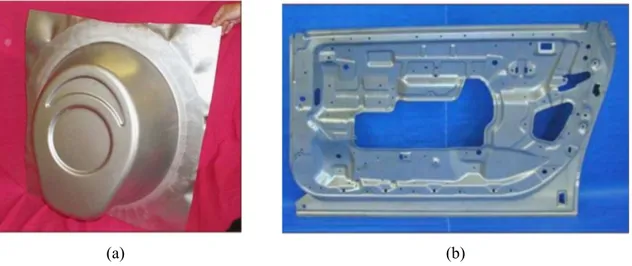
Figure I-1 Example of a deep-drawing part in aluminum alloys for (a) aeronautic and (b) automotive application
Major challenge of application of aluminum alloys in automotive and aeronautic industries lies in the ability to form deep-drawing shapes, as illustrated in Figure I-1. Superplastic Forming (SPF) is widely used to produce this type of parts as shown in Figure I-2 [2-6]. SPF consists in applying, on a flange, a gas pressure at a predefined strain rate to realize the deformed shape [7]. Amongst the advantages of such process are: functions integration, high formability and surface quality. The most critical issue of this process is the inherent high forming time due to the applying of low strain rates to avoid void growth and premature failure.
Figure I-2 Principle of Superplastic Forming (SPF) [7]
Argon gas pressure Furnace
Thin sheet Die
2
I.2 Thesis objective
The present dissertation focuses on hot forming strategies to produce deep drawing parts from AA5XXX aluminum thin sheets. The main objective is to reduce the forming time without sacrificing the part integrity. Different approaches can be considered:
A modification of the alloy characteristics to extend its superplastic field range in terms of temperature and strain rate.
A pre-deformation of the sheet using hot stamping process before the superplastic operation. The use of another forming technique like incremental sheet forming.
The first approach lies in the modification (i.e. the refining) of the granular structure of the alloy before the forming. Decrease in grain size eases superplastic deformation which can thus be activated for lower temperatures and higher strain rates. These new thermomechanical conditions allow decreasing significantly the forming time. Constrained Groove Pressing, a severe plastic deformation technique for the thin sheet, has been recently developed to refine the initial microstructure [8]. The second approach consists in chaining two processes [9, 10], shown in Figure I-3. A first hot deep-drawing operation allows obtaining a preformed geometry with low curvature. This operation is then followed by a superplastic operation which completes the part shape realizing the localized details. For the first operation, the deformation is realized by the mechanical action of a punch, whereas, for the second operation, the deformation is realized by applying a controlled gas pressure. This leads to a change in strain rate (from high rate to low one), which allows reducing the process time. The third approach consists in using Incremental Sheet Forming process to produce complex deep parts. This technique has numerous advantages compared to superplastic forming: in particular, the absence of die and a forming at room temperature. However, some surface defects can be generated depending on the manufacturing conditions (ex.: toolpath, speed rate, tool rotation…) [11].
(a) (b) (c)
Figure I-3 Principle of the complex parts forming using combined process (warm deep-drawing followed by superplastic forming) [10]
In the present study, the second approach using the gas quick plastic forming as the pre-forming step is carried out to form complex deep parts in AA5383 alloy. The main scientific issues of this research work are summarized as follows:
3
(1) To understand the influence of the thermomechanical history of the alloy on its superplastic behavior.
(2) To propose a rheological model describing the behavior of the alloy for a wide range of thermomechanical conditions.
(3) To complete the previous model by including uncoupled damage predicting the failure behavior of the alloy under all its loading conditions.
(4) To develop a numerical tool allowing the chaining of the concerned processes.
I.3 Outline of the present thesis
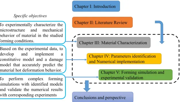
The outline of this document is shown in Figure I-4. The work performed during the PhD dissertation is introduced in Chapter I. Next, chapter II presents the literature review about current research statement, including hot forming techniques, constitutive model, damage model and some properties for 5xxx aluminum alloys. In chapter III, our researched material AA5383 alloy is characterized, including microstructural and mechanical approaches. The mechanical experiments consist of flow behavior, yield function and damage analysis. Chapter IV focuses on material identification and numerical implementation of the studied models. Based on the experimental results, the behavior laws are presented. The BBC2003 yield criterion with a composite hardening model is employed to describe the mechanical response. Their implementation, in the finite element code ABAQUS©, is realized through a user defined subroutine (UMAT). The damage behavior is described by the modified Mohr Coulomb criterion. The fracture model parameters are identified from the loading paths extracted from numerical simulations with shell elements. The influence of temperature, strain rate and stress triaxiality are investigated. Hot forming simulations and corresponding experiments are carried out in Chapter V. The forming strategies are evaluated and the comparison between the experimental and numerical results is discussed. Lastly, the main conclusions and perspectives are presented.
4
Figure I-4 Summarized structure of the information presented in this document
Chapter II: Literature Review Chapter I: Introduction
Chapter III: Material Characterization
Chapter IV: Parameters identification and Numerical implementation
Chapter V: Forming simulation and experimental validation
Conclusions and perspective Specific objectives
To experimentally characterize the microstructure and mechanical behavior of material in the studied forming conditions.
Based on the experimental data, to develop and implement a constitutive model and a damage model that accurately predict the material hot deformation behavior. To perform complex forming simulations with identified models and validate the numerical results with corresponding experiments
5
Chapter II. Literature review
In this chapter, the sheet metal forming techniques, which are commonly used in industry, are first presented. Specific care is taken to discuss the advantages and disadvantages of each of these forming techniques. Then, the constitutive models for metallic alloys in the hot temperature deformation range are described. Also, since another important issue for metal forming is the accurate prediction of ductile fracture, a brief overview of ductile fracture and damage criteria is given. Two different types of approaches are considered: the uncoupled approach and the coupled approach. The last section focuses on the specific features of the behavior of AA5xxx aluminum alloys at elevated temperatures.
II.1 Hot forming in the industry
The need for light metallic alloys in the automotive and aerospace industry has recently increased for both structural and body parts. Wrought aluminum alloys are the most popular raw material for panel structures. Generally, both non-heat treatable AA5xxx, and heat treatable AA6xxx, AA7xxx and AA2xxx are widely used for automotive and aircraft applications, as shown in Figure II-1.
It should be noticed that the workability of an alloy determines its application. For high strength aluminum alloys, which have similar strength levels to conventional mild steel, the ductility is poor at room temperature. These alloys are therefore unable to sustain large deformations and are poor candidates for the manufacturing of complex shaped parts. To circumvent the difficulties, some advanced forming techniques have been developed. The commonly used sheet metal forming techniques for wrought aluminum alloys and the strategies to improve the forming efficiency are discussed in this section.
(a) (b)
Figure II-1 Application of aluminum alloy panel structures in (a) automobile [12] and (b) aircraft [13]
6
To solve the problem of ductility and provide the possibility of manufacturing complex-shaped components, aluminum alloys are often formed at elevated temperatures. The ductility is increased and the strength is reduced with increasing forming temperature. Different elevated temperature forming techniques have been extensively investigated and used for industrial applications. The classification map of different forming techniques according to the approximate temperature and strain rate is shown in Figure II-2 [14]. For aluminum alloys, the elevated temperature forming techniques can be further divided into warm and hot forming conditions with traditional forming processes. Generally, warm forming refers to the case when the temperature is comprised between 0.3 times of the melting temperature and the recrystallization temperature [15]. For hot forming techniques, the temperature is selected to be above the recrystallization temperature and below the solidus temperature. The specific case of semi-solid forming (i.e. above the solidus temperature) is not considered in this review.
Figure II-2 Classifications of elevated temperature forming techniques [14]
II.1.1 Stamping
The most commonly used sheet metal forming technique is stamping of sheet alloys at warm temperature using conventional rigid dies. Based on the die temperature, the process can be divided into isothermal and non-isothermal conditions. The typical non-isothermal warm stamping forming process is shown in Figure II-3. The blank sheet is heated to an elevated temperature by an external furnace while the die is kept at room temperature by cooling water. The warm stamping process has some advantages, including higher material ductility and forming limit (shown in Figure II-4) [16], less spring back effect compared to cold stamping [17], increase of drawability due to non-uniform temperature distribution [18], higher manufacturing efficiency compared to warm hydro-forming and warm incremental forming. However, there are some limitations for warm stamping forming, such as the fact that it is not suitable for high-strength heat treatable aluminum alloys and the need for high-temperature lubricants.
7
Figure II-3 Schematic of non-isothermal warm stamping [19]
(a) (b)
Figure II-4 (a) Improved uniaxial ductility of warm forming [16]; (b) Improved forming limits in warm forming conditions [20]
To extend the applications of aluminum alloys in the transportation industry, hot stamping has been developed to form high-strength heat treatable aluminum alloys at higher temperatures than conventional warm stamping forming. Two typical hot stamping techniques exist: the Hot Form and Quench technique proposed by Lin et al. [21] and the hot stamping process proposed by Maeno et al. [22]. For the Hot Form and Quench process, the blank is firstly heated to its solution heat treatment temperature which is kept constant for a specific time to dissolve the coarse precipitates within the α-Al matrix. The blank is then quickly stamped and quenched by holding it with the cold dies for a short period of time. The high cooling rate obtained with quenching allows preventing the formation of a coarse secondary phase at grain boundaries. The hot stamped part can be artificially aged to achieve higher strength to meet the design requirement of vehicle manufacturers. For the other typical hot stamping forming technique of Maeno et al. [22], the process uses a T4 condition and a quick heating below the solution treatment temperature. The following steps are stamping and artificial aging. Aluminum alloy aircraft parts with a high strength and dimensional accuracy can be successfully produced with this process.
8 II.1.2 Hydroforming
Sheet hydroforming is a metal forming technology originating from the hydroforming technology which was first developed in the 1990s [23]. A typical forming method in sheet hydroforming techniques is hydrodynamic deep drawing, shown in Figure II-5. In this forming process, oil or any other pressuring liquid media are used to press the sheet metal tightly onto the punch where it is drawn into the die by a rigid punch. The liquid medium in the die cavity can reduce the friction between the sheet metal and die, leading to a higher drawing ratio value of the sheet metal. The quality of the part can also be improved.
There are some advantages of sheet hydroforming:
Friction at the flange can be reduced due to fluid lubrication Draw-ability can be significantly increased
Reduced surface defects of the formed parts due to the liquid pressure medium Fewer dies are used thus reducing the tool cost
Despite the above advantages, some drawbacks also exist for sheet hydroforming. The manufacturing efficiency is low, especially for the automotive industry and the manufacturing cost per part is high when compared to conventional stamping forming processes. Even though the shape distortion and spring back can be eliminated with sheet hydroforming, an additional heat treatment process is needed to restore the component strength, resulting in an additional cost.
For the warm sheet hydroforming technique, the blank is simultaneously heated with forming dies using an external furnace [24] or heating bands [25]. In comparison with cold hydroforming, warm hydroforming uses the improved formability of aluminum alloys at elevated temperatures, which is especially effective for high strength aluminum alloys, like AA6xxx and AA7xxx with poor formability at room temperature [26]. It should be noticed that for warm hydroforming, the forming temperature depends on the pressurizing medium sustainable temperature. The conventional oil medium temperature is below 300oC, which means that sheet hydroforming is not suitable for the hot forming temperatures.
9 II.1.3 Incremental forming
Incremental forming was first introduced by Matsubara in 1993 [27]. The process can be divided into different types according to the tool configuration [28], shown in Figure II-6. Single point incremental forming is the most commonly used technique. During the process, the blank holder is used to clamp and hold the blank sheet in position. The rotating single point forming tool is utilized to progressively form the sheet into a component and its path is generated by a computer numerically controlled (CNC) machining center. During the incremental forming process, no backup die is used to support the bottom surface of the deformed sheet. The advantages of incremental forming are listed below [29, 30]:
Forming operations can be performed by a conventional CNC machine, and hydraulic pressure is not required
The shape design is efficiently changed by using the programming of CNC machine No male or female dies are required
Formability can be increased due to low forming load
Besides those advantages, there exist some concerns about this forming technique: (1) low production efficiency; (2) thinning of the formed sheet and (3) limited geometry accuracy due to both accumulated step change errors and spring back. Hot incremental forming is an improvement of the conventional incremental forming technique. Various kinds of heating methods have been used to heat the alloys during forming operations. Ji and Park [29] used hot air blowers to heat an AZ31 sheet blank, Duflou et al. [30] utilized a laser-assisted local heating method for a Ti6Al4V sheet during the single point incremental forming. Fan et al. [31] adopted the electrical heating method to heat the blank with the aid of an external electrical power supply and material resistance. The above heating strategies can also be combined to increase the heating efficiency.
10 II.1.4 Superplastic forming
Superplastic deformation leads to neck-free elongations which can exceed several hundred percent in some metallic materials, as illustrated in Figure II-7. This specific behavior is obtained by changing the accommodation mechanism compared to plastic deformation.
Figure II-7 Superplastic deformation in a Cu-Al alloy [32]
As shown in Figure II-8, during superplastic deformation, original grain shape and size are kept constant but neighbor grains keep changing and dislocation density does not change. In other words, superplastic deformation: (i) doesn’t involve appreciable dislocation activity, (ii) maintains the identity of individual grains with no massive recrystallization, (iii) maintains the grains shape during the deformation, (iv) exhibits a dependence to the texture present prior to deformation, (v) activates specific mechanisms (Grain Boundary Sliding and diffusive flow).
Figure II-8 Evolution of microstructure and texture during superplastic deformation[33]
Superplastic forming (SPF) technique for metals and alloys was first closely studied by Backofen, Turner and Avery at MIT in 1964 [34]. Generally, superplastic forming takes place at high temperatures and low forming strain rates, which allows the forming of more complex parts than traditional forming methods. There are three primary requirements for superplasticity: (1) an ultra-fine grain size less than 10μm; (2) a forming temperature greater than 0.5 Tm where Tm is the melting temperature of the material;
11
in the industry, mostly for the fabrication of complex shaped components in the aerospace and automobile industries. The advantages of superplastic forming are [35]:
Close dimensional accuracy Excellent surface finish
Ability to produce complex shaped products in one operation, eliminating unnecessary joints and rivets.
Reduction of residual stresses, the absence of spring back
Excellent mechanical properties due to having been formed from ultra-fine equiaxed grains
Figure II-9 Schematic of superplastic forming [36]
A typical SPF device is presented in Figure II-9. The superplastic alloy sheet is placed between the upper and lower ovens and the gas is introduced. There is no punch for this process since gas pressure alone is responsible for forming the sheet into the designed shape. The pressure during forming is slowly increased to maintain the optimum strain rate, which is a necessary condition to have a high value of strain rate sensitivity. This is important to reach the maximum elongation and to form complex shaped products having excellent dimensional accuracy and mechanical properties.
The major limitation of SPF is the high forming cycle time due to the low forming strain rate. A decrease in grain size can ease superplastic deformation which can thus be activated for lower temperatures and higher strain rates [37]. These new thermomechanical conditions can allow decreasing the forming time significantly. The complexity of this approach is the ability to modify the grain size of the received material. This is generally obtained by using a Severe Plastic Deformation technique. One technique, restricted to thin sheets, was first developed by Shin et al [38] to refine the grain size of pure aluminum: Constrained Groove Pressing. As shown in Figure II-10 (a), this process consists in pressing
12
a sheet using groove dies and then straightening it using flat dies. This cycle is repeated several times with a rotation of the sheet by 180° between each cycle. It leads to the development of pure shear deformation under plane strain within the inclined regions and to no deformation within the flat regions. After several cycles, a homogeneous strain distribution throughout the sheet is obtained without any changes in its dimensions. It has also been successfully applied on magnesium alloy sheets [8], as shown in Figure II-10 (b) for an AZ31B alloy, and on steel and copper sheet alloys [39, 40].
(a)
(b)
Figure II-10 (a) Principle of Constrained Groove Pressing [38] and (b) Illustration of grain modification in a magnesium alloy (AZ31B) [8]
The commercial aluminum alloys suitable for superplastic forming are listed in Table II-1. These alloys can be divided into two groups: those which are recrystallized before SPF, and those which develop superplastic microstructures during the early stages of hot forming. AA5083 and AA7475 belong to the former group, while AA2004 is the latter group. In recent years, many efforts have been
13
made to develop Al-Li alloys for aerospace applications. While currently not of commercial interest, AA8090, which is listed in Table II-1, can be processed to display superplastic properties. Having the similar chemical composition with our studied alloy (AA5383), the AA5083 alloy is described here in detail. This alloy is a non-heat treatable alloy containing small varying amounts of the residual elements Fe and Si. It is a relatively inexpensive material, displaying medium strength, good corrosion resistance, and can be processed to have a moderate degree of superplastic ability. Nowadays, the AA5083 alloy is the main Al alloy used for the production of non-structural parts by SPF.
Alloy Composition, wt% SPF temperature (oC) Strain rate (s-1) Elongation (%) 2004 Al-6Cu-0.4Zr 460 ~ 10 -3 800~1200 5083 Al-4.5Mg-0.7Mn-0.1Zn 500-520 ~ 10 -3 ~300 7475 Al-5.7Zn-2.3Mg-1.5Cu-0.2Cr 515 2×10⁻⁴ 800 8090 Al-2.4Li-1.2Cu-0.7Mg-0.1Zr 530 5×10⁻⁴ 100 2090 Al-2.5Cu-2.3Li-0.12Zr 530 ~ 10 -3 500
Table II-1 Superplastic alloys and corresponding superplastic forming conditions [41] II.1.5 Quick plastic forming
Quick plastic forming (QPF) refers to a commercial hot blow forming process which has been developed by the General Motors Company. Briefly, for the QPF process, aluminum alloys are deformed at strain rates greater than those associated with SPF. It takes advantage of the high speed of hot drawing and the excellent formability of superplastic materials. The process is highly optimized in an effort to minimize cycle time and maximize the productivity of the greater capital equipment. Another aspect is that QPF generally produces parts of less complexity compared to the SPF process. The key differences between QPF and SPF are listed in Table II-2.
Superplastic forming Quick plastic forming Process variables Strain rate/ Temperature chosen
for exploiting maximum material ductility
Strain rate/Temperature chosen to maximize productivity consistent with final quality Market features Aerospace
Low volume
High price points product Hand rework common for
dimensional and surface quality
Automotive High volume Low price product Emphasize first time
dimensional and surface quality
Typical panels Extreme shapes
High forming strains-back pressure to limit cavitation Maximum mechanical properties
Moderate forming strains-back pressure not required
Moderate post-form strength
14 QPF has some advantages when compared to SPF:
Lower forming temperature. This greatly brings down the processing cost
No requirement for superplastic grade alloy sheet. Ordinary alloy sheets can be used since the first step is hot drawing and not SP deformation
Lower forming cycle times due to the relatively higher forming strain rate
Figure II-11 shows the device of quick plastic forming. Even though the shape complexity is less than in superplastic applications, high-temperature forming can still overcome the difficulties associated with the poor formability of aluminum sheet alloys.
Figure II-11 Schematic of quick plastic forming [43] II.1.6 Hybrid forming technique
The superplastic forming technique offers the advantage of forming complex deep parts. However, the long forming times due to low strain rates limit its wide application in an industrial context. In this background, two novel SPF processes have been developed by using pre-forming: hot draw mechanical pre-forming and quick plastic gas pre-forming.
Hot Draw Mechanical Pre-Forming
The hot draw mechanical pre-forming technique was first developed by Friedman [44] to form a sheet of ductile material. Shown in Figure II-12, the forming process contains two separate forming steps. The sheet is first externally preheated to the target forming temperature and then automatically loaded onto the heated blank holder, which is supported by a movable cushion system, as shown in Figure II-12(a). The upper die is then lowered until it engages the blank holder and wraps the material around the punch. The press tonnage is increased to seal the die once the blank holder reaches the die shoe (Figure II-12(b)). Gas is then introduced into the lower cavity to complete the part, as shown in
15
Figure II-12(c). After completion, the gas pressure is released and the upper die is raised to remove the forming part from the die.
In recent years, the hot draw mechanical pre-forming technique has also been applied to form SPF AA5083 and non-SPF AA5182 alloys by Luo et al. [9], and non-SPF AA5083, Ti-6Al-4V alloys by Liu et al. [10, 45] and AZ31B alloy by Wu et al. [46]. In those studies, the forming time cycles, as well as the required forming temperature and the sheet thinning, are reduced compared to the conventional SPF process. Also, the required forming temperature is lower and the sheet thinning is reduced.
(a) (b) (c)
Figure II-12 Schematic of the hot draw mechanical pre-forming process (a) the sheet is first loaded into the die set; (b) a drawing stage pre-forms the panel and (c) a gas forming stage completes the
forming operation [9]
The microstructural evolution of AA5083 has been studied in the hybrid forming process [47]. Shown in Figure II-13, after hot drawing pre-forming, most of the grains are elongated along the deformation direction from the initial equiaxed shapes. Because of geometric dynamic recrystallization, many sub-grains are formed within the initial large grains. Once forming is completed, a fairly uniform microstructure is obtained. When comparing the microstructures before and after blow forming, most of grains and sub-grains have grown and the average aspect ratio of the grains has decreased. The elongated grains with sub-grain boundary arrays shows the occurrence of sub-grain rearrangement. In the gas forming stage, dynamic recrystallization, though in a limited amount, seems to contribute to the random distribution of boundary misorientation angles.
(a) (b) (c)
Figure II-13 A EBSD map of annealed AA5083 alloy (a) before forming; (b) after hot stamping (pre-forming) and (c) end of gas forming [47]
16
In the past years, quick plastic forming has been successfully applied as a forming technique of aluminum sheets in the automotive industry, especially in the case of Al-Mg alloys [42, 43, 48]. The main deformation mechanism for QPF is dislocation creep (DC), which is similar to hot deep drawing, while grain boundary sliding (GBS) plays an important role for SPF conditions. When DC is controlled by a viscous glide, the strain rate sensitivity is usually about 0.3, which is lower than for SPF conditions (m~0.5). The forming limit for the QPF is thus lower than SPF. To reduce the forming time of SPF, QPF can also be used as a pre-forming technique, like the hot-drawing mechanical pre-forming, to form the blank into a certain shape.
II.1.7 Synthesis
In this section, the commonly used sheet metal forming techniques have been reviewed.
The warm stamping is a widespread forming technique in the industry due to its higher manufacturing efficiency compared to other forming techniques. However, because of the relatively lower forming limit, this forming technique is restricted to simple shapes only. There also exists spring back and shape distortion problems for stamping.
The hot stamping technique, which consists of increasing the forming temperature above the recrystallization temperature, allows circumventing those drawbacks. This forming technique can however only be applied to high strength heat treatable aluminum alloys.
Sheet hydroforming technique can improve the draw-ability and reduce surface defects compared to the conventional stamping forming process. Low manufacturing efficiency and high manufacturing cost per part are the drawbacks of this technique. Moreover, the temperature for hydroforming is limited by the pressuring medium sustainable temperature.
Another forming technique, which provides an increase formability of aluminum alloys, is incremental forming. No male or female dies are required for this forming technique and the change of shape design is very efficient. The limitation of incremental forming is also the low forming efficiency, as well as the thinning of the formed sheet and the limited geometry accuracy. The forming limit of conventional incremental forming can be further increased by using a heating device.
Two forming techniques involving a pressuring gas have also been introduced: superplastic forming (SPF) and quick plastic forming (QPF). SPF is the most widely used forming technique for deep complex parts due to its extreme high forming limit, excellent surface finish, close dimensional accuracy, the absence of spring back and excellent mechanical properties. However, the long cycle forming time can limit its application for mass production. The high requirement for the as-received material is another limiting factor. QPF is a forming technique which, when compared to SPF, provides higher efficiency but is not well suited for complex shaped parts.
17
In order to overcome the disadvantages of SPF, some hybrid forming techniques, which use a forming stage, have been developed: hot drawing mechanical forming and quick plastic gas pre-forming. The pre-forming before SPF can reduce the total forming time while keeping the quality of forming parts. From my literature review, no research has been carried out on the quick plastic gas pre-forming technique. Similar to the hot-drawing mechanical pre-pre-forming technique, the strain rates in the pre-forming stage of the quick plastic gas pre-forming technique would be out of the superplastic range.
II.2 Constitutive models for hot forming
The material flow behavior during hot forming operations is often complex. The hardening and softening mechanisms are influenced by strain, strain rate and forming temperature. The thermo-mechanical parameters can lead to a particular microstructure evolution; while on the other side, the microstructure changes during the hot forming process can in turn affect the mechanical characteristics like the flow stress. A precise description of the flow behavior of metals and alloys in hot deformation conditions is of a great importance for the design of metal forming operations. A constitutive relation is often used to describe the metal flow behavior in a form that can be easily be integrated into a computer code to model the hot forming process under the specific loading conditions. Of course, the results of numerical simulations are reliable only when a proper constitutive model is applied. Generally, an ideal plasticity model for metals and alloys can precisely describe the material thermo-mechanical behavior, providing the relationship between stress, strain, strain rate and forming temperature. In this section, a review on constitutive models for metals and alloys in hot working conditions is presented. The constitutive models are divided into three main categories: phenomenological constitutive models, physically-based constitutive models and artificial neural network models.
II.2.1 Phenomenological constitutive models
Phenomenological models are widely used in the simulation of the forming process for metals and alloys at high temperatures due to their easy implementation. So far, there exists many phenomenological models, including the Johnson-Cook (JC) model, the Khan-Huang-Liang model, the Field-Backofen model, the Voce-Kocks model, the Arrhenius equation and some other phenomenological models. The feature for the phenomenological constitutive models is that the flow stress can be represented as a function of equivalent plastic strain, equivalent plastic strain rate and forming temperature
( P, P, )T
18
where
is the equivalent stress,Pis the equivalent plastic strain, is the equivalent plastic strain rate PandT is the testing temperature. In this section, two most commonly used phenomenological models are introduced: Johnson-Cook model, and Arrhenius model.
II.2.1.1 Johnson-Cook model
The Johnson-Cook (JC) constitutive model [49] assumes the flow stress to depend on the strain, strain rate, and temperature, seperately. It has been successfully applied to a variety of materials in different ranges of temperature and strain rates. It is widely used, mostly because of its simplicity and the availability of parameters for many materials. The original JC model is expressed as
* *
(A B( P n) )(1 Cln )(1 T m)
(II.2)
where A, B, C, n, and m are five parameters that need to be identified. * P / ref
is the dimensionless
strain rate ( is the reference equivalent strain rate), andref T is the homologous temperature which *
expressed as * ref m ref T T T T T (II.3)
whereT is the testing temperature,T is the melting temperature, andm Trefis the reference temperature (T T ref). In Eq. (II.2), the flow stress is influenced by the strain hardening, strain rate hardening and temperature softening, separately. It is based on a multiplicative decomposition of thermal softening, strain hardening and strain rate hardening. These phenomena are therefore assumed to be uncoupled and isolated from each other.
To consider the possible strain-strain rate-temperature couplings, some modifications of the original JC model have been proposed to improve its application. Lin et al. [50] modified the original JC model by considering the coupled effect of strain rate and deformation temperature to describe the hot tensile behavior of a high-strength alloyed steel. The modified JC model is given by
2 * * 1 1 2 1 1 2 ( P ( P) )(1 ln )exp[( ln )( )] ref A B B C T T (II.4)
where A ,1 B ,1 B ,2 C ,1 1,2 are the material parameters. This modified JC model has been used to predict the hot deformation behavior of the 6026 aluminum alloy under a wide range of temperatures (673~823 K) and strain rates (0.001~10 s-1). Figure II-14 shows the comparison between the modified
JC model and the experimental results. It is obvious that the predicted flow stresses agree well with the experimental results, which confirms that the modified JC model proposed by Lin et al. [50] can accurately describe the hot compression behavior of the 6026 aluminum alloy in the studied temperature and strain rate range.
19
Figure II-14 Comparisons between the experimental (solid lines) and modified JC model predicted (solid symbols) flow curves of AA6026 at (a) 673 K; (b) 723 K; (c) 773 K; (d) 823 K [51] There are also some other modifications to extend the application of the JC model. For example, Hou and Wang [52] modified the thermal softening part to describe the flow behavior under a wide range of temperature, even the current temperatures were lower than the reference temperature. Zhang et al [53] modified the original JC model by considering the effects of forming temperature on the strain-hardening behavior for IC10 alloys. Lin and Chen [54] developed a combined JC model and Zerilli-Armstrong model to describe the flow stress behavior for hot compressed 42CrMo alloy steel. A detailed review of modified JC models can be found in [55].
II.2.1.2 Arrhenius model
The Arrhenius model is mostly used to describe the material flow behavior at high temperatures. The effect of temperature and strain rate on the deformation behavior can be represented by the Zener-Hollomon parameter in an exponent-type equation [56]. Those expressions are listed as follow
ˆ ˆ ( )exp( ) P AF Q RT (II.5) ˆ exp( ) P Q Z RT (II.6)
20 1 0.8 ( ) exp( ) 1.2 [sinh( )] n n F for all (II.7)
where R is the universal gas constant (8.31 J mol-1 K-1), Qˆ is the activation energy of hot deformation,
ˆA
, α and n are the material constants, / n1. The power law and the exponential law are suitable for the low stress (
0.8) and the high stress (
1.2), respectively. However, the hyperbolic sine law can be used over a wide range of deformation conditions. For all stress levels, Eq. (II-5) is represented by ) [sinh( )] exp( ˆ P A n Q RT (II.8)Then the flow stress can be rewritten as the function of Z parameters, considering the definition of the hyperbolic law given as
1/ 2/ 1/2 1 ln{( ) [( ) 1] } ˆ n ˆ n Z Z A A (II.9)
The above equation does not consider the effect of strain on the flow stress. In recent years, many investigations [57-65] have established the flow stress of different metals and alloys during hot deformation by the Arrhenius model with the strain compensation technique. According to this technique, the values of Qˆ, ˆA , n, and α are expressed as polynomial functions of strain. For example, in order to accurately predict the high-temperature flow behavior of an AA2030 aluminum alloy with the Arrhenius model, Ashtiani et al. [65] have used the following functions of strain
2 3 4 5 6 0 1 2 3 4 5 6 2 3 4 5 6 0 1 2 3 4 5 6 2 3 4 5 6 0 1 2 3 4 5 6 2 3 4 5 0 1 2 3 4 5 6 ( ) ( ) ( ) ( ) ( ) ( ) ( ) ( ) ( ) ( ) ( ) ˆ ln ( ) ( ) ( ) ( ) ( ) ˆ ( ) ( ) ( ) ( ) ( P P P P P P P P P P P P P P P P P P P P P P P P B B B B B B B n C C C C C C C A D D D D D D D Q E E E E E E E )6 (II.10)
The comparison between the experimental data and predicted data of flow stress from the strain-dependent constitutive equation at various conditions is shown in Figure II-15. It can be seen that the flow stress predicted by the strain-compensated equation agrees well with the experimental results in the whole researched processing domain.
21
Figure II-15 Comparisons between predicted and measured flow stress curves of AA2030 at strain rates of : (a) 0.005 s-1; (b) 0.05 s-1 and (c) 0.5 s-1 [65]
A further modification of the Arrhenius model has been proposed by Lin et al. [66] to predict the flow behavior of the 42CrMo steel. The modification consists in using the following expression for the Zener-Hollomon parameter 4/3 ' ( P) exp( Q ) Z RT (II.11)
This modification has also been used for the description of the high-temperature flow behavior of the Ti-modified austenitic stainless steel [67]. We need to mention that this modification depends on the flow behavior of the material.
II.2.1.3 Composite model
In the appendix of the work of Sung et al. [68], two categories of plastic constitutive equations have been listed: integrated constitutive equations and composite functions. The Arrhenius-type model belongs to the integrated constitutive equations. For the composite functions, the material flow behavior is represented by the strain hardening or softening, strain rate sensitivity and thermal softening functions separately. According to the reference of Sung et al. [68], the material flow behavior equation can be expressed as follows 0.0 0.1 0.2 0.3 0.4 0.5 0.6 0.7 0 10 20 30 40 50 60 70 80 Measured 500 o C 400 o C 450 o C T ru e S tr e ss ( M P a ) True Strain 350 oC Predicted 0.0 0.1 0.2 0.3 0.4 0.5 0.6 0.7 0 10 20 30 40 50 500 o C 400 o C 450 o C T ru e S tr es s (M P a ) True Strain 350 oC Measured Predicted 0.0 0.1 0.2 0.3 0.4 0.5 0.6 0.7 0 10 20 30 40 50 60 70 80 90 100 Measured 500 o C 400 o C 450 oC T ru e S tr e ss ( M P a ) True Strain 350 o C Predicted
(a)
(b)
(c)
22 ˆ ˆ 0 ( P P n) exp( P)( P m) {1 ( ref ) } m ref T T K b T T (II.12)
whereK,0P,ˆn,m,band are the parameters needed to be identified,ˆ m
T andTrefare the melting and the reference temperature, respectively.
II.2.2 Physically-based Models
Phenomenological models can be obtained by fitting the experimental results by mathematical equations. However, as those models do not have any physical meaning, they have natural defects in describing the material behavior, especially for hot and dynamic deformation processes, for which the internal microstructure changes extensively. Thus, some models based on physical mechanisms, such as dislocation dynamics, thermal activation and so on, have been developed. The commonly used physically-based models are the Zerilli-Armstrong (ZA) model [69], the Dynamic recrystallization (DRX) model [70], the Voyiadjis-Almasri [71] model, and some other physical based models [72-75].
II.2.2.1 Zerilli-Armstrong model
The original Zerilli-Armstrong model [69] is derived from dislocation mechanics arguments. The respective influences of strain, strain rate and forming temperature on the flow stress are considered. Generally, the equation is composed of two parts, thermal and athermal
a th
(II.13)
where a is the athermal equivalent stress, th is the thermal equivalent stress. The thermal equivalent stress can be represented by
0 ˆ T th M G e Ab (II.14) 3 4ln P C C (II.15)
where M is the direction factor, is the free energy of thermal activation at 0 K, A is the activation G0 area at 0 K, ˆbis Burger’s vector, is a parameter associated with the equivalent plastic strain rate.
As the activation area A for body-centered cubic (BCC) metals and face-centered cubic (FCC) metals are different, the thermal components for these two structures are given separately
1exp( 3 4 ln ) (For BCC materials)
P
th C C T C T
(II.16)
1 2
2( ) exp( 3 4 ln ) (For FCC materials)
P P
th C C T C T
23
By combining the athermal activation stress and the effect of the average grain size on the yield strength into one component C , two different types of ZA models can be formulated 0
0 1exp( 3 4 ln ) 5( ) (For BBC materials)
P P n
C C C T C T C
(II.18)
1 2
0 2( ) exp( 3 4 ln ) (For FCC materials)
P P
C C C T C T
(II.19)
where C0, C1, C2, C3, C4, C5, and n are material parameters.
The original ZA model is based on the assumption that the parameters of this model are regarded as constants at various conditions and for the whole deformation process, which is not the real case for most metals. In fact, the coupling between temperature, strain and strain rate should be considered in a constitutive model. Thus, some modifications of ZA models have been proposed in recent years. Zhang et al. [76] modified the ZA model by considering the effects of temperature, strain rate and strain on the parameters. The modified ZA model can precisely describe the hot flow behavior of the IC10 alloy over a wide range of strain rates and temperatures. Gao and Zhang [77] linked constitutive parameters directly with the characteristics of microstructures to describe the dynamic plasticity of FCC metals. There are also some other modifications of ZA model [78-80]. A modified ZA model has been proposed by Samantaray et al. [81] to describe the hot flow behavior of a titanium-modified austenitic stainless steel in the strain rate range of 0.001~1.0 s-1 and the temperature range of 1073~1473 K. Samantaray et al.
[81] modified the ZA with the following expression
* 1 2 3 4 ˆ 5 6ˆ
(C C ( P N) )exp{ (C C P)T (C C T)ln }
(II.20)
In above equation, ˆT T T ref with T andTref being the testing and reference temperatures, is the *
dimensionless strain rate which has been defined in the JC model. While C1, C2, C3, C4, C5, C6 and N
are material parameters. This modified ZA model has been applied to describe the static deformation behavior of 7050 aluminum alloy [57]. Shown in Figure II-16, the elevated-temperature flow behavior of this aluminum alloy can be accurately predicted by the modified ZA model. This model has been also applied for steel [82] and copper [77].
![Figure I-3 Principle of the complex parts forming using combined process (warm deep-drawing followed by superplastic forming) [10]](https://thumb-eu.123doks.com/thumbv2/123doknet/2967699.82217/15.892.132.763.817.1000/figure-principle-complex-forming-combined-process-followed-superplastic.webp)
![Figure II-6 Schematics of incremental sheet forming with various tooling configuration [28]](https://thumb-eu.123doks.com/thumbv2/123doknet/2967699.82217/22.892.182.724.818.1105/figure-schematics-incremental-sheet-forming-various-tooling-configuration.webp)
![Figure II-8 Evolution of microstructure and texture during superplastic deformation[33]](https://thumb-eu.123doks.com/thumbv2/123doknet/2967699.82217/23.892.186.739.608.885/figure-ii-evolution-microstructure-texture-superplastic-deformation.webp)
![Figure II-15 Comparisons between predicted and measured flow stress curves of AA2030 at strain rates of : (a) 0.005 s -1 ; (b) 0.05 s -1 and (c) 0.5 s -1 [65]](https://thumb-eu.123doks.com/thumbv2/123doknet/2967699.82217/34.892.153.759.105.546/figure-comparisons-predicted-measured-stress-curves-strain-rates.webp)
![Figure II-17 Typical flow stress curve at the elevated temperature [70]](https://thumb-eu.123doks.com/thumbv2/123doknet/2967699.82217/38.892.296.613.108.446/figure-ii-typical-flow-stress-curve-elevated-temperature.webp)