an author's https://oatao.univ-toulouse.fr/24018
http://doi.org/10.2514/1.J058372
Paroissien, Eric and Lachaud, Frédéric On the potential static strength of hybrid (bolted/bonded) lap joints with functionally graded adhesives. (2019) AIAA Journal. 1-11. ISSN 0001-1452
On the potential static strength of hybrid (bolted/bonded)
lap joints with functionally graded adhesives
Eric Paroissien,1 and Frédéric Lachaud2
Institut Clément Ader (ICA), Université de Toulouse, ISAE-SUPAERO, INSA, IMT MINES ALBI, UTIII, CNRS, 3 Rue Caroline Aigle, 31400 Toulouse, France
In this paper, the potential static strength of hybrid (bolted/bonded) – termed HBB – joints with functionally graded adhesives (FGA) is theoretically investigated, in reference to the pure bolted joint, the pure bonded joint and the HBB joint with homogeneous adhesive (HA). The investigation is performed on a particular in-plane tensile loaded single-lap joint made of identical aluminum adherends with two lines of fasteners and three various adhesive symmetrical graduation laws. The stress analysis is performed using the macro-element (ME) technique within 1D-bar framework. Moreover, closed-form expressions for the bolt load transfer rates and maximal adhesive stresses of balanced single-lap HBB joint with two identical fasteners are derived. It is shown that the FGAs allows fort a better load sharing between the adhesive and the fasteners than the HA. Moreover, the use of FGAs instead of HA could lead to a potential static strength benefit for the adhesive layer part rather than for the fastening part.
Nomenclature
Aj = membrane stiffness (MPa) of adherend j b = overlap width (mm)
C = fastener flexibility (N.mm-1)
c = overlap half-length (mm) d = edge distance (mm)
Ej = Young’s modulus (MPa) of adherend j
1 Associate Professor, ISAE-SUPAERO, Department of Mechanics, Structures and Materials 2 Professor, ISAE-SUPAERO, Department of Mechanics, Structures and Materials
ea = adhesive thichness (mm) ej = thichness (mm) of adherend j f = applied tensile force (N) Ga = adhesive shear modulus (MPa)
Ga,min = minimal adhesive shear modulus (MPa) Ga,max = maximal adhesive shear modulus (MPa) Kbar,j = elementary stiffness matrix of the bar j KBBa = elementary stiffness matrix of the BBa element Kspring = elementary stiffness matrix of the shear spring L = overlap length (mm)
Nj = normal force (N) of adherend j n_ME = number of MEs
p = power in power law q = characteristic parameter r = characteristic parameter T = adhesive shear stress (MPa)
U = adhesive shear strain energy density (N.mm-1)
uj = longitudinal displacement (mm) of adherend j x = abscissa (mm) along the overlap
= characteristic parameter (mm-1) A = characteristic parameter
Subscripts
j = number of the adherend (j=1: upper adherend, j=2: lower adherend) a = adhesive
Abbreviations
BBa = bonded-bars FE = finite element
HA = homogeneous adhesive HBB = hybrid (bolted/bonded) ME = macro-element
ODE = ordinary differential equation
I.
Introduction
HE joints allow for the transfer of loads between the structural components. Consequently, the structural integrity of the joined structure depends on the ability of joints to sustain the load transferred. However, the joints often lead to a reduction of static and fatigue strength [1] leading to a structural mass increase. The proper choice of joining technology is then decisive for the strength-to-mass ratio of the manufactured structure. Mechanical fastening or bolting, such as riveting or screwing, is a tailored joining technology, so that it is extensively applied for primary structural components. Since the end of the Second World War, adhesive bonding has been employed by civilian aircraft manufacturers for primary structures under the condition to be associated with a redundant load transfer path to be compliant with damage tolerance certification requirements. Adhesive bonding is not the dominant design solution [2], even though, compared to bolting, adhesive bonding may offer higher static and fatigue strength at lower embedded mass [3]. Adhesive bonding can be used in combination with bolting leading hybrid (bolted/bonded) joining – termed HBB. The HBB joint associates a discrete load transfer mode through the fasteners with a continuous one through the adhesive layer, each having its own stiffness. By sharing the load to be transferred between the fasteners and the adhesive layer, it is then expected to improve the strength of corresponding pure bolted joints or pure bonded joints. Besides, a thin adhesive sealant layer is commonly applied between the aircraft structural components to be bolted, in order to ensure sealing and prevent corrosion [4].
The HBB joining technology was presented as a relevant concept of fail-safe structures by Hart-Smith in 1982 [5]. According to this study, HBB joints with aerospace configurations and material systems do not offer any significant increase in strength compared to bonded joints, which could be explained by the low fraction of load transferred by the fasteners. However, Hartman experimentally tested under fatigue loading single-lap bolted/sealed and HBB joints with three lines of fasteners; it was shown that the fatigue strength of HBB joints was significantly higher than the one of bolted/sealed joints [6]. Paroissien experimentally showed that the fatigue strength of double-lap bolted/sealed joints with three lines of fasteners can be increased by replacing the sealant by an adhesive, while removing one third of fastener pitches [7]. The adhesive employed was a flexible polyurethane adhesive. It was one
of adhesives used by Kelly to experimentally show that the judicious choice of the adhesive leads to a higher static and fatigue strength of HBB joints [8]. Similar conclusions can be found in [7, 9-10], while numerous published papers showed higher mechanical performances can be obtained with HBB joints such as in [11-22] for example.
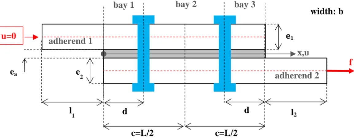
The interest in functionally graded adhesive (FGA) joints has been increasing in recent years [21-24]. FGAs offer the opportunity to optimize the strength of multi-material bonded joints by locally tailoring the adhesive properties and without modifying the design of the adherends to be joined. FGA joints involve a continuous variation of the adhesive properties along the overlap allowing for the homogenization of the stress distribution and load transfer. Manufacturing methods of FGA joints can be found in [24-26]. The objective of the present paper is then to assess the effect of adhesive graduation on the mechanical behaviour and static strength of HBB joints. The assessment is performed through a simplified 1D-bar stress model, able to quickly provide mechanical trends. It is exemplified on a balanced single-lap HBB joint made of thin aluminium plates and in-plane tensile loaded (Fig. 1), with two lines of identical fasteners and various types of adhesive graduation are employed. The present study could be regarded as an approach allowing for a simple and fast assessment of potential benefit in terms static strength only. The 1D-bar model for HBB joint with FGA is based on the macro-element technique [7, 22, 27-29]. The macro-element (ME) technique has been initially developed by the authors and co-workers for the simplified stress analysis of HBB joints with homogeneous adhesives (HA) [7, 22, 27-28] and successfully applied to the simplified stress analysis of FGA joints [29].
Fig. 1 Geometrical parametrization of the single-lap joint, boundary conditions and applied loads
f x,u c=L/2 c=L/2 e1 e 2 width: b ea u=0 l2 l 1 d d adherend 2 adherend 1
II.
Description of the 1D-bar model
A. Hypotheses
The following hypotheses are taken (i) the adherends are linear elastic materials simulated as bars, (ii) the adhesive layer is modelled by an infinite number of linear elastic shear springs linking both adherends, (iii) the adhesive layer thickness remains constant along the overlap, and (iv) the fasteners are modelled by linear elastic shear springs linking both adherends. It results then that (i) only longitudinal displacements and normal forces are considered in the adherends, (ii) all the adhesive stress components vanish except the in-plane shear which is constant in through the thickness and (iii) the fasteners transfer the loading by in-plane shearing deformation only. The graduation of the adhesive properties is represented by a variation of the shear adhesive modulus, termed Ga, as function of its abscissa x along the overlap. It is then indicated that the induced rotation of the overlap as well as of fasteners, due the eccentricity of the load paths are not taken into account in this paper. 1D-beam simplified stress analyses of HBB joints with HA or of bonded joints with FGA can be found in [22] and [29] respectively.
B. Modelling with the Macro-Element Technique
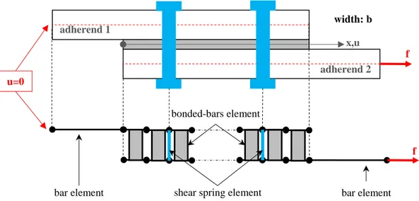
The ME technique is inspired by the Finite Element method and differs in the sense that the interpolation functions of MEs are not assumed. Indeed, they take the shape of solutions of the governing ordinary differential equations (ODEs) system, coming from the constitutive equations of materials and from the local equilibrium equations, related to the simplifying hypotheses. A direct consequence is only one ME is needed to simulate a full bonded overlap with a HA. Dedicated 4-nodes bonded-bars (BBa) and bonded-beams have been formulated. The main work consists in the formulation of the ME elementary stiffness matrix. The adherend located outside the overlap are modelled by bar elements, while the fasteners are modelled by shear spring elements. To take into account for the adhesive graduation, the overlap is regularly meshed with n_ME BBa elements, the length of which is then L/n_ME. A constant value of the adhesive shear modulus is assigned to each ME. It is taken equal to the actual value of the modulus graduation at the abscissa located at the middle of the ME. The actual graduation of the adhesive properties is then approximated by a stepped function. In this paper, a mesh density of 10 MEs per mm is chosen, which is sufficient to obtain accurate results as shown in [29]. Once the stiffness matrix of the complete structure is assembled from the elementary stiffness matrices and the boundary conditions are applied, the minimization of the potential energy provides the solution (Fig. 2). The distribution along the overlap of the adherend displacements and internal forces as well as the adhesive shear stress and the bolt load transfer rate are the
output of the analysis. A computer program is needed to obtain the solution. The scientific computing software SCILAB is used [30]. The SCILAB code is attached to this paper as supplement materials.
Fig. 2 Modelling of the single-lap HBB joint with FGA by using the macro-element technique
C. Elementary Stiffness Matrix Formulation
Even if the ME elementary stiffness matrix has already been described in details in [7, 22, 27-28], the main steps are provided for the comfort of the reader. The length of the ME is quoted . The local equilibrium of both adherends (Fig. 3a) provides the following equations:
𝑑𝑁𝑗
𝑏𝑑𝑥= (−1)
𝑗𝑇(𝑥), 𝑗 = 1,2 (1)
where b is the overlap width, Nj the normal force in the adherend j and T the adhesive shear stress. It refers to the local equilibrium employed by Volkersen [31].The constitutive equations for the adherends are such as:
𝑑𝑢𝑗 𝑑𝑥 =
𝑁𝑗
𝐴𝑗, 𝑗 = 1,2 (2)
where uj is the longitudinal displacement of the adherend j and Aj is the membrane stiffness of adherend j equal to ejbEj with ej the thickness of adherend j and Ej the Young’s modulus of the adherend j. The constitutive equation for the adhesive layer is given by:
𝑇 =𝐺𝑎
𝑒𝑎(𝑢2− 𝑢1) (3)
The elementary stiffness matrix of the BBa element, termed KBBa, represents for the linear relationships between the nodal forces and the displacements (Fig. 3b):
bar element shear spring element
f x,u width: b u=0 adherend 2 adherend 1 bar element f bonded-bars element
( −𝑁1(0) −𝑁2(0) 𝑁1(Δ) 𝑁2(Δ) ) = 𝐾𝐵𝐵𝑎 ( 𝑢1(0) 𝑢2(0) 𝑢1(Δ) 𝑢2(Δ)) (4)
From Eqs (1-3) a system of coupled of ODEs in u1 and u2 can be written and solved. The four integration constants are identified using the four nodal displacements. The normal forces N1 and N2 are then deduced from u1 and u2 with the constitutive equation in Eq. (2) as function of the nodal displacements. The nodal forces are finally then expressed as functions of the nodal displacements, leading to the closed-form expressions for the KBBa components, such as: 𝐾𝐵𝐵𝑎=1+𝜒1 𝐴 𝐴2 Δ ( 𝜂Δ tanh 𝜂Δ+ 1 𝜒𝐴 1 − 𝜂Δ tanh 𝜂Δ − 𝜂Δ sinh 𝜂Δ− 1 𝜒𝐴 𝜂Δ sinh 𝜂Δ− 1 1 −tanh 𝜂Δ𝜂Δ tanh 𝜂Δ𝜂Δ + 𝜒𝐴 sinh 𝜂Δ𝜂Δ − 1 −sinh 𝜂Δ𝜂Δ − 𝜒𝐴 −sinh 𝜂Δ𝜂Δ −𝜒1 𝐴 𝜂Δ sinh 𝜂Δ− 1 𝜂Δ tanh 𝜂Δ+ 1 𝜒𝐴 1 − 𝜂Δ tanh 𝜂Δ 𝜂Δ sinh 𝜂Δ− 1 − 𝜂Δ sinh 𝜂Δ− 𝜒𝐴 1 − 𝜂Δ tanh 𝜂Δ 𝜂Δ tanh 𝜂Δ+ 𝜒𝐴 ) (5) where: 𝜒𝐴=𝐴𝐴2 1 (6) 𝜂 = √𝐺𝑎 𝑒𝑎 𝑏 𝐴2(𝜒𝐴+ 1) (7)
The stiffness matrices of the bar elements and of the shear spring element are given by: 𝐾𝑏𝑎𝑟,𝑗= 𝐴𝑗 𝑙𝑗( 1 −1 −1 1 ) (8) 𝐾𝑠𝑝𝑟𝑖𝑛𝑔= 𝐶 ( 1−1 −11 ) (9) where lj is the adherend length outside the overlap and C the fastener stiffness.
b) a) u1() u 2() u1(0) u 2(0) -N 1(0) -N 2(0) N 1() N2() N1(x+dx) N1(x) T.bdx N 2(x+dx) N 2(x)
Fig. 3 a) Free body diagram of infinitesimal pieces included between x and x+dx of both adherends in the overlap region. Subscript 1 (2) refers to the upper (lower) adherend, b) Nodal forces and nodal displacements
on a BBa element
D. Particular Case of Balanced HBB Joints with Two Lines of Fasteners and with HA
In the case of balanced HBB joints with two lines of fastener with HA, it is possible to derive closed-form expressions for the bolt load transfer rate as well as the maximal adhesive shear stress. The presence of two lines of fasteners implies that there are three bonded bays (Fig. 1). On each bay i, an ODE in N2,i can be written from the governing equations Eqs. (1-3) and from the global equilibrium N1,i+N2,i=f in any abscissa x:
𝑑2𝑁2,𝑖
𝑑𝑥2 − 𝜂2𝑁2,𝑖= −𝜂2 𝜒1+𝜒𝐴𝐴𝑓, 𝑖 = 1. .3 (10) The solution of this previous ODE takes the following shape:
𝑁2,𝑖= 𝑐𝑖𝑒−𝜂𝑥+ 𝑘𝑖𝑒𝜂𝑥+1+𝜒𝜒𝐴
𝐴𝑓, , 𝑖 = 1. .3 (11)
where ci and ki are integration constants. From the local equilibrium equation Eq. (1), the expression for the shear stress on each bay i is deduced:
𝑇𝑖=𝜂𝑏(𝑘𝑖𝑒𝜂𝑥− 𝑐𝑖𝑒−𝜂𝑥), 𝑖 = 1. .3 (12) Six boundary constants have to be written to determine the six integration constants. The normal force of the adherend 2 in x=0 is equal to zero (N2,1(x=0)=0), while it value in x=L is equal to f (N2,3(x=0)=f). The continuity of the shear stress at each fastener provides two additional equations: T1(x=d)=T2(x=d) and T1(x=L-d)=T2(x=L-d). Both last equations correspond to the load transfer by both fasteners: N2,2(x=d)=N2,1(x=d)+1f and N2,2 (x=L-d)=N2,3(x=L-d)+2f. The bolt load transfer rates i are written as functions of the relative displacements of adherends and then of the adhesive shear stress at fastener location:
𝜏1𝑓 = 𝐶(𝑢2(𝑑) − 𝑢1(𝑑)) = 𝐶𝐺𝑒𝑎
𝑎𝑇1(𝑑) (13)
𝜏2𝑓 = 𝐶(𝑢2(𝐿 − 𝑑) − 𝑢1(𝐿 − 𝑑)) = 𝐶 𝑒𝑎
𝐺𝑎𝑇2(𝐿 − 𝑑) (14)
( 1 1 0 0 0 0 𝑒−𝜂𝑑 −𝑒𝜂𝑑 −𝑒−𝜂𝑑 𝑒𝜂𝑑 0 0 𝑞𝑒−𝜂𝑑 𝑟𝑒𝜂𝑑 −𝑒−𝜂𝑑 −𝑒𝜂𝑑 0 0 0 0 𝑒−𝜂(𝐿−𝑑) −𝑒𝜂(𝐿−𝑑) −𝑒−𝜂(𝐿−𝑑) 𝑒𝜂(𝐿−𝑑) 0 0 𝑞𝑒−𝜂(𝐿−𝑑) 𝑟𝑒𝜂(𝐿−𝑑) −𝑒−𝜂(𝐿−𝑑) −𝑒𝜂(𝐿−𝑑) 0 0 0 0 𝑒−𝜂𝐿 𝑒𝜂𝐿 )( 𝑐1 𝑘1 𝑐2 𝑘2 𝑐3 𝑘3) = ( − 𝜒𝐴 1+𝜒𝐴𝑓 0 0 0 0 1 1+𝜒𝐴𝑓 ) (15) where: 𝑞 = 1 − 𝐶𝑒𝑎 𝐺𝑎 𝜂 𝑏 (16) 𝑟 = 1 + 𝐶𝑒𝑎 𝐺𝑎 𝜂 𝑏 (17)
Since the joint is assumed to be balanced, A=1 and both fasteners carry the same load. From Eqs. (13-14) and from the continuity of adhesive shear stress, it comes then T1(d)=T2(d)=T2(L-d)=T3(L-d), so that the linear system is reduced to the following one:
( 1 1 0 0 𝑒−𝜂𝑑 −𝑒𝜂𝑑 −𝑒−𝜂𝑑 𝑒𝜂𝑑 𝑞𝑒−𝜂𝑑 𝑟𝑒𝜂𝑑 −𝑒−𝜂𝑑 𝑒𝜂𝑑 𝑒−𝜂𝑑 −𝑒𝜂𝑑 𝑒−𝜂(𝐿−𝑑) 𝑒𝜂(𝐿−𝑑) ) ( 𝑐1 𝑘1 𝑐2 𝑘2 ) = ( −𝑓2 0 0 0 ) (18)
After linear combinations, the system can be reduced to: (𝑞̅𝑒1−𝜂𝑑 𝑟̅𝑒1𝜂𝑑) (𝑘𝑐1 1) = (− 𝑓 2 0 ) ⇒ ( 𝑐1 𝑘1) = 1 𝑟̅𝑒𝜂𝑑−𝑞̅𝑒−𝜂𝑑( 𝑟̅𝑒 𝜂𝑑 −1 −𝑞̅𝑒−𝜂𝑑 1 ) (− 𝑓 2 0 ) (19) where: 𝑞̅ = 1 − cosh 𝜂(𝐿 − 2𝑑) + 𝑞 sinh 𝜂(𝐿 − 2𝑑) (20) 𝑟̅ = −1 + cosh 𝜂(𝐿 − 2𝑑) − 𝑟 sinh 𝜂(𝐿 − 2𝑑) (21)
The closed-form expressions for the bolt transfer rates are then deduced from Eq. (13) and Eqs. (20-21) such as: 𝜏1= 𝐶𝑒𝐺𝑎 𝑎 𝜂 𝑏(𝑘1𝑒 𝜂𝑑− 𝑐 1𝑒−𝜂𝑑)1𝑓=12𝐶𝐺𝑒𝑎 𝑎 𝜂 𝑏 𝑟̅+𝑞̅ 𝑟̅𝑒𝜂𝑑−𝑞̅𝑒−𝜂𝑑= 𝜏2 (22)
As the maximal shear stress is located at both overlap ends in the case of HA [7, 22, 27-29], the closed-form solution for the maximal stress Tmax is:
𝑇𝑚𝑎𝑥 = 𝑇1(𝑥 = 0) =𝜂𝑏(𝑘1− 𝑐1) =12𝑟̅𝑒
𝜂𝑑+𝑞̅𝑒−𝜂𝑑
𝑟̅𝑒𝜂𝑑−𝑞̅𝑒−𝜂𝑑𝜂 𝑓
𝑏 (23)
III.
Numerical Testing
The example of a balanced single-lap HBB joint made of thin aluminium and two identical fasteners is chosen. It is indicated that, in terms of modelling, the fasteners could be different from each other. The geometry is then built from the diameter of the fastener shank equal to 4.8 mm. The geometrical and mechanical parameters are provided in Table 1. The fastener stiffness C chosen has the same order of magnitude obtained using the Tate and Rosenfeld [32] formula for a titanium fastener.
Table 1 Numerical and geometical parameters
b (mm) C (N.mm-1) d (mm) E1=E2 (MPa) ea (mm) ej (mm) f (kN) L (mm) l1=l2 (mm) 24 30000 12 70000 0.2 1.6 5 48 48
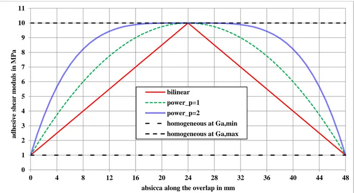
In this paper, the adhesive shear modulus is assumed to follow three different graduation laws: (i) a bilinear law (Eq. (26)), (ii) a power law at p=1 (Eq. (25)) and (iii) a power law at p=2 (Eq. (25)):
𝐺𝑎(𝑥) = 𝐺𝑎,𝑚𝑎𝑥(𝑥) − (𝐺𝑎,𝑚𝑎𝑥(𝑥) − 𝐺𝑎,𝑚𝑖𝑛(𝑥)) |𝑥𝑐− 1| (24) 𝐺𝑎(𝑥) = 𝐺𝑎,𝑚𝑎𝑥(𝑥) − (𝐺𝑎,𝑚𝑎𝑥(𝑥) − 𝐺𝑎,𝑚𝑖𝑛(𝑥)) (𝑥𝑐− 1)
2𝑝
(25)
These graduation laws are symmetrical with respect to the middle of the overlap, where the maximal adhesive shear modulus Ga,max is reached. The minimal adhesive shear modulus Ga,min is obtained at both overlap ends. Both power laws show a horizontal slope at the middle of the overlap. These graduation laws are then fully defined from Ga,max and Ga,min, and from a parameter p modifying the shape. In this paper, the minimal adhesive shear modulus is fixed at Ga_min=1 MPa. An illustration of these graduation laws along the overlap can be found in Fig. 4 for the particular case where Ga,min=1 MPa and Ga,max=10 MPa.
Fig. 4 Adhesive shear modulus graduation for the particular case of Ga,min=1 MPa and Ga,max=10 MPa
B. Load Sharing
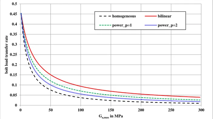
Firstly, the load sharing between the fasteners and the adhesive layer is investigated. The bolt load transfer rate at each fastener is then computed as a function of the adhesive shear modulus Ga,max for HA and FGAs (Fig. 5). For HA, it means that Ga=Ga,max. The selected range of variation Ga,max is 1 MPa to 300 MPa. For HA, the results come from the formulae in Eq. (22) whereas for FGAs the ME model is used. It is shown that a similar evolution of the bolt load transfer as function of Ga,max is obtained for HA and FGAs. The more the adhesive shear modulus is elevated, the less the fasteners transfer load. As for the HBB joint with HA, the HBB joint with the considered FGAs tends to behave like a pure bonded joint for higher Ga,max and like a pure bolted joint for lower Ga,max. Compared to the HBB joint with HA at a given Ga,max, the HBB joint with FGAs at that Ga,max are characterized by a higher transfer load by the fasteners. The range of Ga,max for which the load is shared between the adhesive layer and the fasteners is restricted. In other words, the adhesive layer can be regarded as a third load path in addition to both load paths at fastener location is confined to low values of Ga,max and the FGAs tend to enlarge the range of Ga,max. For the remainder of the paper Ga,max is fixed at 10 MPa, or ten times Ga,min, which is an assumed level of maximal reinforcement. The concept of effective modulus presented by Adams and Mallick [33] allows for the use of linear
0 1 2 3 4 5 6 7 8 9 10 11 0 4 8 12 16 20 24 28 32 36 40 44 48 a d h esiv e sh ea r m o d u ls in M Pa
absicca along the overlap in mm bilinear
power_p=1 power_p=2
homogeneous at Ga,min homogeneous at Ga,max
elastic analyses to take into account adhesive nonlinear behaviour. It is based on an equivalency of adhesive shear strain energy. The range 1 to 10 MPa corresponds then to highly ductile adhesives in the previous framework or to structural sealants [14, 34].
Fig. 5 Bolt load transfer rate as function of Ga,max
C. Adhesive Behavior Under Loading
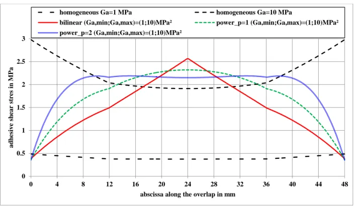
The adhesive shear stress distribution along the overlap for HA and FGAs are provided in Fig. 6. For HA, the results comes from the formulae in Eq. (23) is used whereas for FGAs the ME model is used. If both overlap ends are the location for the maximal adhesive shear stress for the HBB joint with HA, they are the location of the minimal adhesive shear stress for the HBB joint with FGA. The maximal adhesive shear stress is located at the middle of the overlap for the bilinear law and power law at p=1. It is located around the fastener location for the power law at p=2. The use of FGAs allow for this atypical shear stress distribution along the overlap [35, 29]. Moreover, the fastener location (x=12 mm and x=36 mm) are points of discontinuity of the first derivative of the adhesive shear stress distribution for the HBB joint with HA and FGAs, due to the discrete load transfer mode at fasteners [7, 25-26]. 0 0.05 0.1 0.15 0.2 0.25 0.3 0.35 0.4 0.45 0.5 0 50 100 150 200 250 300 b o lt lo a d tr a n sfe r ra te Ga,max in MPa homogeneous bilinear power_p=1 power_p=2
Fig. 6 Adhesive shear stress distribution along the overlap
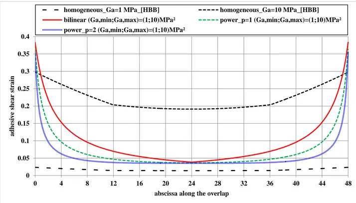
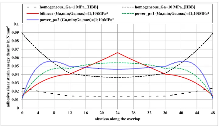
For the geometrical and mechanical parameters selected in this paper, the HBB joint with FGAs exhibit maximal adhesive shear stress in a region of the overlap where the horizontal relative difference of longitudinal adherend – then related to the adhesive shear strain – is minimal as shown in Fig. 7. It is noticed that the adhesive stresses and strains at both overlap ends in the FGA configurations appears as more or less independent on the considered graduation. The effects of the adhesive shear modulus graduation appears on the slope of the adhesive shear stress and strain distributions along the overlap as well as on the value and the position on the overlap of the maximal adhesive stresses. This behavior has already been observed by Stein et al. [35] for the case of pure bonded joints. Besides, for ductile adhesives, it is well established that the adhesive stress is not the suitable strength criteria [33, 35-37]. The adhesive shear strain and strain energy density distributions along the overlap for HA is then provided in Fig. 8. The adhesive shear strain energy density is defined from the adhesive shear strain and stress as it follows:
𝑈(𝑥) =1 2𝑒𝑎[ 𝑢2(𝑥) − 𝑢1(𝑥) 𝑒𝑎 ] 𝐺𝑎(𝑥) [ 𝑢2(𝑥) − 𝑢1(𝑥) 𝑒𝑎 ] = 1 2 𝐺𝑎(𝑥) 𝑒𝑎 [𝑢2(𝑥) − 𝑢1(𝑥)] 2 (26) 0 0.5 1 1.5 2 2.5 3 0 4 8 12 16 20 24 28 32 36 40 44 48 a d h esiv e sh ea r str es in M Pa
abscissa along the overlap in mm
homogeneous Ga=1 MPa homogeneous Ga=10 MPa
bilinear (Ga,min;Ga,max)=(1;10)MPa² power_p=1 (Ga,min;Ga,max)=(1;10)MPa²
It is then observed that the distribution along the overlap adhesive shear strain energy density follows the same evolution as the distribution along the overlap of the adhesive shear stress.
Fig. 7 Adhesive shear strain distribution along the overlap
0 0.05 0.1 0.15 0.2 0.25 0.3 0.35 0.4 0 4 8 12 16 20 24 28 32 36 40 44 48 a d h esiv e sh ea r str a in
abscissa along the overlap
homogeneous_Ga=1 MPa_[HBB] homogeneous_Ga=10 MPa_[HBB]
bilinear (Ga,min;Ga,max)=(1;10)MPa² power_p=1 (Ga,min;Ga,max)=(1;10)MPa²
Fig. 8 Adhesive shear strain energy density distribution along the overlap
IV.
Potential Strength Benefit of HBB joint
A. Compared to Pure Bonded and HBB Joint with HA
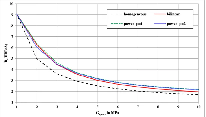
In order to assess the potential benefit in static strength of the HBB joint with HA and FGAs compared to the pure bonded joint with HA – termed Bs(HBB/A) – it is assumed that the fastener behaviour is not affected during the loading. The potential benefit Bs(HBB/A) is computed from the square root of the ratio between the maximal adhesive shear strain energy density of the pure bonded joint with HA to the maximal adhesive shear strain energy density of the pure bonded joint with HA or FGAs at fixed Ga,max. The potential benefit Bs(HBB/A) as function of Ga,max, varying between 1 MPa and 10 MPa, is provided in Fig. 9. It is shown that, for the HBB joint with HA and FGA, the potential benefit increases with decreasing Ga,max – related to an increase of the load transferred by the bolts. The use of FGAs instead of HA leads to a significant increase in the benefit of around 20% depending on Ga,max and the graduation law. The potential benefit Bs(HBB/A) does not seem to significantly vary with the graduation law, even if power law with p=1 and p=2 leads to higher benefit at higher Ga,max than the bilinear graduation law. It is related to the fact that at fixed Ga,max, the load carried by the fastener is higher with HA than
0 0.01 0.02 0.03 0.04 0.05 0.06 0.07 0.08 0.09 0.1 0 4 8 12 16 20 24 28 32 36 40 44 48 a d h esiv e sh ea r str a in e n er g y d en sity in N.m m -1
abscissa along the overlap
homogeneous_Ga=1 MPa_[HBB] homogeneous_Ga=10 MPa_[HBB]
bilinear (Ga,min;Ga,max)=(1;10)MPa² power_p=1 (Ga,min;Ga,max)=(1;10)MPa²
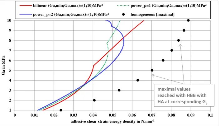
with FGAs. Nevertheless, it has been shown that for the HBB joint with FGAs the adhesive shear strain energy density could vary the overlap abscissa and then with the actual value of Ga, so that a potential benefit based on the maximal strain energy density could not be suitable. The adhesive shear strain energy density of the HBB joint with FGAs at Ga,max=10 MPa is then drawn as function of the actual value of the adhesive shear modulus along the overlap and compared to the maximal adhesive shear strain energy density of the HBB joint with HA in Fig. 10, which is taken as reference. It is shown that the three graduation laws lead to adhesive shear strain energy density significantly lower than the one of the HBB joint with the HA at any Ga. As a result, compared to the HBB joint with HA, the HBB joint with FGAs have a potential benefit higher than one, the value of which depends on Ga,max and the graduation law.
Fig. 9 Potential benefit Bs(HBB/A) in static strength of the HBB joint with HA and FGAs compared to the
pure bonded joint with HA.
1 2 3 4 5 6 7 8 9 10 1 2 3 4 5 6 7 8 9 10 Bs (H B B /A) Ga,max in MPa homogeneous bilinear power_p=1 power_p=2
Fig. 10 Adhesive shear strain energy density associated to the actual adhesive shear modulus
B. Compared to Pure Bolted
In order to assess the potential benefit in static strength of the HBB joint with HA and FGAs compared to the pure bolted joint – termed Bs(HBB/F) – it is assumed that the adhesive layer behaviour is not affected during the loading. The three main failure static modes of metallic bolted joints are (i) the net section failure, (ii) the bearing failure and the fastener shearing failure [37]. The net section failure depends on the passing load in the plate at the fastener location and the bearing and fastener shearing failure depends on the load carried by the fastener. As a result, the bolt transfer rate is a suitable parameter for the basis of a potential benefit assessment. The potential benefit Bs(HBB/F) is then computed as the ratio between 0.5 and the actual bolt load transfer and is given as function of Ga,max in Fig. 11. As expected from Fig. 4, the HBB joint with HA provides the maximal potential benefit Bs(HBB/F). As for the HBB joint with HA, the potential benefit Bs(HBB/F) for the HBB joint with FGAs tends to linearly increase with increasing Ga,max. Among the three graduation law the power law at p=2 leads to higher Bs(HBB/F). Besides, the potential benefit Bs(HBB/F+) in static strength of the HBB joint with two lines of fasteners and with HA and FGAs compared to a pure bolted joints with three lines of fasteners is assessed. The objective is to
1 2 3 4 5 6 7 8 9 10 0 0.01 0.02 0.03 0.04 0.05 0.06 0.07 0.08 0.09 0.1 G a in M Pa
adhesive shear strain energy density in N.mm-1
bilinear (Ga,min;Ga,max)=(1;10)MPa² power_p=1 (Ga,min;Ga,max)=(1;10)MPa²
power_p=2 (Ga,min;Ga,max)=(1;10)MPa² homogeneous [maximal]
maximal values
reached with HBB with
HA at corresponding G
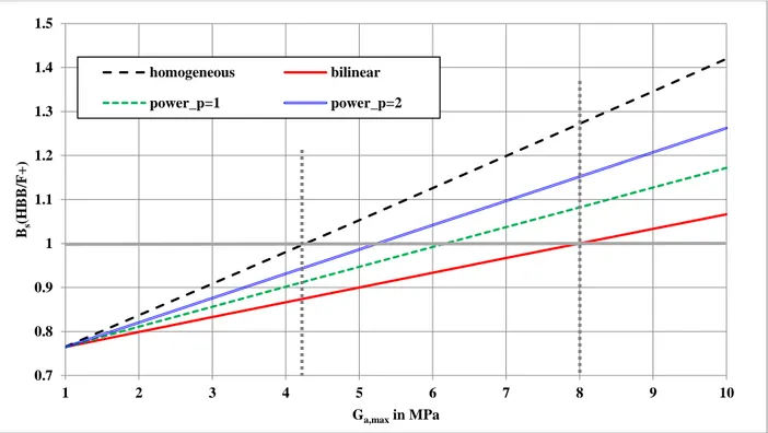
aevaluate the level of Ga,max allowing for the removal of one third of fastener pitches. The maximal bolt load transfer rate is located at external fastener lines and is equal to 34.70%, by using the ME model with Ga=1E-8 MPa. To compute Bs(HBB/F+), this last bolt load transfer rate is taken as the reference bolt load transfer rate instead of 0.5 in Bs(HBB/F). It is given as a function of Ga,max in Fig. 12. It is shown that for Ga,max lightly higher than 4 MPa, a HBB joint with HA and two lines of fasteners has potentially has the same static strength as the pure bolted joint with three lines of fasteners. For HBB with FGAs, Ga,max has to be taken equal from 5 MPa to 7 MPa, depending on the graduation law. Besides, following the Niu uni-axial analysis [37], the fatigue strength of bolted joints is related to the stress concentration factor, computed as the ratio of the peak stress at fastener hole with the remote applied stress. The peak stress is computed from the by-passed load and the transferred load so that the stress concentration factor appears a linearly increasing function of the bolt load transfer rate. As a result, assuming that the adhesive behaviour is not degraded under fatigue loaded, it could be possible, with the previous simple analysis, to simply assess the potential benefit in terms of fatigue strength of HBB joints with HA or FGA. It is indicated that Lim et al. [21] has recently shown that, in the case of HBB joint with a flexible epoxy adhesive, the load carried by the fastening system increases under cyclic loading up to a constant value, allowing for a load with the adhesive layer.
1 1.2 1.4 1.6 1.8 2 2.2 1 2 3 4 5 6 7 8 9 10 Bs (H B B /F ) Ga,max in MPa homogeneous bilinear power_p=1 power_p=2
Fig. 11 Potential benefit Bs(HBB/F) in static strength of the HBB joint with HA and FGAs compared to
the pure bolted joint
Fig. 12 Potential benefit Bs(HBB/F+) in static strength of the HBB joint with HA and FGAs compared to
the pure bolted joint with 3 lines of fastener
C. Remarks and Limits
From the previous analysis, it is possible to represent for the potential benefit Bs(HBB/F) as a function of Bs(HBB/A) for HBBA with HA and FGAs such as Ga,min=1 MPa and Ga,max varying between 1 MPa and 10 MPa (Fig. 13). It allows for a simple representation of the potential design choices as functions of prescribed strength objectives expressed in terms of pure bonded or pure bolted joint solutions. For the HBB joint under consideration, the power graduation law at p=2 seems to be the most efficient among the graduation laws tested.
The single-lap configuration leads to the existence of adhesive peel stress due to the eccentricity of the load path. That peel stress is mainly driven the failure of adhesive layer at both overlap ends, before reaching its maximal adhesive shear strain energy [38]. Several design solutions have been published to reduce the adhesive peel stress [39]. The tapering of adherends at overlap ends, which allows for a progressive increase of the neutral line lag, is
0.7 0.8 0.9 1 1.1 1.2 1.3 1.4 1.5 1 2 3 4 5 6 7 8 9 10 Bs (H B B /F + ) Ga,max in MPa homogeneous bilinear power_p=1 power_p=2
one solution for example [40-41]. When applicable to the design requirements, these solutions could promote the failure of the adhesive layer used in the HBB joints by shearing instead of peeling. Besides, the presented analysis of potential does not take into account for the progressive degradation of adhesive properties. The potential increase of the maximal applied tensile load sustainable, compared to the pure bonded configuration, cannot be captured [8, 22]. This paper presents only a potential strength benefit which remains to be confirmed in terms of strength benefit, as function of the actual adhesive material behaviour laws and associated relevant strength criteria.
Fig. 13 Potential benefit Bs(HBB/F) as function of the potential benefit Bs(HBB/A) for HBB with HA and
FGAs such as Ga,min=1 MPa and Ga,max varying between 1 MPa and 10 MPa
V.
Conclusion
In this paper, the potential static strength benefit of HBB joints with functionally graded adhesives (FGAs) is assessed, through a shear lag type simplified stress analysis applied to a particular single-lap joint, made of two thin identical aluminum plates and with two lines of fasteners. Three particular symmetrical graduation laws, defined by the minimum adhesive shear modulus Ga,min chosen equal to 1 MPa and by the maximal one Ga,max, are tested. The following conclusions could be made. Firstly, compared to a homogeneous adhesive (HA) at a maximal shear
1 1.2 1.4 1.6 1.8 2 2.2 1 2 3 4 5 6 7 8 9 10 B s(H B B /F ) Bs(HBB/A) homogeneous bilinear power_p=1 power_p=2
modulus Ga,max, the FGAs allows for a better load sharing between the adhesive layer and the fasteners on a large range of adhesive modulus. Secondly, the HBB joint with HA offers then a higher potential strength benefit for the fastening part and lower potential strength benefit for the adhesive layer than FGAs. Thirdly, for the mechanical and geometrical configuration tested, the most attractive graduation law is the power law at p=2. In a similar way, this analysis could be performed in the 1D-beam framework instead of 1D-bar analysis, possibly involving adhesive and/or fastener nonlinear material law under various loading, using the ME technique. The models presented can be potentially used to optimize the adhesive graduation law as function of the geometrical and mechanical parameters of the joints to reach fixed potential strength benefits. This work focuses only on the potential mechanical strength and does not take into account for the certification and manufacturing requirements. Finally, an interesting application HBB joining of metallic sheets with HA and FGAs could be the reduction of the load transferred by the fasteners to improve the fatigue life compared to the pure bolted joint, while ensuring the static strength under extreme loads, if the adhesive is able to sustain the applied load over the time.
Appendix
This appendix aims at providing elements of validation of the simplified stress analysis presented in this paper. Firstly, the 1D-bar simplified stress analysis is based on two well-known models: (i) the electrical analogy model for the bolted part by Ross (1947) [42] and (ii) the shear-lag model for the bonded part with HA by Volkersen (1938) [31]. In other words, the 1D-bar model for HBB joints with HA is founded on the same hypotheses as those used by Ross and by Volkersen, so that it consists in adding the punctual shear springs by Ross simulating the fasteners within the shear lag model by Volkersen. The ME technique allows for the resolution of the system of ODE’s involved. The resolution by the ME technique hase already been compared with a more classical resolution scheme based on the direct integration of ODEs [7, 27]. It was shown that both resolution schemes provide the same results for the same set of modelling hypotheses. In order to fit the experimental results as well as the FE predictions, the fastener stiffnesses are tuned as shown in [7]. Moreover, the 1D-bar model for HBB joints was enriched to take in to account for elasto-plastic adhesive material behavior [7, 27]. This enriched model was retaken by Bois et al. [43] and assessed with success against predictions from finite element (FE) models. The same conclusions on the configuration of pure bonded joints with HA can be found in a paper published by the authors of the present paper and co-workers [44]. When dealing with the FGA, the 1D-bar HBB model remains founded on both previous
well-known models for pure bonded joints and pure bolted joints. In order to take into account for the graduation of adhesive properties, the ME technique is applied involving a mesh strategy. As a result, the 1D-bar model for HBB joints with FGA consists again in adding the punctual shear springs by Ross simulating the fasteners within the shear lag model by Volkersen. In [29], it is shown that, for the 1D-model for bonded joints with FGA, the resolution scheme using the ME technique provides the same results as the resolution scheme based on Taylor expansion power series by Stein et al. [35], who made available their code as a supplementary materials. A comparison of predictions in terms of the adhesive shear stress distributions along the overlap by the Stein et al. 1D-bar code and the present 1D-bar code is provided in Fig. 14. The material and geometrical parameters described in Table 1 are chosen as well as a power law graduation with p=1 and Ga,min =1 MPa and Ga,max=10 MPa. Moreover the 1D-ME HBB code is forced to work without any fasteners by setting the fastener stiffnesses C equal to 0 N.mm-1. The
predictions are in very close agreement.
Fig. 14 Comparison of predictions in terms of adhesive shear stress distributions by Stein et al. code and the present 1D-bar ME HBB code with a fastener stiffness C=0 N.mm-1
The authors of the present paper and co-workers have published a recent and detailed paper dedicated to the validation of 1D-bar and 1D-beam simplified stress analyses involving the ME technique as the resolution scheme for the single-lap bonded joints with FGA under combined thermal and mechanical loadings [45]. The validation was performed against 1D-bar or 1D-beam FE models and 3D FE models for which the adhesive layer is modelled
0 1 2 3 4 5 6 0 4 8 12 16 20 24 28 32 36 40 44 48 a d h esiv e sh ea r str ess in M Pa
abscissa along the overlap in mm Stein et al. code present code
either by brick elements or by interface elements. The 1D FE models are developed to be as closest as possible of the hypotheses of the ME models. It means that the 1D-bar FE model is developed with bar elements for the adherends and shear springs for the adhesive layer. After convergence studies, it is shown that the 1D-bar ME model leads to the same results the 1D-bar FE model. The same conclusion is obtained when the 1D-beam model is compared to the 1D-FE model. The assessment of the 1D-beam model against 3D FE model leads to a maximal absolute deviation of 17.49% of adhesive peak peel stress (7.88% for the adhesive peak shear stress), which is related to the approximation of the geometrical nonlinearity used in the 1D-beam model.
Funding Sources
This work has not received any specific grant.
References
[1] Hart-Smith, L.J., “Design methodology for bonded-bolted composite joints,” AFWAL-TR-81-3154, 1982, Douglas Aircraft Company, Long Beach, California.
[2] Higgins, A., “Adhesive bonding of aircraft structures,” International Journal of Adhesion and Adhesives, Vol. 20, 2000, pp. 367-376.
doi: 10.1016/S0143-7496(00)00006-3
[3] Hart-Smith, L.J., “Adhesive bonding of aircraft primary structures,” SAE Transactions, Vol. 89, Section 4: 801147-801431, 1980, pp. 3718-3732.
doi: 10.4271/801209
[4] Dechwayukul, Rubin, C.A., Hahn, G.T., “Analysis of the effects of thin sealant layers in aircraft structural joints,” AIAA
Journal, Vol. 41, No. 11, 1983, pp. 2216-2228.
doi: 10.2514/2.6814
[5] Hart-Smith, L.J., “Bonded-bolted composite joints, ” Journal of Aircraft, Vol. 22, No. 11, 1985, pp. 993-1000. doi: 10.2514/3.45237
[6] Hartman, A., “Fatigue tests on single-lap joints in clad 2024-T3 aluminium alloy manufactured by a combination of riveting and adhesive bonding,” NLR TN M2170, 1966, Amsterdam, The Netherlands.
[7] Paroissien, E., “Contribution aux Assemblages Hybrides (Boulonnés/Collés) – Application aux Jonctions Aéronautiques,” PhD Dissertation, Université de Toulouse III, Institut de Génie Mécanique, Toulouse, France, 2006. [on line: http://oatao.univ-toulouse.fr/17642/].
[8] Kelly, G., “Quasi-static strength and fatigue life of hybrid (bonded/bolted) composite single-lap joints,” Composite
Structures, Vol. 72, 2006, pp. 119-129.
doi: 10.1016/j.compstruct.2004.11.002
[9] Kweon, J.K., Jung, J.W., Kim, T.H., Choi, J.H., and Kim, D.H., “Failure of carbon composite-to-aluminium joints with combined fastening and adhesive bonding,” Composite Structures, Vol. 75, 2006, pp. 192-198.
doi: 10.1016/j.compstruct.2006.04.013
[10] Choi, J.I., Hasheminia, S.M., Chun, H.J., and Park, J.C., “Experimental study on failure mechanism of hybrid composite joints with different adhesives,” Fibers and Polymers, Vol. 18, pp. 569-574.
doi: 10.1007/s12221-017-1148-z
[11] Imanaka, M., Haraga, K., and Nishikawa, T., “Fatigue Strength of Adhesive/Rivet Combined Lap Joints,” Journal of
Adhesion, 49, 1995, pp. 197-209.
doi: 10.1080/00218469508014356
[12] Stewart, M.L., “An experimental investigation of composite bonded and/or bolted repairs using single lap joint designs,” AIAA Paper 1997-1339, 1997.
doi: 10.2514/6.1997-1339
[13] Fu, M., and Mallick, P.K., “Fatigue of hybrid (adhesive/bolted) joints in SRIM composites,” International Journal of
Adhesion and Adhesives, Vol. 21, 2001, pp. 145-159.
doi: 10.1016/S0143-7496(00)00047-6
[14] Hoang-Ngoc, C.T., and Paroissien, E., “Simulation of Single-Lap Bonded and Hybrid (Bolted/Bonded) Joints with Flexible Adhesive,” International Journal of Adhesion and Adhesives, Vol. 30, No. 3, 2010, pp.117-129.
doi: 10.1016/j.ijadhadh.2009.12.002
[15] Sadowski, T., Golewski, P., and Zarzeka-Raczkowska, E., “Damage and failure processes of hybrid joints: adhesive bonded aluminium plates reinforced by rivets,” Computational Materials Science. Vol. 50, 2011, pp. 1256-1262.
doi:10.1016/j.commatsci.2010.06.022
[16] Moroni, F., Pirondi, A., and Kleiner, F., “Experimental analysis and comparison of the strength of simple and hybrid structural joints,” International Journal of Adhesion and Adhesives, Vol. 30, 2010, pp. 367-379.
doi: 10.1016/j.ijadhadh.2010.01.005
[17] Esmaeili, F., Chakherlou, T.N., and Zehsaz, M., “Investigation of bolt clamping force on the fatigue life of double lap simple bolted and hybrid (bolted/bonded) joints via experimental and numerical analysis,” Engineering Failure Analysis, Vol. 45, 2014, pp. 406-420.
[18] Bodjona, K., Raju, K., Lim, G.H., and Lessard, L., “Load sharing in single-lap bonded/bolted composite joints. Part I: Model development and validation,” Composite Structures, Vol. 129, 2015, pp. 268-275.
doi: 10.1016/j.compstruct.2015.04.040
[19] Bodjona, K. and Lessard, L., “Hybrid Bonded-fastened Joints and their Application in Composite Structures: A general review,” Journal of Reinforced Plastics and Composites, Vol. 35, No. 9, 2016, pp.764-781.
doi: 10.1177/0731684415627296
[20] Lopez-Cruz, P., Laliberté, J., and Lessard, L., “Investigation of bolted/bonded composite joint behaviour using design of experiments,” Composite Structures, Vol. 170, 2017, pp.192-201.
doi: 10.1016/j.compstruct.2017.02.084
[21] Lim, G.H., Bodjona, K., Raju, K., Romanov, V., Fielding, S. and Lessard, L., “Evolution of mechanical properties of flexible epoxy adhesives under cyclic loading and its effects on composite hybrid bolted/bonded joint design”, Composite Structures, Vol. 189, 2018, pp. 54-60.
doi: 10.1016/j.compstruct.2018.01.049
[22] Paroissien, E., Lachaud, F., Da Veiga, A., and Barrière, P., “Simplified stress analysis of hybrid (bolted/bonded) joints,”
International Journal of Adhesion and Adhesives, Vol. 77, 2017, pp. 183-197.
doi : 10.1016/j.ijadhadh.2017.05.003
[23] Kawasaki, S, Nakajima, G, Haraga, K, and Sato, C, “Functionally Graded Adhesive Joints Bonded by Honeymoon Adhesion Using Two Types of Second Generation Acrylic Adhesives of Two Components,” Journal of Adhesion, Vol. 92, No. 7-9, 2016, pp. 517-534.
doi: 10.1080/00218464.2015.1113525
[24] Durodola, J.F., “Functionally graded adhesive joints – A review and prospects,” International Journal of Adhesion and
Adhesives, Vol. 76, 2017, pp. 83-89.
doi: 10.1016/j.ijadhadh.2017.02.008
[25] Carbas R.J.C., da Silva L.F.M., Critchlow, G.W., “Adhesively bonded functionally graded joints by induction heating,”
International Journal of Adhesion and Adhesives , Vol. 48, 2014, pp. 110–118.
doi: 10.1016/j.ijadhadh.2013.09.045
[26] Carbas R.J.C., da Silva L.F.M., Andrès, L.F.S., “Functionally graded adhesive joints by graded mixing of nanoparticles,”
International Journal of Adhesion and Adhesives , Vol. 76, 2014, pp. 30–37.
[27] Paroissien, E., Sartor, M., and Huet, J., “Hybrid (bolted/bonded) joints applied to aeronautic parts: Analytical one-dimensional models of a single-lap joint,” In: Advanced in Integrated Design and Manufacturing in Mechanical Engineering II, S. Tichkiewitch, M. Tollenaere, and P. Ray (Eds.), 2007, pp. 95-110, Springer, Dordrecht, The Netherlands.
doi: 10.1007/978-1-4020-6761-7_7
[28] Paroissien, E., Sartor, M., Huet, J., and Lachaud, F., “Analytical two-dimensional model of a hybrid (bolted/bonded) single-lap joint,” Journal of Aircraft, Vol. 44, 2007, pp. 573-582.
doi : 10.2514/1.24452
[29] Paroissien, E., da Silva, L.F.M., and Lachaud, F., “Simplified stress analysis of functionally graded single-lap joints subjected to combined thermal and mechanical loads,” Composite Structures, 203, 2018, pp. 85-100.
doi: 10.1016/j.compstruct.2018.07.015
[30] SCILAB, Ver. 6.0.0-beta-2, Scilab Enterprise, ESI Group, Orsay, FR, 2016.
[31] Volkersen, O., “Die Nietkraftverteilung in Zugbeanspruchten Nietverbindungen mit konstanten Laschenquerschnitten,”
Luftfahrforschung, Vol. 15, No. 24, 1938, pp. 41-47.
[32] Tate, M.B., and Rosenfeld, S.J., “Preliminary investigation of the loads carried by individual bolts in bolted joints,” NACA TN-1051, 1946, Langley Field, VA.
[33] Adams, R.D., and Mallick, V., “The effect of temperature on the strength of adhesively-bonded composite-aluminium joints,” The Journal of Adhesion, Vol. 43, 1993, pp. 17-33.
doi: 10.1080/00218469308026585
[34] Ramière, J.F.., Briançon, C., Chéret, F., Jeandrau, J.P., Leroy, M., Renard, J., and Thionnet, A., “Jonctions hybrides boulonnées-collées. Application aux cas des structures d'avions,” Revue des Composites et des Matériaux Avancés, Vol. 20, No. 2, 2010, pp. 215-232.
doi: 10.3166/rcma.20.215-232
[35] Stein, N., Felger, J., and Becker, W., “Analytical models for functionally graded adhesive joints: A comparative study,”
International Journal of Adhesion and Adhesives, Vol. 76, 2017, pp. 70-82.
doi: 10.1016/j.ijadhadh.2017.02.001
[36] Hart-Smith, L.J., “Adhesive-Bonded Double-Lap Joints,” NASA CR112235, 1973, Douglas Aircraft Company, Long Beach, California.
[37] Niu, M.C.Y., Airframe stress analysis and sizing, 2nd edition, 1999, Hong Kong conmilit press ltd.
[38] Hart-Smith, L.J., “Adhesive bonded single lap joints,” NASA, CR-112236, 1973, Douglas Aircraft Company, Long Beach, California.
[39] da Silva, LFM, Öschner, A, Adams, RD (Editors), 2018. Handbook of Adhesion Technology (2 volumes), 2nd edition Springer, Heidelberg, Germany.
[40] Hart-Smith, L.J., “Adhesive-bonded scarf and stepped-lap joints,” NASA CR112237, 1937, Douglas Aircraft Company, Long Beach, California.
[41] Oterkus, E., Barut, A., Madenci, E., Smeltzer, S.S., and Ambur, D.R., “Nonlinear analysis of bonded composite joints,” 45th AIAA/ASME/ASCE/AHS/ASC Structures, Structural Dynamics, and Materials Conference, 19-22 April 2004, Palm Springs, California.
[42] Ross, R.D., “An electrical computer for the solution of shear-lag and bolted joints problems,” NACA, TN-1281, 1947, Langley Field, VA.
[43] Bois, C., Wargnier, H., Wahl, J.C., Le Goff, E., “An analytical model for the strength prediction of hybrid (bolted/bonded) composite joints,” Composite Structures, Vol. 215, 2019, pp. 331-350.
doi: 10.1016/j.compstruct.2012.10.022
[44] Paroissien, E., Gaubert, F., Da Veiga, A., Lachaud, F., “Elasto-Plastic Analysis of Bonded Joints with Macro-Elements,”
Journal of Adhesion Science and Technology, Vol. 27, No. 13, 2013, pp. 1464-1498.
doi : 10.1080/01694243.2012.745053
[45] Paroissien, E., Lachaud, F., da Silva, L.F.M., Seddiki, S., “A comparison between macro-element and finite element solutions for the stress analysis of functionally graded single-lap joints,” Composite Structures, Vol. 97, 2013, pp. 252-260. doi: 10.1016/j.compstruct.2019.02.070