Monitoring dynamic
network for existing
structures of concrete
cultural patrimony
JPI - JHEP JOINT PILOT TRANSNATIONAL CALL for Joint Research
Projects on Cultural Heritage
Contract: BR/132/A6/REDMONEST BE2
Period: 01/12/2013 - 30/11/2016
Liège Université
Luc Courard
Participants
Eduardo Torroja Institute for construction Science (IETCC), Spain
Cercle des Partenaires du Patrimoine - Laboratory of Research on Historical Monuments (CPP-LRMH), France
Liège Université (ULiège), Belgium
Belgian Building Research Institute (BBRI), Belgium
Objectives
Structures were stated to be made on concrete in the XIX century although the main development was initiated at the beginning of the XXth century. There are also concretes of the roman ages and some few structures made of natural cement in other more recent ones. All this patrimony needs particular knowledge to be evaluated and much care for its restoration, as the cement use is different of modern ones. Ancient concrete may deteriorate by several mechanisms including metallic corrosion when is reinforced. REDMONEST main objective is to develop a real-time managing system to evaluate the corrosion process of ancient concrete exposed to natural ageing (including several weathering mechanisms such as carbonation and chloride induced corrosion, and climate impact). This system will provide self-adapting capabilities to different types of tangible heritage and incorporate embedded sensors and data transmission devices to allow for real time control of the structural integrity of the investigated infrastructure.
The control system REDMONEST will be the core unit architecture capable of seamlessly connecting heterogeneous devices and systems in widely dispersed domains containing an embedded interrogation and analysis system for infrastructure which will be able to adapt to different types of sensors and measurements. There are in the market several systems but
they are not compatible and then the basis and interpretation differs very much among them. In particular there are very few related to the durability of materials and structures. Following a holistic approach, REDMONEST ambition is to develop a novel monitoring system that will be integrated as part of an overall control, incorporating a data analysis and assessment software tool which will include computational structural prognosis models and dynamic re-design parameters based on continuously measured data. The focus will be on the flexibility and multifunctionality of the core unit.
ULiège specific objectives
1. Inventory of concrete cultural patrimony in Wallonia
2. Collection of information about existing techniques used for in situ and laboratory investigations is
needed before designing operating requirements. A description is provided and testing procedures are applied for evaluating quality of concrete of Saint- Vincent church.
3. Effect of hydrophobic treatment on corrosion delay. Hydrophobic products are used for protecting
concrete structures against water ingress. They may also have a delay effect on steel corrosion by diminishing carbonation speed and H2O availability. This effect will be studied in laboratory but also
on site: special concrete samples will be provided on the base of mixes (type of cement, W/C, …) observed on site and submitted to accelerated ageing into CO2 incubators. Result of investigations will
1.
History of concrete
Concrete was born in ancient Rome [Espion, 2010]. From the third century BC, the Romans crushed aggregates to mix a mortar of lime and pozzolana and pour this mixture (called opus caementitium) between two walls of rubble in order to fastly build thick and lower cost walls. With this material, they also carried on walls covered with stones or bricks, or, more rarely, left of the mill (as is the case in the tanks or thermae). They also erected the dome of one of the most spectacular buildings of Rome: the Pantheon (Fig.1), whose density decreases from the bottom up, through the use of aggregates of lower and lower densities [Ferguson, 2006].
Figure 1: Pantheon temple, Roma (118 – 125 after JC) [fr.wikipedia.org/wiki/Fichier:Panteón_de_Roma_alzado.jpg]
In the Middle Ages, the receipt of this artificial stone, so-called Roman concrete, was forgotten and the use of lime as a binder was commonly widespread.
In the middle of the XIXth century, many researches and experiences are made on natural and artificial
cements [Kind-Barkauskas et al., 2006]: first Portland cement is produced in U.K. by Aspdin in 1824 [Encyclopedia Britannica, 2011] and in France by Vicat in 1840 [Picon, 1997]. Due to the lack of strength in tension, reinforced concrete is finally invented: it allies the compressive strength of concrete and the exceptional tensile strength of steel. This invention is traditionally attributed to Joseph Louis Lambot in 1848 who realized actually a reinforced « cement » ship with steel lattice [Simonnet, 2005].
Many patent owners (Wilkinson, Coignet, Hennebique…) come then into competition with different building systems: floors, beams, piles … etc. Standards and regulations will finally standardize and formalize design and calculation methods [Van de Voorde, 2009]. In any case, resistance to fire is announced as a major quality of reinforced concrete, with regard to steel [Van de Voorde, 2009].
The first lecture about Reinforced Concrete is given in 1897 at the Ecole des Ponts et Chaussées in Paris [Espion, 2010].
2.
Religious patrimonium in concrete
The first buildings entirely concrete based were erected in France and Great Britain during XIXth century
[Kind-Barkauskas et al., 2006]. But the first concrete religious monument seems have been built overseas from 1906 to 1908 [Brooks, 2008], i.e. the united church by Frank Lloyd Wright, architect, in Oak Park (Illinois) (Fig. 2). Architect already plays with the texture and the colour of the materials, using specific aggregates [Kind-Barkauskas et al., 2006].
Figure 2: Unity temple, Oak Park [8]
Economy in time and materials is the factor that seemed to be attractive for Wright [Kind-Barkauskas et al., 2006]: cement, sand, aggregates are usually not expansive but also available in the neighborhood of any work site. Moreover, concrete is easy to produce and to cast: this may contribute to a decrease of production costs.
More than economic benefits, its mechanical strength and its quite good resistance to fire, concrete is cast into formwork: that means it offers ample opportunities for forms.
This freedom of shapes would have inspired Joze Plečnik, Slovenian architect, to select concrete as main materials for his project in Vienna: the church of the Holy Ghost, erected between 1910 and 1913 [Krecic, 1992], is the first church in concrete in Europe [Kind-Barkauskas et al., 2006]. The facade, in classic style (Fig. 3), hides a modern interior and a crypt where the octagonal pillars ending in capitals mushroom recall the shape of wooden structures (Fig. 4).
Figure 3: Church of the Holy Ghost, Vienna, general view (www.plecnik.net)
Figure 4: Church of the Holy Ghost, Vienna, crypt (www.plecnik.net)
Many examples of concrete based « free » shapes exist in architecture. In the beginning of the 50’s, Le
Corbusier imagines a curved deck bearing on lightly inclined walls for the Chapelle Notre-Dame du Haut de
Pier Luigi Nervi [Torgerson, 2007], with the help of Architect Pietro Belluschi, to build, between 1965 en 1970, the tri-dimensional greek cross shape deck that covers St-Mary of the Assumption Cathedral (Fig. 6).
Figure 5 : Chapelle Notre-Dame-du-Haut, Ronchamp (www.photos.igougo.com)
Figure 6 : Cathedral of Saint Mary of the Assumption, San Francisco, Arch. P.L. Nervi, Photo
Nicolas Janberg, Structurae 2005
If, during the twentieth century, reinforced concrete has participated in the evolution of architecture in general, it also played a role in the evolution of the Catholic church architecture, in particular. Allowing fewer points of structural supports (pillars and walls) due to his high strength, reinforced concrete allowed the opening of largest bays and enlarged the view on the choir: the interior space, more open and enlightened, becomes more welcoming. This architectural evolution is also consistent with the themes developed by the officials of the Catholic Church during the Second Vatican Council held in Rome between 1962 and 1965: the unity and the participation [Debuyst, 1988].
There is a church which clearly illustrates the contributions of concrete: Notre-Dame de la Consolation, Raincy (France). It is the first religious building designed by the Perret brothers [Abram et al., 2000] and became an historical monument in 1966 (Fig. 7). The rectangular plan, single, is partitioned by four rows of pillars, which define a nave and two aisles. The rows at the extremity are outside the facade. The latter, which has no structural role, is made of screen walls, illuminating the church inside. The arches spanning the nave were designed so as to reuse hangers made for another building; the pillars flanking the tower were made using the mold used for interior pillars. The method of construction and the use of concrete allowed the construction of the building very fast (construction began in June 1922 and the church was blessed a year later). The budget failed to decorate the concrete, left concrete in a raw state: "More than a
manifesto of raw concrete, the church of Raincy must therefore be seen as an opportunity, born from budget stress, to give to concrete its own expression [Abram et al., 2000].
Figure 7: Notre-Dame-du-Haut church, Le Raincy: interior during works [Abram et al., 2000]. The first concrete based church in Belgium, Sainte-Suzanne, was built in Schaerbeek. It takes inspiration from Notre-Dame-de-la-Consolation church, even if concrete is more decorated than in Raincy [Batir, 1936]. This work of Jean Combaz, architect, was blessed in August 1928.
3.
Parish concrete churches in Liège district
In the district of Liege, nine parish churches incorporate concrete as a principal building material (that means that "concrete" has been cast in situ or that precast elements were used, but not as concrete blocks) [Gillard, 2009]: the Vincent’s church, the church of the Sacred Heart and Our Lady of Lourdes, Saint-Hubert, Sainte-Julienne (Fig. 8a), Saint-Georges, Saints Peter and Paul (Fig. 8b) and Saint-Francis de Sales take place in the town of Liege, while the Church of Sainte-Virgin Mary is located at Vaux-sous-Chèvremont (Chaudfontaine municipality) and the Saint-Martin's church was built in Ougrée (municipality of Seraing). The first of these, Saint-Vincent, was consecrated in 1930 [Gillard et al., 2010], while the newer, Saint-Francis de Sales, was completed in 1991.
Figure 8a : Sainte-Julienne church, Liège – view of the neef to the choir
Figure 8b : Saints-Pierre-and-Paul church, Liège, general view (www.homme-et-ville.net)
Since its discovery, reinforced concrete has shown its weaknesses: concrete is not built for eternity and maintenance is needed to keep functional and structural properties. Many types of degradations, mainly due to steel corrosion [ASTM 713, 1978] can appear: leakage, settlement, deflection, wear, spalling, disintegration, cracking, delamination, scaling... [Courard et al., 2009].
An investigation project was defined in order to organize a survey of the churches in the district of Liège. Their status was established through a visual inspection, laboratory testing or background research to prepare for a possible restoration or renovation [Duivier and Montfort, 2008].
4.
Investigation process and techniques
All assessments should be made of the defects in the concrete structure, their causes, and of the ability of the concrete structure to perform its function [Robery, 1995]. The process of assessment should include, but not be limited, to the following [EN 1504-9, §4.3]:
• present condition of the existing concrete structure, including non-visible and potential defects,
• original design approach,
• environment, including exposure to contamination,
• conditions during construction (including climatic conditions),
• history of the concrete structure,
• conditions of use (e.g. loading), and
• requirements for the future use of concrete structure.
The results of the completed assessment are only valid at the time that the repair works are designed and carried out. The nature and causes of defects, including potential combinations of causes, should be identified and recorded. This will allow defining a repair strategy and selecting optimal repair technique and products (Fig. 9).
Figure 9: concrete repair process and repair strategy [21]
Assessment should be carried out as a separate operation before the start of the protection or repair: in all cases, it is essential to assess the full extent and the causes of defects [Vaysburd and Emmons, 2000]. Assessment may be undertaken in several stages. The purpose of a preliminary stage is to advise on the immediate safety of the concrete structure, to give an informed opinion on the urgency of commissioning further surveys, protection or repairs, and to outline what testing should be done to establish the causes and likely extent of the defects. The purpose of further assessment is as follows:
• to identify cause(s) of defects,
• to establish the extent of defects,
• to establish whether defects can be expected to spread to parts that are at present unaffected,
• to assess the effect of defects on structural capacity and
• to identify all locations where protection or repair may be needed.
Assessment should include testing or other investigation with the aim of revealing hidden defects and causes of potential defects. Causes may include but are not limited to those listed below [EN 1504-9, §4.3] and Table 1:
1. Causes of defects due to inadequate structural design
2. Causes of defects due to inadequate construction or materials :
• inadequate mix design, insufficient compaction, insufficient mixing, excess water in mix;
• insufficient cover;
• insufficient or defective waterproofing;
• contamination, poor or reactive aggregates;
• inadequate curing and excessive evaporation; 3. Causes of defects revealed during service :
• foundation movement, impacted movement joints, overloading;
• impact damage, expansion forces from fires. 4. External environment and agents :
• erosion, aggressive groundwater, seismic action;
• stray electric currents.
Table 1: Common causes of defects [EN 1504-9, §4.3]
Defects in concrete Reinforcement corrosion Mechanical Chemical Physical
C a rb o n a ti o n a n d S tr a y c u r re n ts Corrosive contaminants
At mixing From external environment Impact Overload Movement (e.g. settlement) Vibration Explosion Alkali-aggregate reaction Aggressive agents (e.g. sulphates, salts, soft water) Biological activities Freeze-thaw Thermal Salt crystallization Shrinkage Erosion Wear Fire Sodium chloride Calcium chloride Sodium chloride Other contaminants Deicing salts Sea water
It is also essential to be able to clearly define the environment in which the concrete structure: concerning concrete churches in Liège district, an urban environment has to be considered. That means that there is a few risk of contamination of concrete by chlorides, except from deicing salts, if the church is near to the road.
Finally, repair methods may be considered with regard to the degradation and the cause(s) of the defects: repair, retrofitting, reinforcement. In this special situation, particular attention will be paid to the appearance of the repair operation: color and texture are of the prime importance in order to respect the original design [Courard, 2007]. For the repair methods involving the application of mortar and concrete, some recommendations exist [Bissonnette et al., 2006] which requires a series of investigations before and/or after preparation of the concrete substrate [Courard and Garbacz, 2010; Courard et al., 2010].
5.
Analysis and investigation program
The visual inspection realized for the nine parish churches showed three main types of defects: concrete defects, structural defects and miscellaneous degradations. Defects related to concrete often appear in the form of spalling (Figs. 10 and 11) or cracks (Fig. 12). Steel corrosion seems to be the first cause of degradation (Fig. 10): in most cases indeed, rust marks are visible or reinforcement is rusted. Steel corrosion may generally come from carbonation or chloride attack (Table 1). As the nine churches were built in urban environment, CO2 induced carbonation process, which contributes to steel reinforcement
Figure 10: apparent horizontal reinforcement on a pillar (Saints Peter-and- Paul's west
facade).
Figure 11: apparent reinforcement and rust marks on the bottom side of the stairs leading to Sainte Virgin Mary.
Moreover, a thin cover depth makes easier steel corrosion. In Saints Peter and Paul church, for example, the cover depth locally measures only 3 mm when, according to current standards, it should reach about 40 mm [Emmons and Vaysburd, 1994].
Vertical, horizontal or inclined cracks are present in almost all the structures, indicating some structural damages. These may be caused by overloading, unbalanced loading, foundation movement... Cracks also appear in openings' angles, maybe due to hygrometric movement combined with restrained deformation. In any case, gauges should help to evaluate cracks evolution.
Figure 12: crack with various direction, appearing in an opening's angle (Saint Vincent's
west facade).
Figure 13: vertical crack in a pillar on the left of Saint Vincent's organ.
Miscellaneous degradations have also been recorded. They are mainly coming from humidity problems, due to a lack of watertightness or the high porosity of concrete. The importance of miscellaneous defects should not be neglected: some of them (like a clogged up gutter) could indeed result in more important degradations. They could be dangerous for the safety of people (like a part of the St Hubert's concrete facing which comes down).
The visual inspection allowed to establish the churches' state and to compare them. This inspection stays the first step of an investigation process. Therefore, classification criteria can't be too precise. However, three levels were defined in order to make a classification of the global state of the churches: good, satisfactory and bad:
• if the people safety is in jeopardy, the church is considered to be in bad condition. The same conclusion is given if defects greatly damage the building's structure;
• if most of the defects don't affect the structural system or the safety but imply a further inspection, without delay, the status is considered as satisfactory;
• finally, if only few degradations appear and if they affect mainly aesthetics but not the structural system, the status is good.
A proposal for classification criteria is given in table 2.
Table 2: assessment of concrete parish churches in the district of Liege.
GENERAL STATE
bad satisfactory good
St Vincent
Church of the Sacred Heart and Our Lady of Lourdes St Hubert
St Julienne St Virgin Mary St Georges St Peter and Paul St Martin
St. Francis de Sales
This clearly indicates the need and the urgency of a more precise inspection for the most of the monuments.
In the district of Liege, nine parish churches integrate concrete as a principal building material. The following conclusions may be reached from the present investigations concerning the behaviour of these monuments:
• the nine churches have been built between 1928 and 1991,
• steel corrosion, due to carbonation process, seems to be the most frequent concrete damage;
• cracks are present in the structures but don’t seem to be the sign of major structural defects,
• concrete damages (spalling, cracks, corrosion marks ...) may affect even not often the safety of people,
• according to the visual inspection, only two of churches are in good condition, while two others show a satisfactory state and four are in bad condition.
Most of the concrete churches need (without delay) a further assessment, in order to clearly define the causes of each defect and therefore prepare a long-lasting repair.
6.
History of Saint-Vincent church
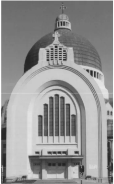
Among the nine churches built with concrete in Liège district [Gillard, 2010], Belgium, the Saint-Vincent Church (Fig. 14) is the oldest but also the first religious building designed by Robert Toussaint, then a young architect. It represents a very important witness, from historical perspective and technical points of view [Batir, 1936]. The construction of this church, completed in less than twenty months (Fig. 15), is
actually involved into the evolution and the urban planning extension of the city of Liège and the Universal Exhibition in Liège in 1905 [Gillard, 2011]. Erected near Mativa Bridge, designed by Hennebique [Batir, 1936], it was completed just before the celebration of the centenary of the Belgian independence.
Figure 14. Global view of Saint-Vincent church (May
2010)
Figure 15. Saint-Vincent Church before copper roofing placement (1930) [16]
Moreover, new material has been used in several parts of the edifice, mainly in the walls: Pauchot reinforced artificial stone [Gillard, 2011]. This material is named after the company that took in charge the structural work of the church. The family company of Pauchot brothers, originally based in Paris since 1919, was also active in Belgium (Brussels). It however ceased operations in early 1930, due to the economic crisis. There are currently very few traces of his accomplishments.
Massive church plan, of neo byzantine style, is centered on an oriented north-south axis, parallel to the Ourthe river, which borders the edifice (Fig. 16). Its length, reaching 57 m, is hardly larger than its width, 49 m, respectively.
Figure 16. Scheme and plan of Saint-Vincent Church [Technique des travaux, 1934]
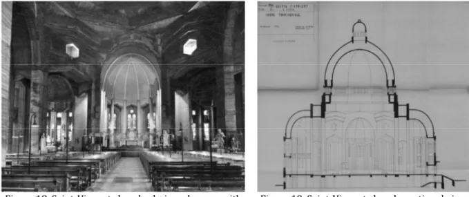
Figure 17. Parvis and bell tower in front of the Saint-Vincent Church A large dome (15m high - 22.40m diameter – 50.50m top) covers the building. It is protected with copper (now oxidized) as the peripheral semi-domes [Cornet, 1967]. The main entrance is south oriented. It is underlined by an arch and preceded by a parvis (Fig. 17). It provides access to the nave. The nave, covered by a half-cylinder and topped with a steeple, extends the central rotunda, in the form of irregular octagon
(Fig. 18); it is surrounded by a walkway, which separates itself the three main apses and four secondary apses (Fig. 16).
Figure 18. Saint-Vincent church, choir and apses, with part of rotunda (from www.kikirpa.be)
Figure 19. Saint-Vincent church: sectional view at the apses level with double concrete deck
(Dec. 10th, 1953).
There is a gallery which runs almost the entire church (along the facades). The slope of the land allows space under the choir, giving direct access to the basement.
Finally, the architect has ensured that the whole church is accessible: a stairway serving the building's basement to above the nave and a staircase used to reach the outer gallery, located under the central dome; there is a ramp, along the central interior dome which ends with a spiral staircase leading to the lantern on the top of the church (Fig. 23).
Archives shows that concrete was directly cast on the site and that traditional wooden plank sheeting (Figs 20 and 21) were used for casting; the absence of spacers resulted, in some cases, the positioning of the frame very close to the surface (Fig. 23).
Figure 20. Formworks and building of choir and apse (Jan. 15th, 1930) [Cornet, 1967]
Figure 21. Formworks and scaffolding for dome building (Nov. 7th, 1929) [Cornet, 1967] The main nave of Saint-Vincent church offers a double concrete structure, in the form of a frame (Fig. 22).
Figure 22. Saint-Vincent church: sectional view of the nave reinforced concrete frame and the structure [Technique des travaux, 1934].
The central dome, such as the half-domes and the roof covering the nave, are actually made of double bottom (Fig. 22). Reinforced concrete shells are connected with reinforced concrete beams like frames: it looks like a steel frame structure (Fig. 23). The roofs are made of a reinforced concrete shell with a thickness of 70 mm. The load of central domes is supported by eight hollow pillars, which delimitate the rotunda (Fig. 22). The inner vault of the nave is based on eight secondary pillars, while the outer one rests on pillars inserted in the facade. Loads are then transferred through beam-pillar systems.
Figure 23. Reinforced concrete frame structures (between dome shells)
Under the ground floor, a grid of beams transmits all loads to the pillars, resting on Franqui type piles (Fig. 24). About 230 piles were driven under the church, at a depth ranging between 10 and 12 m: the church is indeed above a backfilled ancient river deviation.
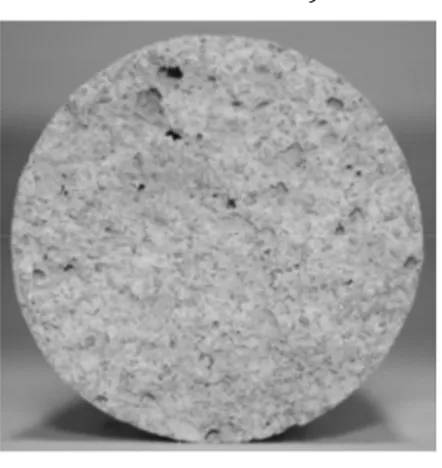
In general, the walls are made of a double structure. Samples taken through the wall at the ground level indicated the following composition (from inside to outside):
• a wall (apparently made of blocks) of concrete, 11 cm thick (Fig. 24); • a vacuum of 13.5 cm thick;
• Pauchot reinforced artificial stone, about 16 cm thick (Figs 25 and 26).
Figure 24. Sample of concrete (internal wall, Saint-Vincent church)
Figure 25. Internal face of Pauchot reinforced artificial stone sample from Fig. 24 (Saint-Vincent
church)
Figure 26. Sample of Pauchot reinforced artificial stone (external wall, Saint-Vincent
church)
Other samples showed different compositions, perhaps due to a too rapid execution of the work. Pauchot artificial stone, reinforced with wire mesh placed at 45°, is supposed to imitate the stone from France. False joints have also been painted on the facades.
Pauchot artificial stone material has been used for the outside part of the church walls; it may be considered as fulfilling material which is not submitted to external loading except dead weight.
Mechanical and physical performances (Table 3) have been evaluated on the base of cores from different locations around the church.
Table 3: Physical and mechanical properties of Pauchot reinforced artificial stone Sample Compressive strength [N/mm²] Tensile strength [N/mm²] Water absorption [% in mass] Specific mass [kg/m³] 1 18.1 1.48 10.86 1875 2 20.9 1.58 10.55 1887 3 19.7 0.78 10.69 2012 4 - 1.42 10.48 1941
Compressive strength is characteristic of a good quality mortar or a basic concrete. Tensile strength is maximum 0.8 times compressive strength; water absorption is quite high.
Capillary absorption tests have been performed in order to analyse water ingress and capacity of the mortar to resist to fluid penetration. The capillary suction test is described by Belgian standard NBN B 14-201: the water level above the bottom surface of concrete specimen is 5 ± 1 mm and the mass variation is measured after 5, 15, 30 and 45 minutes as well as after 2, 6 and 24 hours, respectively [Courard and Degeimbre, 2003]. Mass is measured on samples wiped off with a damp tissue.
The absorption coefficient, S, calculated according to NBN B 15-250, is given in Table 4: Table 4: Capillary absorption coefficients
Sample 1 2 3 4
S [kg/mm²/h1/2] 3,06. 10-6 3,06. 10-6 5,88. 10-6 2,45. 10-6
S [kg/m²/h1/2] 3,06 3,06 5,88 2,45
For repair mortars, the standard EN 1504-3 fixed at 0.5 kg / m² / h1/2 the upper limit for the absorption
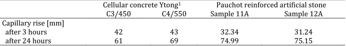
coefficient; the values given by the Pauchot reinforced artificial stone are much higher. They are related to the porosity of the material (see test water absorption in Table 1), which is itself linked to the low density samples. The Pauchot reinforced artificial stone is closer to a cellular concrete, as shown in Table 3, with regard to the values of capillary rise (Table 5).
Table 5: Capillary rise coefficients for cellular concrete and Pauchot reinforced artificial stone Cellular concrete Ytong1 Pauchot reinforced artificial stone
C3/450 C4/550 Sample 11A Sample 12A Capillary rise [mm]
after 3 hours 42 43 32.34 31.24
after 24 hours 61 69 74.99 75.15
Chloride content was measured twice for each of the three samples. The values, expressed as mass percentage of chloride ions, relative to the mass of cement, are shown in Table 6.
Table 6: Determination of chloride content
Sample 4H Sample 10 Sample 5
1 2 1 2 1 2
Chloride content [%] 0.031 0.033 0.038 0.031 0.029 0.031 According to EN 206-1, the maximum chloride accepted for concrete containing steel reinforcement or embedded metal varies between 0.20 and 0.40%. The values presented in Table 6 are far from the
1
Capillary rises into Ytong cellular concrete blocks measured according to standard NBN 538
threshold and can already rule out the possibility of corrosion due to attack by chlorides, for the samples considered
Carbonation depth was measured by using phenolphtalein indicator: some samples are completely carbonated (110mm) while others are only partially carbonated. It means that the material, which has been cast on site, was probably variable into its composition as well as its working procedure.
These considerations are confirmed by microscopical investigations.
Large air bubbles and voids are observed on thin slices samples (Fig. 27). Limestone sand seems have been used and CaCO3 crystals are numerous (Fig. 29): this is probably due to high lime content for
preparing mortar. Cement is however largely present in some samples, attesting the use of this hydraulic binder. The structure is lumpy. The grains of carbonates can be detached from the cement paste. Lime can be carbonated. There is no cohesion in cement paste and the interface between the grains of limestone is often broken (Fig. 28).
Figure 27. Optical microscope on Pauchot artificial stone
Figure 28. Cementitous matrix from Pauchot artificial stone (view ESEM)
Figure 29. Calcite crystals from Pauchot artificial stone (view ESEM)
The chemical and physical tests (Table 1) and microscopical observations (Figs 27 to 29) carried out on samples of Pauchot reinforced artificial stone revealed a heterogeneous material composition, more similar to a mortar or light concrete than a conventional reinforced concrete. It is porous and offers a compressive strength ranging from 11.1 to 20.9 MPa. The chemical analysis revealed a very low chloride concentration, eliminating the risk of corrosion attack of chlorides for these samples and favoring the hypothesis of corrosion by carbonation (the more likely that porosity of the artificial Pauchot stone is important and the urban environment in which the church is polluted).
500 µm
500 µm
The proper planning of investigations before carrying out repair works is important if optimum use is to be made of the test data. Engineers require guidance on both the techniques available for the condition assessment of structures and the methods for data interpretation. Two major stages are usually recommended for such an operation: the first stage is based on a rapid-scan visual assessment, often including limited sampling in areas obviously damaged, from which areas can be selected for more detailed investigations. The second stage contains a detailed diagnostic survey that relies on destructive and non destructive testing techniques [Cornet, 1967].
Non destructive techniques are more and more utilized not only for the evaluation of the concrete strength but also for the detection of cracks and delaminations.
In general, the concrete material may offer three types of damage: cracks, spalling or disintegration [Czarnecki, 2003].
Cracking mainly originates from structural problems as restrained deformations (with variations in
temperature and humidity), deformation of the support, unbalanced loading or horizontal stresses in alternating directions [20, 21]. The drying shrinkage or alkali-aggregate reaction may also lead to cracks but, in either case, cracks open moderate and are organized in a network (referred to as crazing).
Spalling means the debonding of pieces of concrete from their support. The dissociation follows tensile
stresses into concrete, often caused by corrosion of steel reinforcement. The problem may be further amplified by an action of frost on an area saturated with water.
Corrosion of steel can be due to an attack by chlorides (from de-icing salts or accelerators) or the
carbonation of concrete surrounding the reinforcement [Courard, 2009]. Too low cover of reinforcement promotes the corrosion reaction [Courard and Garbacz, 2010]. Finally, the disintegration of the concrete may also result from an attack by bacteria or acid products.
In Saint-Vincent church, a visual inspection was performed in order to identify damages and pathologies according to recommendations of Duvivier and Montfort [Duvivier and Montfort, 2008].
The main structural damages that have been reported are [Gillard et al., 2010]:
• cracks without specific direction, in front of the monument (Fig. 30),
• oblique cracks on the beams between the pillars of the rotunda or the pillars of the apses or
• vertical cracks on some of the pillars of apses (Fig. 31).
Figure 30. Crack in the central part of the beam above the by lighting the gallery (East front,
Saint-Vincent Church)
Figure 31. Vertical crack in a pillar (South West apse, Saint-Vincent Church)
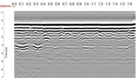
These last one may be related to the presence (confirmed by radar) of metal pipes discharging rainwater from the central dome; the origin of other vertical cracks however could not be yet identified on the basis of available information. In all cases, the installation of plaster witnesses would confirm a potential movement of the cracks. It will be followed, if necessary, by the installation of sensors, recording the movement of the lips of the cracks, providing the evolution of this movement over time.
Figure 32. Saint-Vincent Church : radar signal obtained from pillar between West and South-West apses.
The position of the vertical cracks visible on the front of the pillars coincides with the top half of hyperbole identified by the radar (Fig. 32). This would support the hypothesis attributing the presence of cracks to a deformation of the pipes, caused by freezing or by an insufficient flow diameter.
It may be noted that, in addition to the bombings of World War II, the Saint-Vincent Church suffered the earthquake of 1983. Later also held the derivation of a nearby stream, to the Ourthe river. After this diversion, settlements appeared in the gardens of houses adjacent to the church and it is not unlikely that the ground under the church has also borne the brunt of this change in water courses.
These three events have possibly exacerbated the movement of the structure.
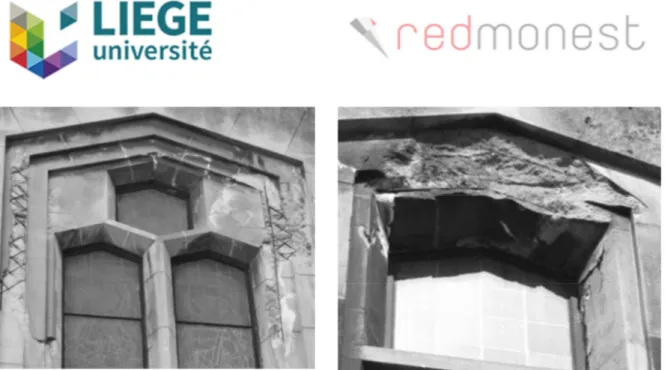
In addition, spalling was found as a main degradation all along the facade of the church (Figure 23), particularly around bays (Fig. 34). At this level, the cover of steel reinforcement is sometimes very thin (Figs 35 and 36). Other traces of spalling were visible in the stairwell and under the central dome (Fig. 23). Between the arches spanning the nave and the lantern, corroded steel bars are also flushing with concrete skin.
Figure 33. Spallings around the North West bay of the choir, Saint-Vincent Church
Figure 34. Spallings around a North bay, Saint-Vincent Church
Figure 35. Spallings under window sill, Saint-Vincent Church
Figure 36. Typical spalling inside Pauchot reinforced artificial stone, North West apse, Saint-Vincent Church
Finally, inside the church, along the gallery, traces of moisture have been noticed, at floor and ceiling levels. In some places, stains of rusty dirty walls or pillars.
7.
Saint-Vincent church global situation
The following conclusions may be reached from the present investigations concerning the behaviour of the Saint-Vincent Church:
• the degradations observed in Saint-Vincent Church are numerous but do not seem to jeopardize the safety of the faithful people;
• Pauchot reinforced artificial stone has been largely used as filling material for walls. Physico-chemical analysis shows a great variability and quite high porosity, which can be a source of degradations;
• main degradations are coming from concrete spallings, mainly due to carbonation effect and an insufficient recovery of steel reinforcement;
• structural defects are visible, mainly in the form of cracks and probably due to differential movements of parts of the structures. These differential displacements may be due to soil settlements or thermal gradients;
• particular attention should be paid to the presence of water and humidity, as a source of discomfort, but also damage by corrosion.
The situation of Saint-Vincent Church illustrates the problem that appears in several concrete religious monuments, yet often overlooked. In the district of Liège, an inventory, followed by a visual inspection, was performed. Much work remains to be done in that direction and within a relatively short time so that the management of these architectural witnesses remains possible.
8.
Hydrophobic treatment of concrete
As concrete is a porous material, it is essential to protect it against water penetration: hydrophobic treatments can provide a significant protection system. The EN 1504-2 standard defines hydrophobic impregnation as a concrete treatment for producing a water repellent surface. The inner surface of the pores is coated but the pores are not filled. No film forms on the concrete surface and appearance of the latter is slightly affected or unchanged (Fig. 37). The hydrophobic treatment will reduce the absorption of water, improve chemical resistance, reducing alkali-aggregate reaction and, if applicable, reducing chloride ion penetration.
Figure 37. Hydrophobic treatment principle. Figure 38. Interaction between water and a hydrophylic (top) or hydrophobic (bottom)
concrete surface.
The major objective of a hydrophobic treatment is to increase the contact angle of water (Fig. 38) and reducing surface free energy of concrete or mortar [Courard, 1999]. According to the equation of Young-Dupre (eq. 1),
(γSV - γSL) / γLV = cos θ (equation 1)
where γSL, γLV and γSV are the solid-liquid interfacial free energy and the surface free energy of liquid and
solid into contact with liquid vapour, respectively, and θ the contact angle (Fig. 4): if θ is increasing, it means that cos θ is decreasing. As γL is constant, it means also that γS is decreasing.
With increasing contact angle, less wetting of the surface will occur. Moreover, it will not penetrate the pore system of concrete if the surface of the pore has been treated: absorption forces become repulsion forces and water is “expulsed” from the surface [Courard et al., 2011].
Some products induce hydrophobic film formation that badly resists in alkaline media (even if alkalinity was necessary for the initial reaction). But the most common products belong to the silane family. Various kinds of silanes result depending on the different alkoxy or alkyl groups linked to the silicon atom. These products do not act all in the same manner (Fig. 39): in general, the larger the molecule of the alkyl group,
the better the water repellency of the silane. The silane molecules are very small (10 to 15 Angstroms) and can penetrate even a very few porous concrete. Penetrations of more than 5 mm in concrete [De Vries et al., 1998] are observed.
Figure 39. Influence alkyl group type on the hydrophobic efficiency of a silane [Courard et al., 2003]. Some silanes with alkoxy groups may polymerize if, during the application, they come into contact with water [Courard et al., 2003]. The water repellency of concrete treated with silanes has been found to be still effective after 35 months exposure to outdoor climate: these products have durable effect on water absorption [De Vries et al., 1998].
A second group of this family is constituted by oligosiloxanes. Siloxanes react with the silica contained in the concrete to form a hydrophobic layer. Siloxane molecules are oligomers and therefore larger than the silane molecules (25 to 75 Angstroms). These products cannot penetrate as deeply into the surface and may not be appropriate for the protection of dense concretes.
In this research project, existing products – mainly based on silanes and siloxanes were subjected to different ageing processes including UV radiation, moistening cycles, thermal shocks, freeze-thaw cycles and carbonation and efficiency has been evaluated on the base of contact angle, capillarity absorption, vapour and chloride permeability.
9.
Experimental program
The concrete formulation was prepared following standard NBN EN 1766 using CEM I 52.5 and W/C ratio of 0.7. The design of low quality concrete was intended in order to simulate old concrete coming from cultural heritage. Six batches were prepared with the same mix; each one produced five slabs (40x40x8 cm). Each slab was cut into four samples of 20x20x8 cm; 8 cm cylindrical samples were cored into slabs for permeability, capillary absorption and chloride ion diffusion tests. All samples were stored for 28 days in a humid chamber (90% RH); and then they were placed in a chamber at 23°C and 60% relative humidity for drying before applying the hydrophobic treatments. Four samples at least are prepared for each combination of test and products.
As the study focuses on the durability of hydrophobic treatments on existing concrete structures, only superficial water-repellents treatments were tested. The products selected correspond to those in used in North Western Europe climate conditions. Duplicate sets of samples were treated with either of two products: the first, a water-based water repellent commercial product. The data sheet defines it as an alkyl alkoxy silane product, henceforth referred to as “water based”. The second product was a hydrophobic siloxane mix in an alcoholic solvent, henceforth referred to as “solvent based”. The hydrophobic treatments were brushed on to the surface of the samples, following the recommendations of the manufacturer. The studied face is the smooth “mold face”. This side is intended to represent the external wall of a building.
Permeability to water vapour
The water-vapour transmission rate was evaluated according to the dish method for free films, following to the ISO 7783. This test uses a difference in relative humidity between the two faces of a sample. The water-vapor permeability rate is determined as a function of the amount of water vapor which passes through the specimen. For this test, cylindrical samples of 8 cm diameter and 3 cm thickness were prepared. The lateral faces were waterproofed with epoxy resin. The sample is set on a glass cup and the edges are sealed with wax in order to reduce moisture transfer to only one direction. A saturated solution of potassium nitrate KNO3 guarantees a relative humidity of 93.2% in the cup. The device is placed in a conditioning chamber where the relative humidity is 60% at 20°C. The thickness of the equivalent air layer is evaluated. The standard proposes also a classification of samples in three classes by water-vapor transmission (Table 7).
Table 7: Classification by water-vapor transmission equivalent layer
Class Sd (meters)
High (I) <0,14
Medium (II) 0,14 to 1,4
Low (III) > 1,4
Liquid water permeability (capillary absorption)
The measurement of the liquid water transmission coefficient w was carried out following standard EN 1062-3. Cylindrical samples with 8 cm diameter and different of heights were prepared. Only one face is treated with water-repellent, the others are waterproofed with epoxy resin. The treated face is immersed in 5 mm water and the sample is weighed after 1h, 2h, 3h, 6h and 24h. The coefficient of water-liquid permeability w is calculated from the slope of the linear part of the curve (Table 8).
Table 8: Classification by liquid water permeability
Class Liquid water permeability w (kg/m2h0,5)
High (I) > 0,5
Medium (II) 0,1 to 0,5
Low (III) <0,1
Chloride ions permeability
An accelerated chloride permeability test was performed. This test followed standard ASTM C 1202-97 [24]. The test principle is to apply a 60V current passing through the sample. The sample is in contact with both cells through the railings. One cell contains a 0.3 M NaOH solution and the second a 3% w/v NaCl solution. The positive terminal of the generator is connected to the NaOH reservoir and the negative terminal on the NaCl one (Fig.40). The test consists in measuring the intensity of the current generated by a constant voltage of 60V maintained for 6h. The current induces the Cl- in the sample to move towards
the positive terminal; the more chloride ions pass through the sample and the higher the current. The amperage is measured every 30 minutes for 6 hours. Core samples of 8cm diameter and 5cm thick were used. The lateral faces of the samples were covered with epoxy resin. Before testing, the samples were immersed for one week in a solution of NaOH for saturation
Figure 40. Diagram of the electrical assembly for chloride ion permeability.
Following ASTM C 1202-97 recommendations, the electric charge passing through the sample can be determined as follows:
900 ⋯
Where is the amperage after i minutes. This equation is valid for sample with a section of 95 mm. A correction is needed:
∗ 3.158
3.75
∗ is the electric charge passing through a sample of 50mm (3,158 in) of diameter. The standard proposes
a classification of samples according to their chloride ions penetrability (Table 9). Table 9: Chloride ion penetrability based on charge passed (ASTM 1202-97)
Charge Passed (Coulombs) Chloride Ions Penetrability
> 4000 High (I)
2000-4000 Moderate (II)
1000-2000 Low (III)
100-1000 Very Low (IV)
<100 Negligible (V)
Contact angle measurement
A water drop is placed with a computer-assisted syringe on to the sample surface. The contact angle between the hydrophobic surface and the droplet of water (Fig.4) is measured by a CDD camera linked to the computer.
Accelerated ageing
UV light exposition
To simulate the deterioration process caused by sunlight, the samples were placed in a chamber to expose the treated face with UV-A lamps. The lamps are electrically equivalent to an ordinary 40-watt fluorescent lamp. It provides a simulation of sunlight in the critical short wavelength region from 365 nm down to the solar cut off of 295 nm. Its peak emission is at 340 nm. This device provides cycles of 4 hours of UV exposition followed by 4h of condensation, for a total duration of 700 hours.
Freeze/thaw cycle
The samples were exposed to 20 freeze/thaw cycles. For each cycle, the samples were immersed for two hours in salted water at -15°C then immersed in water at ambient temperature for two hours. Just one surface is exposed, while the others are sealed with epoxy resin.
Thermal shocks
Each sample was exposed to infrared lamps (245V, 250W) and a water-jet in a storm simulation tank; the face of samples offer slight inclination of about 3º (relative to the horizontal) to allow water to flow quickly. The surface temperature can reach up to 60°C. For each cycle, the samples are exposed to infrared lamps for 5h 45min and then sprayed with water at 12°C for 15 minutes. The samples are exposed to 20 freeze/thaw cycles followed by 10 thermal shocks cycles. Tests were performed on the same samples that underwent freeze/thaw cycles
RH cycling
For this test, the six faces of the 20x20x8 cm samples were treated with one or the other hydrophobic agents and four samples for each agent were tested. The test consists in exposing the samples to four cycles of different relative humidity: each cycle lasts for two weeks: the samples are first stored in an atmosphere of 90% RH (for 1 week) and then 50% RH (for 1 week).
Carbonation
The resistance to the carbonation process induced by the applied hydrophobic agent was also assessed. The samples are exposed to carbonation for one month. The conditioning chamber contains a gaseous mix with a CO2 concentration of 50% (v/v) and a 60% RH. The space in the chamber is limited, and small
samples (20cmx8cmx8xcm) were used. The hydrophobic agent was applied on the six faces.
The wettability of a surface is directly related to the value of the contact angle between the water droplet and the solid. The contact angle evolution after ageing is given in Figure 41. The contact angle for untreated concrete is below 50°. We note that, before ageing, both products meet already requirements, especially siloxane treated, which leads to high hydrophobic behaviour (145°). The obtained data show that even after subjected to artificial ageing, the products keep their hydrophobic performance. Nevertheless, in two cases, the products lose their performance reaching angles below 90°: the water based product with UV light exposure and the solvent based with the thermal shocks cycles. The UV light exposition destroys a part the Si-O-Si bonds between the hydrophobic molecules and the substrate, inducing a decrease of the hydrophobic behaviour of the surface. Repeating thermal shocks may cause irreversible structural modifications of the polymer and induce a partial depolymerisation. Moreover, the sudden drop in temperature damaged the quality of the hydrophobic treatment due to differences between the thermal expansion coefficients (concrete/coating). Considering the contact angle standard, the effectiveness of the solvent based product treatment is better than the water based product.
The efficiency of hydrophobic treatment on water absorption reduction is evident (Fig. 42). The value decreases from 0.112 kg/m2h0,5 for untreated samples to 0.0405 kg/m2h0,5 for solvent based product
treated and to 0.0058 kg/m2h0,5 for water based product treated sample. The water based product seems
to be more effective as the w coefficient has a ten-fold decrease compared to sample treated with solvent based product thus significantly reducing water penetration. Most ageing processes slightly degrade the effectiveness of water-repellent with regard to water permeability, but without compromising their performance. In fact, for every ageing process except thermal shocks, the sample remains in the low permeability class (<0.1 kg/m2h0,5).
Figure 41. Water contact angles (°) after ageing.
For the water based product, the coefficient of water-liquid permeability stays at a low value (0.05 kg/m2h0,5) for each ageing process except for thermal shocks. After this ageing, the surface of the water
based product treated sample was badly degraded which explains the high coefficient measured after this ageing. On the other hand, the solvent based product treatment offers a good resistance to ageing exposure and stays in the low class permeability. The UV light ageing process is less critical for water absorption performance than for contact angle standard because the Si-O bonds remain intact in the deep on the concrete. The carbonation process tends to reduce the concrete porosity but also the alkalinity that negatively impacts hydrophobic treatments stability.
Figure 42. Coefficient of water-liquid permeability w after ageing (kg/m2h0,5).
The resistance to chloride ion penetration was performed before after UV light ageing (Fig.43). Before ageing, both untreated and treated samples present moderate chloride ions permeability (II). The values are between 2900 C and 3900 C. After UV lights ageing, the chloride penetration resistance is critically diminished by almost twice as much for both water-repellents. For the solvent based product, the corrected charge increases from 2914 C to 4910 C, and for the water based product from 3446 C to 6007 C. The treated concretes fall then into another classification group (I) and present a high level of chloride ion penetrability. The solvent based product is more efficient against chlorides penetration than water based product before ageing and after UV treatment. As already mentioned, the UV light partially destroys
untreated
water based product solvent based product
untreated
water based product solvent based product
the Si-O coating/substrate bonds, decreasing the resistance to water-permeability and facilitating the NaOH solution penetration.
Figure 43. Chloride ion penetration before and after UVA exposure (corrected electrical charge Q (Cb)). As usually requested, the use of hydrophobic agents doesn’t significantly modify the water-vapour permeability of concrete. The results show that the concrete has an intrinsic low permeability to vapour (Fig. 44). Before ageing, the use of the both hydrophobic agents slightly decreases the water-vapour permeability (Sd = 3 m for untreated, 3.6 m for water based product and 4.3 m for solvent based product treated, respectively). This significance may be due to g high silane and siloxane molecular weight (siloxane is bigger than silane) and can reduce the superficial porosity of concrete. After each ageing, the values are close and remain in class III. The differences can be explained by a sampling effect because the intrinsic parameters may have little influence on the results (aggregate placement, variation in porosity, etc.).
Figure 44. Water-vapour permeability after ageing (equivalent layer Sd (m)).
Consequently, in order to reduce the natural deterioration of concrete used in cultural heritage buildings, the durability of two water-repellent agents was assessed after various artificial ageing exposures. Five ageing processes were applied on concrete samples treated with the water-repellents and the changes of the measured properties assessed.
Thermal shocks and UV-A exposure are the most critical ageing process: UV light may break the Si-O-Si bonds of solvent based product molecules at the surface of the concrete; however, molecules that penetrated into it may remain intact. The thermal shocks cause irreversible structural modifications and damage bonds by differential thermal dilatation coefficient.
untreated
water based product solvent based product
untreated
water based product solvent based product
The hydrophobic treatments tested showed a very low influence on the water-vapour permeability. Such treatments do not prevent the transfer of moisture in and out of the concrete. Regarding the water-liquid permeability and the contact angle, as expected, the products offer a very good behavior and improve the permeability class. In most case, they resist very well to ageing processes and don’t lose effectiveness. The solvent based product tested is more effective than the water based product. It offers better intrinsic properties and proved more durable during laboratory ageing. Moreover, only the solvent based product remains stable and neutral from visual color evaluation after undergoing different ageing procedures. The nature of the solvent can be an explication. The solvent based product uses an alcohol solvent which is more effective than the aqueous solvent, but is more problematic for ecological considerations.
The application of either a solvent- or water-based hydrophobic treatment has an important influence in reducing concrete deterioration and can be a solution for the preservation of cultural heritage that uses this material. It reduces water penetration into concrete and remains effective even after weathering. However, the combination of several ageing factors may affect its durability. This can be remediated by periodical reapplication of these treatments thus avoiding their loss of performance over time
10.
Evaluation of material efficiency
The objective of this study is to determine if hydrophobic treatments also have an influence on the propagation of the carbonation front into the concrete. Capillary absorption tests, permeability to water-vapor and oxygen, FTIR, DSC and porosity were carried out on concrete samples. Six products with different concentrations, solvent and molecules were tested (Table 10).
Table 10: Hydrophobic products characteristics
Molecule Solvent Active product
concentration (%) Density (g/cm3)
Silane Water 20 1.01
Siloxane White spirit 7.5 0.83
Silane/siloxane Water 8 1.10
Silane - 99 0.90
Silane cream 80 0.90
Silane water 40 0.95
The concrete was designed on the base of CEM I 52.5, Rhine sand (0-4mm) and Moselle gravels (4-8mm). Specimens were cured for 28 days at 95%RH and 20°C. They are stored afterwards at 60% RH and 21°C. The hydrophobic products are applied according the prescriptions of the producer.
Carbonation acceleration test is performed in specific incubator with 3% CO2 concentration and 60%
relative humidity. Beam of 40cmx10cmx10cm are exposed carbonation incubator; every 2 weeks, a slice of 1cm thick is sawed and carbonation depth is measured.
Figure 45. Evolution of the capillary absorption without and after treatment.
Effect of silane on capillary succion is more visible on more porous concrete (Fig. 45). Concentration doesn’t appear to be fundamental for concrete with high W/C ratio’s, which means classical concrete from cultural heritage.
Figure 46. Evolution of the carbonation depth as a function of time (W/C = 0.5)
Carbonation depth (Fig. 46) decreasses with silane concentration: the repulsive effect on water seems to be effective for reducing concrete carbonation process, which is fundamental for reducing steel corrosion
Figure 47. Evolution of the carbonation depth (mm) as a function of time (W/C = 0.7)
For high W/C (Fig. 47), carbonation speed is lightly higher when hydrophobic impregnation has been used and the speed of carbonation lightly increases when active product concentration increases.
Figure 48. Evolution of the carbonation depth (mm) as a function W/C ratio and hydrophobic product concentration (CEM I 52.5).
Comparing W/C ratios (Fig. 48), it is clear that, for low W/C, speed of carbonation is lower when concentration of hydrophobic product is high. For higher W/C (0.7), speed of carbonation is higher when concentration of hydrophobic product is high.
Figure 49. Visual observation of hydrophobic treatment penetration (mm) (CEM I 52.5).
Visual observation by means of drop of water on the slice of the specimen reveals that the depth of penetration increases when W/C increases: higher porosity induces deeper penetration. Moreover, depth of penetration increases when active product concentration increases.
Figure 50. FTIR on untreated concrete - FTIR on concrete with hydrophobic impregnation
A method based on infrared spectroscopy (FTIR) and, specifically, the detection of peaks [2800-3100cm-1]
corresponding to vibrations of (CH2-CH3) bonds has been developed (Fig. 50). The surface Sx under the
curve (Fig. 51) represents the level of saturation of the concrete at the corresponding depth (Sx = Ax/Asaturated).
Figure 51. FTIR on concrete with hydrophobic impregnation Ax : surface under the curve
Asaturated : surface under the curve for hydrophobic impregnation saturated concrete
Sx = Ax/Asaturated
This method has been used in order to calculate the depth of penetration of the hydrophobic treatment.
Figure 52. Evaluation of the depth of penetration by FTIR (W/C = 0.6)
Silane is more efficient in penetrating the concrete (W/C = 0.6) with regard to siloxane due to dimension of molecules. Higher concentration of active matter induces an increase of penetration as well as saturation level (Fig. 52). Generally, the percentage of saturation S (%) is decreasing with depth and is higher for higher concentration of hydrophobic product. Probably due to the higher length of molecular chain, depth is lower for siloxane.
Figure 53. Evaluation of the depth of penetration by FTIR (W/C = 0.7)
Moreover, penetration depth is higher for higher W/C (Fig. 53) which means that S is higher for higher W/C.
Capillary absorption coefficient is evaluated in accordance with EN 1062-3 (Coating materials and coating systems for exterior masonry and concrete. Determination of liquid water permeability).
Figure 54. Capillary absorption coefficient C (g/m2s1/2) vs W/C ratio and type of hydrophobic
treatment
It is shown (Fig. 54) that hydrophobic impregnation is more efficient with regard to capillary absorption when porosity increases and when hydrophobic product concentration increases.
Figure 55. (Cuntreated/Ctreated) vs W/C ratio and type of hydrophobic treatment
The efficiency of the hydrophobic treatment is presented by means of the coefficient Cuntreated/Ctreated and shows that hydrophobic impregnation more efficient for higher W/C.
Figure 57. Figure B: Mercury Intrusion Porosimetry carbonation after 45 days - W/C=0.6 – CEM I 52.5 For concrete with W/C equal to 0.5 (Fig. 56) and 0.6 (Fig. 57), carbonation induces a decreasing porosity [50-100nm].
Figure 58. Mercury Intrusion Porosimetry carbonation after 45 days - W/C=0.7 – CEM I 52.5 Carbonation seems to have a limited effect on pore volume (Fig. 58) on concrete with W/C = 0.7, even it increases Medium Diameter of pore. Carbonation increases also pores greater than 100nm (increasing permeability).
Figure 59. Drying speed (g/m²h) vs W/C ratio and concentration of hydrophobic product
Capacity of drying is evaluated in accordance with EN 13579 (Products and systems for the protection and repair of concrete structures. Test methods. Drying test for hydrophobic impregnation). The speed of drying of the concrete is increasing with W/C (Fig. 59). For low W/C, the speed of drying of the concrete is decreasing with hydrophobic treatment.
Table 11: Drying speed (DRC is corresponding to the drying speed ratio between the treated and the untreated sample)
DRC (%) W/C 0.5 0.6 0.7
Silane 40% 55.98 72.71 102.84
Silane 80% 52.43 76.36 98.30
Finally (Fig. 60), there is no main difference vs molecule or concentration (Table 11). However, the higher W/C, the higher drying speed.
Figure 60. Drying speed (DRC in %) vs W/C ratio and type of hydrophobic product
The results showed that the application of a water-repellent delays the propagation of the carbonation front. The most efficient products were the silanes which presented a higher penetration depth. Concrete compactness and porosity played also an important role in silane penetration depth. The main conclusions are:
• Hydrophobic impregnation impact on carbonation = f(W/C)
o Decreasing carbonation for low W/C o Increasing carbonation for higher porosity
• Hydrophobic impregnation penetration depth is largely higher for high W/C
• Decrease of drying speed for low W/C
• Speed of carbonation ↓ when hydrophobic impregnation concentration increases
• Speed of carbonation ↓ when hydrophobic impregnation penetration depth increase
• Hydrophobic impregnation penetration depth and concentration have an influence on drying speed
11.
Concrete cultural heritage inventory
Cultural heritage in Belgium is managed by regions. For Wallonia, IPW (Walloon Heritage Institute) is responsible for the inventory. In 2015, 4021 buildings are inventoried, within 3 mains types of classification:
• Listed in the inventory,
• Classified buildings,
• Exceptional heritage of Wallonia.
Since 2015, there is an access to IPIC inventory through informatics files on www.ipic.be. These files have been checked in order to point out the cultural heritage in which concrete is main material used (Fig. 61).
Figure 61. File identification for cultural heritage buildings
A list has been established after reading each file and a classification has been proposed in accordance with LRMH for the description of the building (Fig. 62):
• Environment: industrial, city, rural, …
• Category: school, religious, military, civil, …
• Architect
• Date of erection
• Classification mode
Figure 62. File for listing concrete cultural heritage in Wallonia The localization of the inventory and the classification is given in Table 12 and Fig. 63. Table 12: Classification of concrete cultural heritage vs province
Province In the inventory Classified building Exceptional heritage in Wallonia Brabant Wallon 444 4 1 Hainaut 83 3 0 Liège 180 10 3 Luxembourg 43 0 0 Namur 51 4 0 TOTAL 401 21 4
Figure 63. Localization of concrete cultural heritage in Wallonia On the base of the analysis, it is observed that the concrete cultural heritage represents:
• 10% of the inventory,
• 3,2% of classified buildings,
• 2,1% of the exceptional heritage
It is distributed in different applications but agriculture, infrastructures and religious buildings seem to be the most represented (Fig. 64).
The first conclusions let us to conclude that, on the 401 monuments listed in the survey, most of them are coming from domestic and sacred architecture. The majority was built between 60’s and 80’s and the environment in which they are is mainly rural (71%). Most interesting is that 89% of them are still in service, which is a guarantee of minimum maintenance, even if not always suitable. Only a small representation of concrete heritage is present in the list of protected monuments (<5%).

![Figure 22. Saint-Vincent church: sectional view of the nave reinforced concrete frame and the structure [Technique des travaux, 1934]](https://thumb-eu.123doks.com/thumbv2/123doknet/6644449.181498/14.892.239.649.182.423/figure-vincent-sectional-reinforced-concrete-structure-technique-travaux.webp)

![Figure 39. Influence alkyl group type on the hydrophobic efficiency of a silane [Courard et al., 2003]](https://thumb-eu.123doks.com/thumbv2/123doknet/6644449.181498/22.892.270.637.236.520/figure-influence-alkyl-group-hydrophobic-efficiency-silane-courard.webp)
