HAL Id: hal-02196898
https://hal-mines-albi.archives-ouvertes.fr/hal-02196898
Submitted on 5 Feb 2020
HAL is a multi-disciplinary open access
archive for the deposit and dissemination of
sci-entific research documents, whether they are
pub-lished or not. The documents may come from
teaching and research institutions in France or
abroad, or from public or private research centers.
L’archive ouverte pluridisciplinaire HAL, est
destinée au dépôt et à la diffusion de documents
scientifiques de niveau recherche, publiés ou non,
émanant des établissements d’enseignement et de
recherche français ou étrangers, des laboratoires
publics ou privés.
Modeling of IR lamps with coated reflector used in the
slurry powder impregnation process of composite tapes
Jennifer Mackie, Olivier de Almeida, Fabrice Schmidt, Karine Labastie
To cite this version:
Jennifer Mackie, Olivier de Almeida, Fabrice Schmidt, Karine Labastie. Modeling of IR lamps with
coated reflector used in the slurry powder impregnation process of composite tapes. ESAFORM 2019
- 22nd International ESAFORM Conference on Material Forming, May 2019, Vitoria-Gasteiz, Spain.
�10.1063/1.5112665�. �hal-02196898�
Modeling of IR Lamps with Coated Reflector Used in the
Slurry Powder Impregnation Process of Composite Tapes
Jennifer Mackie
1, 2, a), Olivier De Almeida
2, b), Fabrice Schmidt
2,c),
Karine Labastie
1, d)1IRT Saint Exupéry, 118 route de Narbonne – CS 44248, F – 31432 Toulouse Cedex 4, France
2ICA, Université de Toulouse, CNRS, IMT Mines Albi, UPS, INSA, ISAE-SUPAERO, Campus Jarlard, 81013 Albi CT Cedex 09, France
a)Corresponding author: jennifer.mackie@mines-albi.fr b)olivier.dealmeida@mines-albi.fr
c)fabrice.schmidt@mines-albi.fr d)karine.labastie@irt-saintexupery.com
Abstract. This study proposes a modelling strategy to simulate the heating stage during the production of thermoplastic
composite tapes. Impregnation using a slurry powder technique with carbon fibres and PEKK (PolyEther-Ketone-Ketone) requires a heating step, achieved with an infrared (IR) oven, to evaporate the water and melt the polymer powder. These phenomenon are highly temperature dependant justifying the need to characterise heat transfer within the infrared oven.
In the literature, most of the models refer to clear lamps with Lambertian emission. The case of tubular lamps with coating on the back-side (i.e. integrated reflectors) then needed to be investigated. The reflector greatly modifies the lamps spatial emission, so a single emissivity and temperature assumption is no longer sufficient. Here we propose an adaption of the radiosity method to predict spatial emission accounting for a ceramic coated reflector in terms of radiative exchange. Inverse analysis was used to characterise the emission of these lamps. An IR camera (FLIR SC325, [7.5-13] µm) was used to perform measurements on the back surface of a heated ABS (Acrylonitrile Butadiene Styrene) plate for which radiative as well as thermophysical properties are known form previous in-lab research works [1]. Temperature distribution results were transferred into the commercial software COMSOL Multiphysics® to estimate model parameters: filament temperature and an emissivity distribution function.
INTRODUCTION
In recent years there has been a growing interest for the use of composite materials in the aeronautical industry. Thermoplastic composites are of particular interest as they can be welded or reshaped and recycling is possible. Processes like automated tape laying use thermoplastic composite tape to create larger structure [2][3]. Different processes can be used to create these tapes such as fusion impregnation, fiber commingling, film stacking or powder impregnation [4]. In the case of wet powder impregnation (slurry powder) the wet impregnated tape undergoes a series of heating steps to evaporate the water [5] and melt the polymer powder [6]. These phenomenon are highly temperature dependent and to better understand the evolution of the product during these steps it is first necessary to understand the heating conditions applied.
In the slurry powder impregnation process under study, the thermoplastic tape is heated using radiative technology. An oven composed of multiple infrared halogen lamps, reflective panels, glass plates, cooling air injection and air extraction system is used. Here the lamps have an integrated reflector in the form of a fine coating on the underside of the glass tube contrary to clear lamps with Lambertian emission that are more commonly used [7],. This reflector modifies the spatial distribution of the lamps emission. Methods such as ray tracing [8] can be used to model this type
of emission but is highly time consuming, especially for a high number of emitters. This motivated the need to find a simpler model capable of predicting the lamps emission with reasonable computation time.
This study then proposes a modeling approach based on the radiosity method for the case of lamps with integrated reflector. The strategy used consisted in applying a weight factor to the emitted power around the circumference of the lamp so as to represent the spatial distribution of the emitted radiation. The values of the different weight factors were identified from the comparison of numerical data with experimental data recorded with a specific experimental set up by using an inverse analysis method.
First, the infrared lamps and experimental procedure are presented. Then, a focus on experimental results is carried out before developing on the numerical model and identification of the model parameters.
EXPERIMENTAL PROCEDURE
Infrared Lamps
‘Clear’ halogen infrared lamps are composed of a tungsten filament, a tubular quartz case and a small quantity of halogen gas. Because of the helical shape of the tungsten filament, the radiative emission of this type of lamp is Lambertian and mostly depends on filament temperature. This temperature in turn is determined by the supply voltage as the lamp is heated using Joule heating. In this study halogen IR lamps (Dr. Fischer-2000W, 400V) with an integrated reflector are studied (Fig. 1). The integrated reflector is a fine coating on the underside of the quartz tube. This coating effects the overall emission of the lamp by redirecting part of the filaments radiation towards the front and away from the back. As the filament temperature varies with supply voltage so does the spectral emission of the lamp. For nominal filament temperature the wavelength of maximal emission is λmax=1.2 µm with 95% of emission
in the range [0.6;6] µm. By determining the relationship between supply voltage and filament temperature the evolution of this range will also be determined.
(a) (b)
FIGURE 1,. (a) Infrared halogen lamp with integrated reflector,(b) schematization
Experimental setup
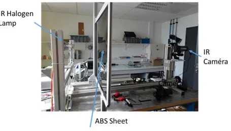
The experimental setup used to evaluate the infrared lamp’s filament temperature and spatial distribution function is presented in Fig. 2. The infrared heating was achieved by controlling the supply voltage U (V) applied to the tungsten filament. The lamp thus heated a flat panel on its front side, and the temperature on the back side of the sheet was measured using an IR camera (FLIR SC325, [7.5-13] µm). The lamp was directed with the ‘clear’ side facing upwards and the reflector facing downwards as can be seen in Fig. 1, and was positioned centrally to the panel.
FIGURE 2. Experimental set-up
Material
The material used in the experimental set up was a flat sheet of ABS (Acrylonitrile Butadiene Styrene), an amorphous thermoplastic polymer. The main thermal and optical properties of ABS can be found in Table 1. The panel used in this study was 680 x 670 x 1.5 mm.
TABLE 1, Thermal properties of ABS [9]
Properties ABS
Specific heat capacity Cp 1300 W.kg-1.K-1
Thermal conductivity k 0,19 W.m-1.K-1
Density ρ 1050 kg.m-3
Glass transition temperature 105°C Integrated emissivity ([0.95-20] µm) ε 0,94
EXPERIMENTAL RESULTS
The temperature field on the back face of the ABS sheet was measured for supply voltages ranging from 20% to 100% of nominal voltage (400V). For each experiment the sheet was heated until a temperature of 50°C was reached, the lamp was then turned off and the cooling of the plate was recorded. This temperature was chosen to assure the panel maintains a much lower temperature than the glass transition temperature of the material For certain measurements, the power of the lamp did not allow the ABS to reach the maximum temperature desired, in this case the lamp was shut off when the temperature variation was negligible however it is important to note that a steady state was not reached.
Figure 3 shows the temperature field on the back face of the ABS sheet in the last instants of heating. The point of maximum temperature is shifted vertically towards the top of the panel as an effect of the reflector. This point can be seen on the example given in Fig 3(a), it serves as the intersection point for perpendicular and parallel profiles that will be used for the optimization step. The evolution of the temperature of this point versus time can be observed Fig. 3(b).
(a) (b)
FIGURE 3, (a) Temperature field at heating time t=546 for U=160V. Profiles perpendicular and parallel to the lamp intersect at
the point of maximum temperature, (b) Temperature versus time for the point of maximum temperature.
NUMERICAL SIMULATION
Model
To model the Lambertian emission of a ‘clear’ lamp only the filament needs to be considered [10]. The spiraled filament is approximated by an equivalent cylinder, to which a temperature T (K) and integrated emissivity εf (T), is
applied in order to define the lamp’s radiosity J (W.m-2) according to Eq.1 where σ=5.670367e-8 W.m-2K-4 is the
Stephan-Boltzmann constant.
4
)
(
T
T
J
f
(1)For a lamp with a coated reflector, this model has to be extended. A model capable of taking into account spatial effects in the form of a distributive function on the filaments emissivity was thus proposed. As described with Eq. 2, the filament circumference was divided into n zones (6 zones in Fig. 4(b)), emissivity was weighted by a coefficient ki. The sum of these coefficients should be equal to the number of zones to conserve transmitted power by the filament
(Eq. 3).
)
(T
k
i f i
(2)
6
1
6
1
ik
i (3)Numerical simulation was carried out using commercial software COMSOL Multiphysics®. Boundary conditions were assumed only radiative and convective on the front and back faces of the sheet (Eq.4), thermal insulation was applied to the four edge faces.
)
(
)
(
)
(
k
T
h
T
T
T
4T
4n
air
air
(4)As a first approach, convection in this study was taken to be constant and equal to an average value h=4.5 W.m-2.K-1
calculated using the data from the cooling phase of the tests.
In this model 400 hexahedral elements were used to mesh the panel. The Biot number was estimated and was found to be inferior to 0.1, surface heat transfer is there for dominant over conduction within the material, simulations were carried out with only one mesh in the thickness of the ABS sheet to reduce computation time. Filament temperature is assumed constant and homogeneous during the simulation. The filament surface was meshed with 360 quadrilateral elements.
(a) (b)
FIGURE 4, (a) Simulation geometry, (b) Filament model
Optimization
Parameter optimization was carried out using the SNOPT solver [11] implemented in COMSOL Multiphysics®. The work presented in this section was carried out for a supply voltage U=160V with a Least-Squares objective function (Eq. 5). Initial and optimized values of the control variables can be found in Table 2. This optimization was carried out considering the coefficients ki positive and inferior or equal to unity, however the condition given by Eq.
3 was not implemented as a first approach.
2exp
)
(
min
T
T
num (5)TABLE 2, Optimized lamp parameters
Properties k1 k2 k3 k4 k5 k6 Tlampe (K)
Initial value 1/6 1/6 1/6 1/6 1/6 1/6 1900 Optimized value 0.63023 0.19598 0.10211 0 0 0.36477 1899.9
The surface temperature distribution at the end of heating time th is shown in Fig, 5 (a), the overall profile is very
similar to that of the experimental results. Figure 5 (b) shows a comparison between the experimental data and the simulated temperature for the perpendicular profile. The agreement is fair between the simulated profile and the experimental data with the exception of the maximal peak. The global error on the temperature taken over the whole face was found to be 2.8%.
The reflector redirects a percentage of the filament’s emission towards the front of the lamp but the coating is not opaque, as a result the remaining emission is transmitted through the back face of the lamp. The optimized values found in this study do not physically represent this situation as k4 and k5 are null. In the model this is compensated by
the remaining coefficients.
The lamp was turned by 90° so that the clear side was fully facing the ABS sheet. Using the optimized coefficients from Table 2, an error of 26.4% was found between experimental and numerical data. In further work optimization of the parameters will be carried out using Matlab®, data from multiple lamp positions will be used for the optimization and the constraint Eq. 3 will be implemented. This should allow to determine more physical coefficients representative of the overall emission of the lamp.
(a) (b)
FIGURE 5, (a) Optimized surface temperature on the back face of heated ABS sheet at th. (b) Comparison between experimental data and simulated heating with optimized parameters at th.
CONCLUSION AND PERSPECTIVES
This work proved promising for modelling infrared halogen lamps with an integrated reflector via an adapted radiosity method. A distributive function was proposed for modelling such a lamps emission and was found to give fair results for a given position. However, work still needs to be carried out taking into account the problem constraints in order to find values for the weighted coefficients that better represent the physical problem.
In this work an average convection coefficient was considered, further work should be carried out to better integrate convection into the problem.
Once the optimised distributive function is found, it will be integrated into a model of the IR oven and simulations will be carried out to compare experimental heating of an instrumented ABS sheet with the heating simulation.
ACKNOWLEDGMENTS
These results were obtained under the research project "METEOR" at the IRT Saint Exupéry in collaboration with the ICA. We thank the industrial and academic members of the IRT who supported this project through their contributions, both financial and in terms of specific knowledge: Industrial members: ARKEMA, SD TECH, CHOMARAT,AIRBUS, HEXCEL, HUTCHENSON, PORCHER. And Academic members: CNRT Materiaux
We also thank the Commissariat Général aux Investissements and the Agence Nationale de la Recherche for their financial support in the Programme d’Investissement d’Avenir (PIA).
REFERENCES
1. S.Andrieu, « Etude expérimentale et numérique du chauffage infrarouge de plaques thermoplastiques pour le thermoformage » Ph.D. thesis, ENMP, 2005
2. C. M. Stokes-Griffin and P. Compston, Compos. Part A Appl.Sci. Manuf., Vol 75, pp. 104-115 (2015)
3. V. Agarwal, S. I. Guçeri, R. L. McCullough and J. M. Schultz, J. Thermoplast. Comos. Mater., Vol 5, no 2, pp. 115-135 (1992)
4. S. R. Iyer and L. T. Drzal, Thermoplast. Comos. Mater., Vol 3, no 4, pp. 325-355 (1990) 5. K. Ramani and C. Hoyle, Mater. Manuf. Process, Vol 10, no 6, pp. 1169-1182 (1995) 6. K. Ramani and C. Hoyle, Mater. Manuf. Process, Vol 10, no 6, pp. 1183-1200 (1995) 7. M. Pettersson and S. Stenström, Int. J. Heat Mass Tranf., Vol 43, no 7, pp. 1209-1222 (2000)
8. B. Cosson, F. Schmidt, Y. Le Maoult and M. Bordival, Int. J. Mater. Form, Vol 4, no 1, pp. 1-10 (2011) 9. M. Dauphin, “Amélioration des simulations thermiques dans les systèmes d’éclairage automobile », Ph.D. thesis,
Université de Toulouse, 2014
10. S. Nakouzi, « Modélisation du procédé de cuisson de composites infusés par chauffe infrarouge », Université de Toulouse, 2012
11. P. E. Gill, W. Murray and M.A. Saunders, « User’s Guide for SNOPT Version 7: Software for Large Scale Nonlinear Programming” Stanford University,2007.