HAL Id: hal-02114092
https://hal.archives-ouvertes.fr/hal-02114092
Submitted on 16 Jul 2019
HAL is a multi-disciplinary open access
archive for the deposit and dissemination of
sci-entific research documents, whether they are
pub-lished or not. The documents may come from
teaching and research institutions in France or
abroad, or from public or private research centers.
L’archive ouverte pluridisciplinaire HAL, est
destinée au dépôt et à la diffusion de documents
scientifiques de niveau recherche, publiés ou non,
émanant des établissements d’enseignement et de
recherche français ou étrangers, des laboratoires
publics ou privés.
System-Level Modeling and Simulation of MPSoC
Run-Time Management using Execution Traces Analysis
Simei Yang, Sébastien Le Nours, Maria Mendez Real, Sébastien Pillement
To cite this version:
Simei Yang, Sébastien Le Nours, Maria Mendez Real, Sébastien Pillement. System-Level Modeling
and Simulation of MPSoC Run-Time Management using Execution Traces Analysis. International
Conference on Embedded Computer Systems: Architectures, Modeling, and Simulation (SAMOS
XIX), Jul 2019, Samos, Greece. paper #49. �hal-02114092�
MPSoC Run-Time Management using Execution
Traces Analysis
S. Yang[0000−0002−0130−8176], S. Le Nours[0000−0002−1562−7282], M.
M´endez Real[0000−0002−7071−7192] and S. Pillement[0000−0002−9160−2896]
University of Nantes, CNRS, IETR UMR 6164, F-44000 Nantes, France {simei.yang, sebastien.le-nours, maria.mendez,
sebastien.pillement}@univ-nantes.fr
Abstract. Dynamic management of modern Multi-Processors System on Chip (MPSoC) become mandatory for optimization purpose. Eval-uation of these run-time resource management strategies in MPSoCs is essential early in the design process to guarantee a reduced design cycle. However, most of the existing system-level simulation-based evaluation frameworks consider static application mapping and do not allow run-time management effects to be evaluated. In this paper, we present a modeling and simulation approach that allows integration of run-time management strategies in multicore system simulation. We have inte-grated the proposed approach in an industrial modeling and simulation framework. A case-study with seven applications (85 running tasks in total) on a heterogeneous multicore platform is considered and different management strategies are evaluated according to latency and power consumption criteria.
Keywords: System-level simulation, execution trace, run-time manage-ment strategies, heterogeneous multicore systems
1
Introduction
Modern multicore platforms contain an increasing number of heterogeneous re-sources, i.e., processing elements, memories, and communication resources. Such platforms allow more and more functionalities to be supported while satisfying still multiple non-functional requirements such as real-time and power consump-tion. Due to dynamism between and within applications, the behavior of appli-cation workloads can dramatically vary over time. Hybrid appliappli-cation mapping methods [11] have emerged as convenient approaches to cope with applications dynamism and favor the achievement of non-functional requirements such as timing and power constraints in multicore platforms.
Hybrid application mapping methods combine design-time analysis and run-time management of platform resources. In such approaches, the design-run-time stage performs design space exploration to prepare a set of mappings of the supported applications. The run-time management has then the purpose of dy-namically mapping the running applications on platform resources in such a way that real-time and energy consumption objectives are optimized. In this
context, extensive evaluation of the run-time management strategies is essential to guarantee that the non-functional requirements will be respected.
System-level modeling and simulation approaches favor early detection of po-tential issues and prevent costly design cycles. In existing system-level simulation-based approaches such as ones presented in [5], a system model is formed by a combination of an application model and a platform model. The captured mod-els are generated as executable descriptions. Then these modmod-els can be simulated under different situations to estimate system performance and optimize system design. However, in most of the existing frameworks, the allocation of applica-tions on platform resources is statically defined and it cannot be modified during system simulation. Extending system-level simulation-based approaches is thus mandatory to allow early evaluation of run-time management strategies.
In this paper, we present a system-level modeling and simulation approach of run-time management in multicore platforms. The proposed model allows modifi-cation of applimodifi-cations allomodifi-cation and scheduling on platform resources during the system simulation. It uses dynamic computation of instants when platform re-sources are used according to running applications. Using dynamically computed simulation instants, the simulation model of the run-time manager controls the order of task execution and the advancement of simulation time. The dynamic computation is based on the design-time prepared application mappings. We implemented and validated the proposed approach using Intel Cofluent Studio modeling framework [2] and SystemC simulation language [6]. In this paper, the benefits of this approach are demonstrated through a case-study that considers seven applications (85 tasks in total) running on a heterogeneous multicore plat-form. Different management strategies are evaluated and compared according to application latency and power consumption criteria.
The remainder of this paper is as follows. In Section 2, we present relevant related work. The application and platform models are presented in Section 3. The principles of the proposed modeling and simulation approach are explained in Section 4. We present the implementation of the approach and its application through a case-study in Section 5. Finally, we conclude this paper in Section 6.
2
Background and Related Work
As presented in [11], many run-time management strategies have been proposed to optimize applications running on multicore platforms under real-time and en-ergy consumption constraints. The evaluation of run-time management strategies aims at estimating the achieved resource usage and time properties such as sys-tem latency. As illustrated in [12–14], early evaluation of run-time management strategies are mostly done using analytical formal approaches. Analytical formal approaches are well adapted to predict system properties under worst-case sit-uations but it can lead to pessimistic predictions. To the best of our knowledge only two related works support dynamism in the simulation framework.
In [10], an extension of the Sesame system-level modeling and simulation framework [9] is presented. Especially, a Run-time Resource Scheduler (RRS) is introduced to control mapping of applications for each simulated use-case. Based on trace-driven simulation approach [8], each application model records its action by a set of event traces (i.e. computation and communication events). RRS
dispatches the event traces to an architecture model during system simulation. Our proposed approach differs in the way system simulation is performed. In our case, at the beginning of each use-case, the design-time prepared database is processed to compute the instants when platform resources are used. With the knowledge of the computed instants, our proposed run-time manager controls when application tasks are run on platform resources during system simulation. Compared to the related works, the novelty of the proposed approach con-cerns the use of run-time combined execution traces to control the simulation of dynamic behaviors of applications. This approach can be adapted to different run-time management strategies and to different environments.
3
System Models
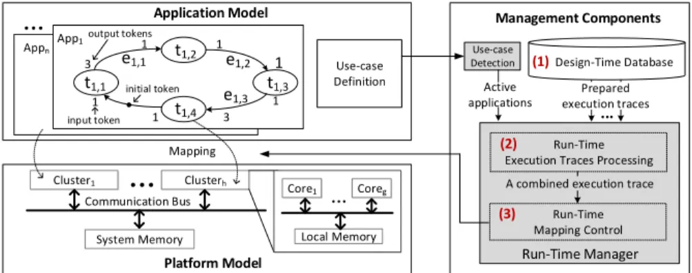
3.1 Application and Use-case Models
In this work, we consider periodic applications. An application, as illustrated in
Fig.1, is characterized by a directed task graph GAppi = (TAppi, EAppi), where
TAppi is the set of tasks of the application and EAppi is the set of directed
edges representing dependencies among the tasks. Tasks and edges in Appi are
respectively denoted by ti,jand ei,h, where j is the number of the task and h the
number of the edge. A task represents an atomic, non-preemptive, code which execution time can vary over time according to processed data. In this paper,
we restrict to periodically executed applications and each application Appi shall
be executed within its period time P eriodAppi.
In the scope of this work, applications follow the synchronous data flow (SDF) semantics that was proposed in [7]. In Fig. 1 input tokens define the number of tokens that are read from the edge before executing a task and the output token defines the number of tokens that are written through the edge after executing the task.
The set of simultaneously active applications defines a use-case uci= {App1,
App2· · · , Appn}. Let U C = {uc1, uc2, . . . , ucl} be the set of all possible
use-cases. As we consider a dynamic execution scenario, different use-cases are active over time. This information is defined in the Use-case Definition in Fig.1.
Use-case Definition Platform Model Application Model Cluster1 Clusterh System Memory Core1 Coreg Local Memory
…
… t1,2 3 3 1 1 1 1 1 1 t1,1 t1,4 t1,3 e1,1 e1,2 e1,3 App1 Appn…
Run-Time Mapping Control Run-Time Manager Mapping Run-TimeExecution Traces Processing Communication Bus
A combined execution trace Design-Time Database ... Prepared execution traces Management Components Use-case Detection input token output tokens (1) (2) (3) Active applications initial token
Fig. 1. System models with application, platform and management components de-scriptions.
3.2 Platform Model
This work targets heterogeneous cluster-based platforms, where each cluster con-sists of a set of homogeneous processing elements associated with a shared mem-ory (see Fig.1). The cores within a cluster have the same voltage/frequency (v/f ), and each cluster supports its own ranges of discrete v/f levels. One ex-ample of such platforms is the Samsung Exynos 5422 [1] with an ARM big.Little multicore architecture.
According to the platform model, we can define CommT imeei,h as the
com-munication time between dependent tasks via the edge ei,h. Similarly, the
com-putation time of a task ti,j executed on a specific cluster C at a given v/f
level is defined as CompT imeti,j(C, v/f ). Additional power model can also be
integrated in this approach (see the approach evaluation in Section 5).
3.3 Management Components
Application mapping defines the binding of application tasks to the architecture resources. As illustrated in Fig. 1, we consider run-time management in three steps: (1) a design-time preparation, (2) run-time mapping processing and (3) run-time mapping control.
In the design-time preparation step, one or several mappings for each appli-cation are prepared and stored in a database. Run-time mapping processing is performed when a new use-case is detected (Use-case Detection). In this step, a run-time mapping is established based on a particular algorithm (under eval-uation) and, as defined in [11], on the analysis of design-time execution traces of every active application in the detected use-case. Afterwards, the third step introduces a new simulation approach to control the execution of active tasks during system simulation based on the mapping established in the previous step.
4
Run-Time Mapping Modeling and Simulation Method
In this section, the proposed three steps: design-time preparation, run-time map-ping processing and a new simulation approach control for run-time mapmap-pings are detailed.
4.1 Design-Time Database preparation
The first step of most of dynamic resource managers is the design-time prepa-ration. This step consists in storing into a database a set of prepared mappings, one or several for each application. The prepared mappings can be obtained by any design-time mapping algorithm.
In our approach, a mapping is characterized by its execution trace, i.e a set
of instants defining the start (xs) and end time (xe) of each task when executed
within one possible set of platform configurations (processing element, v/f , · · ·). Only the instants within a period are prepared for a design-time mapping.
To describe the execution trace of the design-time prepared mappings, lets
consider that only one mapping is prepared for each application in A = {App1, App2}.
one distinct core. The prepared mappings of App1 and App2 are illustrated in Fig.21. PeriodApp1 core1 core2 core3 core4 time e1,1 e1,2 e1,2 e1,2 e1,3 e1,3 e1,3
LatencyApp1 LatencyApp2
t1,1(1)
core1
core2
time PeriodApp2
Tasks of App1 Instants of App1 Tasks of App2 Instants of App2
(a) (b) t1,2(2) t1,3(1) t1,4(1) t1,2(3) t1,2(1) t1,3(3) t1,3(2) t2,1(1) t2,2(1) e2,1 e1,1 e1,1
Fig. 2. A design-time prepared execution trace for the mapping of App1 (a) and App2 (b) on homogeneous cores, according to [13].
Let XAppi = {xs ti,j(1), xe ti,j(1), · · · xs ti,j(k), xe ti,j(k)}, j ∈ N
+
, k ∈ N+ be
the execution trace of Appi where k refers to the kth instance of a task. As an
example, execution traces for applications App1 and App2 in Fig.2 are
respec-tively defined by XApp1 = {xs t1,1(1), xe t1,1(1), · · · , xs t1,4(1), xe t1,4(1)}, and
XApp2 = {xs t2,1(1), xe t2,1(1), xs t2,2(1), xe t2,2(1)}.
Start and end instants xs and xe are expressed according to dependencies
between tasks. In the example given by Fig.2, dependencies of task t2,1 for
in-stance, are expressed as follows: xs t1,2(1) = xe t1,1(1) + CommT imee1,1(1) and
xe t1,2(1) = xs t1,2(1) + CompT imet1,2(1). For sake of clarity, communication
time of edges are not illustrated in next figures. Finally, LatencyApp1 refers to
the time duration for the execution of App1 from the input to the last instant
within one period. It has to be noticed that the instants here are relative as
CompT imeti,j(k) and CommT imeei,j(k) will depend on the real mapping
de-termined at run-time in the next step.
4.2 Run-Time Execution Traces Processing
The second step concerns the processing of run-time execution traces. This step
is performed each time a new use-case uci is detected. The objective is to obtain
at run-time a combined execution trace of the n active applications in the use-case uci defined by XApps0 (uci).
To obtain XApps0 (uci), the design-time prepared execution traces of each
ac-tive application (XAppi) are combined according to a given algorithm (different
mapping combination strategies can be used). In the following, we denote the process of combining execution traces by /processing. Fig.3 gives an example of one possible combined execution trace of applications on homogeneous cores of
use-case uc1= {App1, App2}. In this example the LASP (Longest Available Slot
Packing) strategy presented in [13] has been used. According to this example,
XApps0 (uc1) = /processing{XApp1, XApp2}, and it includes all the execution
in-stants, from xsof the first task, to xeof the last task in a least common multiple
LCM of periods, for the active applications in uc1.
1
As can be seen in Fig. 2, t1,2 and t1,3are executed three times for each iteration of App1. App2 is a 2-task application
core1 core2 core3 time PeriodApp2 PeriodApp1 or LCM PeriodApp2 Tasks of App1 Tasks of App2 Instants of App1 Instants of App2 t1,1(1) t1,2(2) t1,3(1) t1,4(1) t1,2(3) t1,2(1) t1,3(3) t1,3(2) t2,1(1) t2,2(1) t2,1(2) t2,2(2)
LatencyApp2 LatencyApp2
Fig. 3. A run-time combined execution trace XApps0 (uc1) using strategy in [13]. In LASP, the instances of a task are always mapped into the same core
through periods (task’s instances t2,1(1) and t2,1(2), allocated on core2, are an
example). Due to this, once the execution traces are combined, the start time of
t2,1(2) (i.e. xs t2,1(2)) is adjusted and delayed in order to start after the previous
task allocated into core2 (i.e., starting instant dependency on xe t1,2(3)). The
adjusted instants increase the LatencyApp2 of the second period. In X
0
Apps(uc1) the instants are now absolute and computed according to the active mapping.
4.3 Run-Time Mapping Control
In our approach, the run-time mapping simulation, handled by the Run-Time Manager (RTM), aims to control the execution of tasks according to the informa-tion provided by the run-time execuinforma-tion traces processing (see in Subsecinforma-tion 4.2). The proposed simulation approach is depicted in Fig.4 through the previously
used example of uc1= {App1, App2}.
The RTM is activated each time a new use-case is detected. As illustrated
in Fig.4, when uc1 is detected, the /processing step is performed to determine
the run-time mapping and dependencies of each task instance (XApps0 (uc1)). The
execution of the /processing action is done in zero simulation time with no call to the simulation kernel. The simulated effort of the RTM to perform this step depends on the used mapping strategy. The RTM then controls the states of each task according to the processed results.
/wait(wt) t1,1 t1,2 t1,3 t1,4 t2,1 t2,2 ... ... ... ... ... RTM Simulation time Start Instant Stop Instant ... Results of /processing() in uc1 ... : t1,1 start time ...
...
...
... ... ... ... ... ... ... ... ... : t2,1 start time : t1,1 end time : t2,1 end time : t2,1 start time /processing ... /processing ... Results of /processing() in uc2 ... /wait(wt) /wait(wt)Fig. 4. System-level approach for the simulation of run-time mapping strategies through the dynamic control of the execution of tasks for different use-cases.
In Fig. 4, at the simulated instant xs t1,1(1), t1,1(1) and t1,2(1) are started.
The RTM inserts some simulation delays through action /wait(wt) to wait for the next instant. Simulation time SimT ime moves forward SimT ime =
SimT ime + wt. As the next instant is xe t1,1(1), the waiting duration wt is
ex-pressed as wt = xe t1,1(1) − xs t1,1(1). After this time, t1,1(1) is stopped. As for
task instances , xs t1,2(1), xs t1,2(2) and xs t1,2(3), the RTM detects when several
instances of the same task execute successively on the same processing core. In
this case, only the first instance (xs t1,2(1)) is started and last instance xs t1,2(3)
is stopped. This further reduces the activity of the simulation effort. This pro-cess is repeated for all the task instances in every LCM period. When a new use-case is detected, the RTM performs the dynamic control for the tasks in the
new use-case (e.g. XApps0 (uc2)).
It is worth noting that this approach allows as well the evaluation and sim-ulation of run-time mapping strategies in a heterogeneous platform (different processing cores, different v/f levels, · · · ). In this case, the waiting time wt is dynamically adapted to the varying values of the computation and the
commu-nication time (CompT imet and CommT imee), according to the heterogeneous
resources configuration. An evaluation of the proposed run-time mapping control within a heterogeneous platform is presented in Section 5.
5
Evaluation of the modeling and simulation approach
5.1 Simulation Environment
We use the industrial modeling and simulation framework Intel CoFluent Stu-dio [2] to validate the proposed approach. Once again, our proposal does not need any modification in the used framework and thus can be used in other environments.
In the CoFluent framework, each application is modeled graphically with sev-eral functions (i.e., tasks) and communications (i.e., edges). For each function and communication, the computation/communication time and power consump-tion can be set by considering the influence of the platform. The built system model is then generated as a SystemC description for further execution analysis. In our implementation, the run-time manager model is captured graphically and can be considered as a specific function of the system. The implementation of the action processing corresponds to the call to a C++ code that is developed
to manipulate the previously defined data structures XAppi and XApps0 .
During the simulation, the run-time manager controls the states of each func-tion and the advancement of simulafunc-tion time according to the combined execu-tion trace. Elementary procedures available in the used framework (start, stop, resume, wait) are used by the run-time manager to control the state of the func-tions. In the following, we evaluate the influence of this run-time manager model on the effort required for the system simulation.
5.2 Simulation Setup
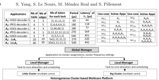
In the case study, we aim to illustrate how the proposed modeling and simulation approach is applied to a heterogeneous architecture. The organization of the evaluated system is presented in Fig.5.
Little Cluster (multiple cores) Big Cluster (multiple cores)
Local Manager Local Manager
Global Manager
Heterogeneous Cluster-based Multicore Platform Application-to-cluster assignments, cluster frequency settings
Task-to-core allocation and scheduling
Active Apps Use-case A3 A1A2 A1A2A3 A1A2A3A4 A1 A1A2A3A4A5 Active Apps Use-case A7 A6A7 A5A6A7 A4A5A6A7 A3A4A5A6A7 A2A3A4 A1A2A3 A5A6A7 A4A5A6A7 Applications A1: H263-decoder.S A2: JPEG-decoder.S A3: H263-decoder.L A4: JPEG-decoder.L A5: H263-encoder Nb of tasks Nb of token for each task
4 5 4 6 6 {1,11,11,1} {1,66,66,1} {1,6,6,6,6,1} {1,12,12,12,12,1} {1,5,5,1,1} Period (µs) 60 180 540 270 180 Nb of edges 4 Latency2 of A6: A7: 20 40 19 39 10x{1,11,11,1}5x{1,11,11,1} 270 540 XAi (µs) 5xA1 10xA1 44 118 77 164 451 220 441 3 3 5 5
Task-to-core allocation and scheduling
Fig. 5. Evaluated hierarchical run-time management of multiple applications executed on a heterogeneous cluster-based platform.
We considered H263 decoder, JPEG decoder and H263 encoder multimedia
applications and two synthetic applications. Each application Ai, has been
cap-tured as an SDF model, based on the descriptions provided in SDF3 [3]. A1
and A3 (respectively A2 and A4) are set to consume different tokens sizes for
processing at different data exchanging speed. The first five applications are representatives and require different computation time and power. To evaluate
the scalability of the proposed simulation approach, A6 and A7 are arbitrarily
created to significantly increase the number of tasks. They were created by
du-plicating A15 and 10 times respectively, while the iterations execute successively
in one period. Each application is constrained by a predefined period. For further evaluation, in the following, 13 possible use-cases are defined by different active applications (seen on top right part of Fig.5). The duration of each use-case is not depicted in the figure for the sake of clarity.
We choose the Samsung Exynos 5422 [1] platform as hardware target. As summarized in [4], the computation time of a task presents a ratio of 1 : 0.5 when executed on the little (Cortex-A7) or the big (Cortex-A15) cluster. Besides, the ratio of power consumption of a task executed on the little cluster and the big cluster is set to 1 : 4. This platform allows frequency scaling of each cluster, while the operating voltage is adapted to the frequency setting. The supported frequencies range from 0.2GHz to 1.4GHz for the little cluster, and from 0.2GHz to 2.0GHz for the big cluster. The frequency step is 0.1GHz. We use the models of Exynos 5422 in [15] to model how computation time and dynamic power consumption of tasks change with frequency.
The hierarchical managers are built to implement run-time management strategies of the system. The two local managers are individually used for each cluster to optimize task-to-core allocation and scheduling. In order to coordi-nate the local managers, the global manager determines application-to-cluster allocations and sets cluster frequencies. The management strategies are based
on design-time prepared execution traces. We establish XAifor each application
by using the strategy in [13]. For each XAi, information provided in SDF3 [3] is
used to compute the values of instants and the application latency (see Fig.5). 2
5.3 Validation of the Simulation Approach on Latency Criteria In this part, the proposed simulation approach is applied to a homogeneous architecture, where a local manager determines the task-to-core mapping inside a cluster. LASP [13] is applied to get a combined mapping of active applications in a use-case and then the latency of each application can be obtained.
0 250 500 750 1000 1250 1500 1750 2000 2250 2500 40 50 60 La te nc y (µ s) Simulation time (µs)
/processing /processing /processing /processing
PeriodA1 LatencyA1 of XA1
Fig. 6. Evolution of simulated A1latency, captured for four different use-cases. Results are given for the LASP strategy [13].
Fig.6 shows the latency evolution of A1 in four different simulated use-cases.
The simulations are performed in the little cluster at a fixed 1.4GHz cluster frequency. In this figure, the green arrows indicate the instants when a new combined execution trace is computed by /processing. For a clear illustration,
the latency of A1 is captured nine iterations for each use-case. In uc1 where
only A1 is active, LatencyA1 equals to the latency of its design-time prepared
mapping. However, LatencyA1 can be larger in uc3, uc4 and uc5. In
particu-lar, the maximum LatencyA1 in uc3 and uc4 even violate the timing constraint
P eriodA1. As discussed in Section 4.2, the increase of latency comes from the
possible delay of tasks re-allocation using the LASP combination strategy.
The latency of A1 observed in the simulation is consistent with the latency
obtained from the combined execution trace, while the combined execution trace is obtained by a run-time mapping strategy. Therefore, we can see that our simulation approach is able to correctly capture the behavior of an application under a dynamic management.
5.4 Validation of the Simulation Approach on Power Criteria
We then applied the proposed simulation approach to a heterogeneous architec-ture. In the simulated model, the global manager determines the application-to-cluster allocation and set the application-to-cluster frequencies. Different platform configura-tions lead to different computation time and different dynamic power consump-tion of a task.
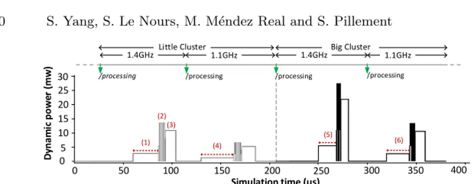
Fig. 7 shows the dynamic power consumption of A1(in uc1) under the control
of the global manager. The green arrows indicate the instants when an execution trace is adapted according to different platform configurations. In the first con-figuration (little cluster, 1.4GHz), index (1) corresponds to the active state of
t1,1. Index (2) indicates the activities of t1,2 and t1,3 that are active in parallel.
Index (3) shows the activity of task t1,4. Lets take t1,1 as an example for
fur-ther discussions. For this task, the power consumption with different platform configurations are represented in indexes (1), (4), (5) and (6), while the task
0 5 10 15 20 25 30 0 50 100 150 200 250 300 350 400 D yna m ic po w er ( mw ) Simulation time (µs) 1.4GHz 1.1GHz 1.4GHzBig Cluster 1.1GHz
/processing /processing /processing /processing
(2) (1) (3) (6) (4) (5) Little Cluster
Fig. 7. Simulated dynamic power of A1is captured with the advancement of simulation time. Results are given for uc1 according to different platform configurations.
computation time is reflected by the length of the red dotted lines. From (1) and (4), when the operating frequency decreases from 1.4GHz to 1.1GHz, the
dynamic power consumption of t1,1decreases and the task computation time
in-creases. In the case of (1) and (5), t1,1is executed at 1.4GHz on the little cluster
and big cluster respectively. The power consumption of the task observed on the big cluster is higher, while the computation time is smaller.
From the observed results in Fig.7, we can see that our approach is able to capture the behavior of an application with different platform configurations (i.e. different allocations, various v/f settings).
5.5 Evaluation of the Simulation Approach
Comparison of run-time mapping strategies: The proposed simulation approach allows the evaluation of different run-time management strategies. We compare two Local Management Strategies (LMS). LASP [13] is the first local strategy (LMS-1), which allows the task of different applications to be mapped on the same core. The second strategy (LMS-2) is the strategy introduced in [12], where only the tasks from one application can be mapped on the same core. The simulations are performed in the little cluster at 1.4GHz. In Table 1, we summarize the estimated application latency for different use-cases. As previously observed, LMS-1 leads to some increase in application latency in some use-cases.
Three Global Management Strategies (GMS) are also compared. They differ in how they allocate applications to the clusters. GMS-1 and GMS-2 denote the strategies that allocate all the active applications to the little cluster and to the big cluster respectively. GMS-3 refers to the strategy that assigns applications Table 1. Evaluation of run-time management strategies based on latency and power
Compared Critera Strategy uc1 uc2 uc3 uc4 uc5 uc6
Latency3 LMS-1 1 1 1.43 1.39 1.18 1.64 LMS-2 1 1 1 1 1 1 System Power4 GMS-1 1.68 2 1.68 1.89 1.94 2.14 GMS-2 1 1 1 1.12 1.15 1.07 GMS-3 1 1 1 1 1 1 3
Depicts the latency of the application that has the highest variation in a use-case. Each value is normalized by the latency obtained by LMS-2. 4Represents the average dynamic power of the system. Each value is
to the two clusters by searching the best power efficiency. Once the application allocation is done, cluster frequency is decreased as much as possible under the timing constraints. Then LMS-2 is used in each local manager to determine task-to-core mapping. From Table 1, we can observe the poor power efficiency of using only one cluster.
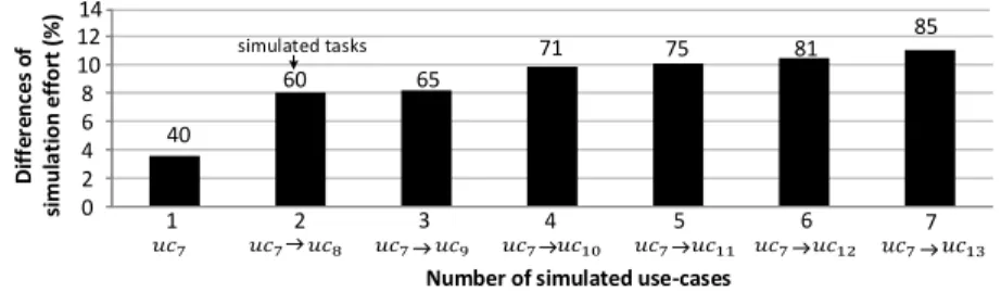
Evaluation of simulation efficiency: We analyze the scalability of the pro-posed simulation method by comparing it with the CoFluent default simulation method. The proposed approach simulates the execution of applications under the control of the Run-Time Manager model (RTM), and different mappings can be provided for each application in different use-cases. On the other hand, with-out the RTM model, the default simulation approach only provides one static mapping of the applications in every use-case. Fig.8 shows the differences in the simulation effort between the two approaches. Simulation effort is characterized by the average time needed to complete one simulation run. The results include the execution traces processing and mapping control overheads.
0 2 4 6 8 10 12 1 D if fe re nc es o f si mul a ti on ef for t (%)
Number of simulated use-cases
2 3 4 5 6 7 14 40 60 65 71 75 81 85 simulated tasks
Fig. 8. The differences of simulation effort between the proposed approach and the default approach. Results are given for an increasing number of simulated use-cases and running tasks.
We define an increasing number of running use-cases within a fixed dura-tion of simuladura-tion time, allowing each applicadura-tion to execute 100 to 240 periods. When the number of simulated use-cases increases from 1 to 7, the number of considered tasks increases from 40 to 85, while the difference of the simulation effort increases only from 3.8% to 10.8%. Since the proposed approach dynami-cally starts or stops the execution of tasks during simulation, it is reasonable to use more time to finish a simulation. But this overhead is also due to the fact that our approach takes into account the run-time manager in simulation while the default approach considers a static mapping (requiring eventually more corner-cases study). The improvement of the proposed simulation approach could be considered to reduce the dynamic activity of the run-time manager model.
6
Conclusion
In this paper, we present an approach to allow system-level simulation of run-time management strategies in multicore systems. This approach could be used to consider different numbers of applications executed on heterogeneous archi-tectures at varied v/f configurations. It has been observed that the influence of the proposed approach on the simulation effort is reasonable (less than 10.8%
compared to the default Cofluent framework for 85 running tasks). In the future, we plan to work on reducing the simulation effort of the proposed approach.
References
1. Exynos 5 octa (5422). Available:http://www.samsung.com/exynos. 2. Intel cofluent studio. Available:http://www.intel.com/.
3. Sdf3. Available:http://www.es.ele.tue.nl/sdf3.
4. A. Butko, F. Bruguier, D. Novo, A. Gamati´e, and G. Sassatelli. Exploration of performance and energy trade-offs for heterogeneous multicore architectures. arXiv preprint arXiv:1902.02343, 2019.
5. Andreas Gerstlauer, Christian Haubelt, Andy D Pimentel, Todor P Stefanov, Daniel D Gajski, and J¨urgen Teich. Electronic system-level synthesis method-ologies. IEEE Transactions on Computer-Aided Design of Integrated Circuits and Systems, 28(10):1517–1530, 2009.
6. IEEE computer society. IEEE standard SystemC language reference manual. IEEE Std. 1666–2011, 9 2011.
7. E. A. Lee and D. G. Messerschmitt. Static scheduling of synchronous data flow pro-grams for digital signal processing. IEEE Transactions on Computers, C-36(1):24– 35, Jan 1987.
8. Paul Lieverse, Pieter Van Der Wolf, Kees Vissers, and Ed Deprettere. A methodol-ogy for architecture exploration of heterogeneous signal processing systems. Jour-nal of VLSI sigJour-nal processing systems for sigJour-nal, image and video technology, 29(3):197–207, 2001.
9. A. Pimentel, C. Erbas, and S. Polstra. A systematic approach to exploring em-bedded system architectures at multiple abstraction levels. IEEE Transactions on Computers, 55(2):99–112, 2006.
10. W. Quan and A. Pimentel. A hybrid task mapping algorithm for heterogeneous mpsocs. ACM Transactions on Embedded Computing Systems (TECS), 14(1):14, 2015.
11. A.K. Singh, P. Dziurzanski, H.R. Mendis, and L.S. Indrusiak. A survey and com-parative study of hard and soft real-time dynamic resource allocation strategies for multi-/many-core systems. ACM Computing Surveys (CSUR), 50(2):24, 2017. 12. Amit Kumar Singh, Akash Kumar, and Thambipillai Srikanthan. A hybrid strat-egy for mapping multiple throughput-constrained applications on MPSoCs. In Proceedings of the 14th international conference on Compilers, architectures and synthesis for embedded systems, pages 175–184. ACM, 2011.
13. Amit Kumar Singh, Muhammad Shafique, Akash Kumar, and J¨org Henkel.
Re-source and throughput aware execution trace analysis for efficient run-time map-ping on mpsocs. IEEE Transactions on Computer-Aided Design of Integrated Cir-cuits and Systems, 35(1):72–85, 2016.
14. Andreas Weichslgartner, Stefan Wildermann, Deepak Gangadharan, Michael Glaß, and J¨urgen Teich. A design-time/run-time application mapping methodology for predictable execution time in mpsocs. ACM Transactions on Embedded Computing Systems (TECS), 17(5):89, 2018.
15. H. Zahaf, A. Benyamina, R. Olejnik, and G. Lipari. Energy-efficient scheduling for moldable real-time tasks on heterogeneous computing platforms. Journal of Systems Architecture, 74:46–60, 2017.

![Fig. 6. Evolution of simulated A 1 latency, captured for four different use-cases. Results are given for the LASP strategy [13].](https://thumb-eu.123doks.com/thumbv2/123doknet/8089381.271341/10.918.251.669.278.419/evolution-simulated-latency-captured-different-cases-results-strategy.webp)