Pépite | Contribution à la modélisation cinématique et au contrôle de manipulateurs déformables, fondée sur la mécanique numérique
145
0
0
Texte intégral
(2) Thèse de Thor Morales Bieze, Lille 1, 2017. © 2017 Tous droits réservés.. lilliad.univ-lille.fr.
(3) Thèse de Thor Morales Bieze, Lille 1, 2017. Contribution to Kinematic Modeling and Control of Soft Manipulators using Computational Mechanics Abstract: This work provides new methods for the kinematic modeling. and control of soft, continuum manipulators based on the Finite Element Method. Contrary to the case of rigid manipulators, soft and continuum manipulators generate their motion by deformation, therefore, the proposed methodology accounts for the deformation mechanics to better describe the kinematics of these type of robots. This methodology does not produce analytic solutions, instead, a numerical approximation is provided by methods derived from Computational Mechanics. The methodology is applied to a continuum manipulator, namely, the Compact Bionic Handling Assistant (CBHA). A closed-loop control scheme based on control allocation is also presented. The models and controller are validated experimentally.. Keywords: Continuum manipulators, Finite Element Method, Con-. tinuum kinematics, Continuum manipulator control, Soft robots, Continuum Mechanics, Computational Mechanics. © 2017 Tous droits réservés.. lilliad.univ-lille.fr.
(4) Thèse de Thor Morales Bieze, Lille 1, 2017. © 2017 Tous droits réservés.. lilliad.univ-lille.fr.
(5) Thèse de Thor Morales Bieze, Lille 1, 2017. iii. To my parents, Jessica and Jose Luis, for teaching me that a man, with love, can fly.. © 2017 Tous droits réservés.. lilliad.univ-lille.fr.
(6) Thèse de Thor Morales Bieze, Lille 1, 2017. © 2017 Tous droits réservés.. lilliad.univ-lille.fr.
(7) Thèse de Thor Morales Bieze, Lille 1, 2017. v. All models are wrong, but some are useful. George E. P. Box. © 2017 Tous droits réservés.. lilliad.univ-lille.fr.
(8) Thèse de Thor Morales Bieze, Lille 1, 2017. © 2017 Tous droits réservés.. lilliad.univ-lille.fr.
(9) Thèse de Thor Morales Bieze, Lille 1, 2017. vii. Acknowledgments First, I would like to dedicate this manuscript to my parents, Jessica Bieze and Jose Luis Morales, who never forget to send me their love every day, and to my three sisters Luisa, Jessica and Melissa. I would like to thank my two supervisors, Rochdi Merzouki and Christian Duriez for believing in me. Thank you for your guidance and for sharing your knowledge and wisdom with me. I could not have better mentors and for that, I will be forever grateful. I would like to thank also Jeremie Dequidt for being my friend and making my stay in the team so nice. Thanks also for being an example of how to dress well and promoting acceptable fashion in the team. Many thanks to Alexandre Kruszewski for all the help he provided during the writing of this manuscript despite the crazy deadlines and for making me feel dumb every time we talk about automatic control because that pushes me to keep learning. Many thanks to Pr. Gilberto Gonzales for pushing me to go out of my comfort zone and for caring always for my well being. Thanks to him for getting me involved in research in the beginning. Many thanks to the members of DEFROST team, Frederick Largilliere, Mario Sanz Lopez, Eulalie Coevoet, Olivier Goury, Maxime Thieffry, Zhongkai Zhang, Bruno Carrez, Erwan Douaille, Marwa ElDiwiny, Piyush Jain, Damien Marchal, Sébastien Nelissen and Félix Vanneste for being alongside me in this adventure, thank you for your support, your patience and for laughing at my bad jokes. I will carry you all in my heart. Many thanks to Anne Rejl, for all the help with the administrative nightmare. Many thanks to Sandra Hage Chehade and Camille Lihouck for giving me the opportunity to supervise their internships during their stay at INRIA and many thanks to all the students of the Bio-Inspired robotics lectures at Polytech Lille for being so receptive and patient towards me as a first time lecturer. Many thanks to all the members of MOCIS team, in particular to Othman Lakhal and Achille Melingui for all their help in the experimental validation of my work. Many thanks to the reviewers of my manuscript and jury members. I would like to thank my dear friends Moises Vazquez and Missrraim Alvarez for all the years of friendship and for sending me the "good vibes" all the way across the Atlantic. Last but not least, I would like to thank my girlfriend Marion Blasquez for her infinite love and patience and for becoming my family and giving me a loving home. She made this work possible and therefore, it is also hers.. © 2017 Tous droits réservés.. lilliad.univ-lille.fr.
(10) Thèse de Thor Morales Bieze, Lille 1, 2017. viii Finally, I want to thank my cat Brisby for keeping me company during the nights while writing this manuscript.. © 2017 Tous droits réservés.. lilliad.univ-lille.fr.
(11) Thèse de Thor Morales Bieze, Lille 1, 2017. ix. Acronyms AM API CAD CBHA CC CGAL CPU DoF FBG FEM FKM HA IKM KSI LMI ME PDE PI QP RMSD SOFA W-LAN -. © 2017 Tous droits réservés.. Additive Manufacturing Application Programming Interface Computer Assisted Design Compact Bionic Handling Assistant Constant Curvature (model) Computational Geometry Algorithms Library Central Processing Unit Degrees of Freedom Fiber Bragg Grating Finite Element Method Forward Kinematic Model Hybrid Approach (model) Inverse Kinematic Model Kinetic Sciences Inc. Linear Matrix Inequality Maximum Error Partial differential Equation Proportional Integrative (controller) Quadratic Programming Root-Mean-Square Deviation Simulation Open Framework Architecture Wireless Local Area Network. lilliad.univ-lille.fr.
(12) Thèse de Thor Morales Bieze, Lille 1, 2017. © 2017 Tous droits réservés.. lilliad.univ-lille.fr.
(13) Thèse de Thor Morales Bieze, Lille 1, 2017. xi. Glossary. © 2017 Tous droits réservés.. at C da db e E Edef F Fext Fe g G h H Ha He Hs Jea Jsa ˆsa J ˆ+ J sa. -. k ki kp K Ke m M M n pdes pef f P S u ue. -. Area of triangle Stiffness tensor Direction after cable guide Direction before cable guide System error Young’s modulus Energy of deformation Vector of internal forces Vector of external forces Vector of element loads Gravity field Shear modulus Integrative term Matrix of constraints directions Matrix of actuators constraint directions Matrix of end-effector constraint directions Matrix of sensors constraint directions Jacobian matrix between end-effector and actuators Jacobian matrix between sensors and actuators Estimated Jacobian matrix between sensors and actuators Pseudo-inverse of the estimated Jacobian matrix between sensors and actuators Spatial configuration Integrative gain Proportional gain Tangent stiffness matrix Element stiffness matrix Constant total mass Mapping function Inertia matrix Vector normal to a surface Desired position End-effector position in free configuration Position vector Set of triangles composing a cavity Displacement field Element displacement field. lilliad.univ-lille.fr.
(14) Thèse de Thor Morales Bieze, Lille 1, 2017. xii v v V W Waa Wea. -. Wsa x x˙ x ˆ. -. γ Γ δa δe. -. δs δ fa ree δ fe ree δ fs ree ΔV Δλa ε ζi λ λa λe λs φi Φ σ ω Ω. © 2017 Tous droits réservés.. -. Poisson’s ratio Closed-loop system control vector Lyapunov candidate function Compliance matrix Matrix of compliance (mechanical coupling) between actuators Matrix of compliance (mechanical coupling) between end-effector and actuators Matrix of compliance (mechanical coupling) between sensors and actuators Vector of generalized states Velocity vector Vector of estimated states. Bounding parameter Boundary surface Cable length (cable actuator) or cavity volume (pneumatic actuator) Vector representing the difference between current and desired position of end-effector Sensor string length Cable length (cable actuator) or cavity volume (pneumatic actuator) in free configuration Vector representing the difference between current and desired position of end-effector in free configuration Sensor string length in free configuration Variation of the Lyapunov function Increment of actuators contribution Infinitesimal strain tensor Tetrahedron natural coordinates Vector of constraints contributions Vector of actuator constraint contributions Vector of end-effector constraint contributions Vector of sensor constraint contributions Shape (interpolation) function associated to node i Total potential energy functional Cauchy stress tensor Vector of inversion error Three-dimensional domain. lilliad.univ-lille.fr.
(15) Thèse de Thor Morales Bieze, Lille 1, 2017. Contents 1 Introduction 1.1 General Introduction . . 1.2 Framework and context . 1.3 Motivation . . . . . . . . 1.4 Chapter summary . . . . 1.5 List of Publications . . .. . . . . .. . . . . .. . . . . .. . . . . .. . . . . .. . . . . .. . . . . .. . . . . .. . . . . .. . . . . .. . . . . .. . . . . .. . . . . .. . . . . .. 2 State of the Art 2.1 Introduction . . . . . . . . . . . . . . . . . . . . . 2.2 Continuum manipulator definition . . . . . . . . . 2.2.1 Soft continuum robot applications . . . . . 2.2.2 Bio-inspiration . . . . . . . . . . . . . . . 2.2.3 Classification . . . . . . . . . . . . . . . . 2.3 State of the art in soft, continuum manipulators . 2.3.1 Design of continuum manipulators . . . . 2.3.2 Modeling of continuum robots . . . . . . . 2.3.3 Dynamics and control of continuum robots 2.4 Work contextualization and contributions . . . . .. . . . . . . . . . . . . . . .. . . . . . . . . . . . . . . .. . . . . . . . . . . . . . . .. . . . . . . . . . . . . . . .. . . . . . . . . . . . . . . .. . . . . . . . . . . . . . . .. . . . . .. 1 1 2 2 3 4. . . . . . . . . . .. 7 7 7 8 9 10 13 13 18 27 29. 3 FEM-based model of Continuum Manipulators 3.1 Introduction . . . . . . . . . . . . . . . . . . . . . . . . . . . . 3.2 Continuum mechanics framework . . . . . . . . . . . . . . . . 3.2.1 Constitutive material law . . . . . . . . . . . . . . . . 3.2.2 Forces in the continuum manipulator . . . . . . . . . . 3.3 Finite Element Method . . . . . . . . . . . . . . . . . . . . . . 3.4 FEM-based kinematics of soft manipulators . . . . . . . . . . 3.4.1 Constraint for the end-effector . . . . . . . . . . . . . 3.4.2 Actuator constraint model . . . . . . . . . . . . . . . . 3.4.3 Sensor constraint model . . . . . . . . . . . . . . . . . 3.5 Reduced model in the constraint space . . . . . . . . . . . . . 3.5.1 Reduced compliance on the constraint space . . . . . . 3.5.2 Coupled Kinematic Equations . . . . . . . . . . . . . . 3.5.3 Inverse kinematic model solution by convex optimization 3.6 Method implementation . . . . . . . . . . . . . . . . . . . . . 3.6.1 Simulation framework . . . . . . . . . . . . . . . . . . 3.6.2 Corotational FEM . . . . . . . . . . . . . . . . . . . . 3.6.3 Mesh generation . . . . . . . . . . . . . . . . . . . . .. © 2017 Tous droits réservés.. 31 32 33 34 35 36 38 39 41 44 45 45 47 48 49 50 50 51. lilliad.univ-lille.fr.
(16) Thèse de Thor Morales Bieze, Lille 1, 2017. xiv. 3.7. 3.8. Contents 3.6.4 Description of the Compact Bionic Handling Assistant 3.6.5 Simulation of the CBHA . . . . . . . . . . . . . . . . . Kinematic models . . . . . . . . . . . . . . . . . . . . . . . . . 3.7.1 Forward kinematic models . . . . . . . . . . . . . . . . 3.7.2 Inverse kinematic model . . . . . . . . . . . . . . . . . Conclusion of the chapter . . . . . . . . . . . . . . . . . . . .. 4 Closed loop control of soft, continuum manipulators 4.1 Introduction . . . . . . . . . . . . . . . . . . . . . . . . 4.2 Feed-forward control of continuum manipulators . . . . 4.3 Closed-loop control of continuum manipulators . . . . . 4.3.1 Closed-loop control law design . . . . . . . . . . 4.3.2 Robustness analysis . . . . . . . . . . . . . . . . 4.4 Conclusions of the chapter . . . . . . . . . . . . . . . .. 51 53 55 56 62 63. . . . . . .. 67 67 68 71 72 76 80. 5 Conclusion and Perspectives 5.1 Summary of conclusions . . . . . . . . . . . . . . . . . . . . . 5.2 The FeTCh manipulator . . . . . . . . . . . . . . . . . . . . . 5.3 Perspectives . . . . . . . . . . . . . . . . . . . . . . . . . . . .. 83 83 85 88. A Introduction to Continuum Mechanics and FEM A.1 Introduction . . . . . . . . . . . . . . . . . . . . . . A.1.1 Continuum Mechanics . . . . . . . . . . . . A.2 Finite Element Method for linear elastic bodies . . A.2.1 Discretization of the domain . . . . . . . . . A.2.2 Element solution . . . . . . . . . . . . . . . A.2.3 Assembly . . . . . . . . . . . . . . . . . . . A.2.4 Displacement boundary conditions . . . . . A.2.5 Solution method . . . . . . . . . . . . . . .. . . . . . . . .. . . . . . . . .. . . . . . .. . . . . . . . .. . . . . . .. . . . . . . . .. . . . . . .. . . . . . . . .. . . . . . . . .. 89 89 89 98 99 100 103 105 106. B Domain decomposition of continuum manipulators 109 B.1 Domain decomposition of the CBHA . . . . . . . . . . . . . . 109 Bibliography. © 2017 Tous droits réservés.. 111. lilliad.univ-lille.fr.
(17) Thèse de Thor Morales Bieze, Lille 1, 2017. Chapter 1. Introduction. Contents. 1.1. 1.1. General Introduction . . . . . . . . . . . . . . . . . . .. 1. 1.2. Framework and context . . . . . . . . . . . . . . . . . .. 2. 1.3. Motivation. . . . . . . . . . . . . . . . . . . . . . . . . .. 2. 1.4. Chapter summary . . . . . . . . . . . . . . . . . . . . .. 3. 1.5. List of Publications . . . . . . . . . . . . . . . . . . . .. 4. General Introduction. 50 years after the construction of the first continuum manipulator, researchers and engineers still consider the modeling and control of this type of robot an open problem. The development of a generic modeling approach for continuum manipulators that can capture the main behavior characteristics regardless of its design seems like a far fetched idea. From our point of view, this issue is linked to some key factors. First, the bio-inspiration behind continuum manipulators: nature offers a myriad of shapes and motion mechanisms from which we can gather inspiration for the design of soft, continuum manipulators. However, most of these principles require a great insight of the biological object of inspiration. As we close the gap between the more traditional rigid designs of manipulators currently populating the factories and the organic bodies of snakes and tentacles, the need to trespass the knowledge boundaries of robotics as a field arises. On the other hand, the tools used to study this type of robots usually aim at the over-simplification of the problem; as for the writing of this manuscript, the most popular approach towards the modeling of continuum manipulators is based on conventional rigid robotic methodologies that consider only the structural geometry of the robot as an important feature in the modeling. In reality, the geometrical description of the manipulator is only one part of. © 2017 Tous droits réservés.. lilliad.univ-lille.fr.
(18) Thèse de Thor Morales Bieze, Lille 1, 2017. 2. Chapter 1. Introduction. the solution to the kinematic model. The other part being the continuum deformation. In the study of deformations of continuum bodies, the field of continuum mechanics appears as a natural choice of analysis framework. In our opinion, a generic modeling methodology for continuum manipulators should be based on continuum mechanics since it allows for an accurate approximation of the kinematic solution based on a constitutive material law. If the material of the manipulator changes, it is only this constitutive law that changes in the model, but not its entire formulation.. 1.2. Framework and context. This Ph.D. thesis was developed within the research groups, Deformable Robotic Software (Defrost)1 from Inria Lille-Nord Europe and Méthodes et Outils pour la Conception Intégrée de Systémes (MOCIS), of the Centre de Recherche en Informatique, Signal et Automatique de Lille (CRIStAL) (UMR CNRS 9189)2 . The implementation of the Ph.D. results has been realized as part of the framework of technological research with Festo-Didactic company from Essligen, Germany 3 . This Ph.D. was funded by the Mexican National Council of Science and Technology (CONACYT) 4 .. 1.3. Motivation. A generic modeling and control approach needs to have modularity. We need to be able to include, for example, the contact computation or the environment interaction with the robot as a module in our model to give it re-usability. It is simply not practical to think about a re-calibration of the model every time the conditions of operation change. To this end, this Ph.D. work proposes a modeling and control methodology for soft, continuum manipulators based on computational mechanics. At the core of this methodology is the Finite Element Method (FEM), a technique for the approximation of differential equations with boundary conditions. FEM is used in this context to discretize the theoretical infinite number of degrees of 1. https://team.inria.fr/defrost/ https://www.cristal.univ-lille.fr/ 3 http://www.festo-didactic.com/int-en/ 4 http://conacyt.gob.mx/ 2. © 2017 Tous droits réservés.. lilliad.univ-lille.fr.
(19) Thèse de Thor Morales Bieze, Lille 1, 2017. 1.4. Chapter summary. 3. freedom of continuum manipulators. The imposition of constraints in the form of Lagrange Multipliers allows for the model of sensors, actuators and endeffector. In this way, the forces applied to the manipulator by the actuators are related to the end-effector and sensors spaces. Forward and inverse kinematic models are derived from the FEM model of the manipulators. To account for non-modeled nonlinear behaviors of the robot, a closed-loop control strategy based on the implementation of the simulation as a state estimator is proposed.. 1.4. Chapter summary. The manuscript is organized in 4 chapters as follows: Chapter 2 introduces the definition of the kinematic model of continuum manipulators. To this end, the challenges of modelization are identified. The current state of the art in kinematic models and the methods used are given, along with the most recent efforts towards the formalization of a design methodology and control of continuum manipulators. The proposed methodology is then positioned in the context of the literature. Chapter 3 formally introduces the methodology. First, a brief introduction to Continuum Mechanics is given and the fundamental steps of the Finite Element method are presented. Then, the method of modeling of continuum manipulators based on Computational Mechanics is explained. The concept of constraints, fundamental in the development and application of the method, is introduced. Also, in this chapter we talk about the simulation framework used for the implementation of the method and the general steps required to obtain a robot simulation. Then, the method is applied to a continuum manipulator, namely, the Compact Bionic Handling Assistant (CBHA). The kinematic relationships between 3 different spaces are explained and the experimental validation for forward and inverse kinematics is shown. The objective of Chapter 4 is to present a closed-loop control strategy for continuum manipulators based on the methodology given in the previous chapters. The feed-forward control strategy based on real-time simulation is showcased and, based on the experimental results, we explain the need for more accurate controllers. The closed-loop control based on PI control law and control allocation based on Quadratic Programming (QP) formulation is proposed. The implementation of the controller is validated with experiments. © 2017 Tous droits réservés.. lilliad.univ-lille.fr.
(20) Thèse de Thor Morales Bieze, Lille 1, 2017. 4. Chapter 1. Introduction. using the CBHA and the robustness analysis for the close-loop system is also performed. Finally, Chapter 5 gives the conclusions for this work and discuss the perspectives of future work, in particular, the use of the methodology towards the design of soft, continuum manipulators based on simulation and possible improvements to the model of this type of robots.. 1.5. List of Publications. The results obtained during the development of this work have made the topic of the following list of publications: Journal Publication • Bieze T., Largilliere F., Merzouki R., Duriez C. (Under review). FEMbased forward and inverse kinematics of soft, continuum manipulators. Soft Robotics Journal. Submitted on June 2017. • Coevoet E., Bieze T., Largilliere F., Zhang Z., Thieffry M., Carrez B., Marchal D., Goury O., Dequidt J., Duriez C. (Under review) Software toolkit for modeling, simulation and control of soft robots. Advanced Robotics Journal. Submitted on March 2017. International Conference • Zhang Z., Bieze T., Dequidt J., Kruszewski A., Duriez C., Visual Servoing Control of Soft Robots based on Finite Element Model. Accepted for publication in 2017 IEEE/RSJ International Conference on Intelligent Robots and Systems (IROS 2017) • Duriez, C., Coevoet, E., Largilliere, F., Bieze T., Zhang, Z., Sanz-Lopez, M., Dequidt, J. (2016, December). Framework for online simulation of soft robots with optimization-based inverse model. In Simulation, Modeling, and Programming for Autonomous Robots (SIMPAR), IEEE International Conference on (pp. 111-118). IEEE. • Lakhal, O., Melingui, A., Bieze, T. M., Escande, C., Conrard, B., Merzouki, R. (2014, December). On the kinematic modeling of a class of continuum manipulators. In Robotics and Biomimetics (ROBIO), 2014 IEEE International Conference on (pp. 368-373). IEEE.. © 2017 Tous droits réservés.. lilliad.univ-lille.fr.
(21) Thèse de Thor Morales Bieze, Lille 1, 2017. 1.5. List of Publications. 5. • Bosman, J., Bieze, T. M., Lakhal, O., Sanz, M., Merzouki, R., Duriez, C. (2015, May). Domain decomposition approach for FEM quasistatic modeling and control of Continuum Robots with rigid vertebras. In Robotics and Automation (ICRA), 2015 IEEE International Conference on (pp. 4373-4378). IEEE. Book Chapter • Duriez, C., Bieze, T. (2017). Soft Robot Modeling, Simulation and Control in Real-Time. In Soft Robotics: Trends, Applications and Challenges (pp. 103-109). Springer International Publishing. Other contributions • Runner up Prize at the Soft Robotics Toolkit Design Competition (2015). FeTCH Mark I Manipulator. Contributors: Bieze T., Largilliere F., Hage S., Sanz-Lopez M., Duriez C., Project page at https://softroboticstoolkit.com/fetch • Bieze, T. (2015). On the Kinematic Modeling Methodology of Soft Manipulator Robots. Poster presentation. In Robotics and Automation (ICRA), 2015 IEEE International Conference on. IEEE.. © 2017 Tous droits réservés.. lilliad.univ-lille.fr.
(22) Thèse de Thor Morales Bieze, Lille 1, 2017. © 2017 Tous droits réservés.. lilliad.univ-lille.fr.
(23) Thèse de Thor Morales Bieze, Lille 1, 2017. Chapter 2. State of the Art. Contents 2.1. Introduction. . . . . . . . . . . . . . . . . . . . . . . . .. 7. 2.2. Continuum manipulator definition . . . . . . . . . . .. 7. 2.3. 2.4. 2.1. 2.2.1. Soft continuum robot applications . . . . . . . . . . .. 8. 2.2.2. Bio-inspiration . . . . . . . . . . . . . . . . . . . . . .. 9. 2.2.3. Classification . . . . . . . . . . . . . . . . . . . . . . .. 10. State of the art in soft, continuum manipulators . . .. 13. 2.3.1. Design of continuum manipulators . . . . . . . . . . .. 13. 2.3.2. Modeling of continuum robots . . . . . . . . . . . . . .. 18. 2.3.3. Dynamics and control of continuum robots. . . . . . .. 27. Work contextualization and contributions . . . . . . .. 29. Introduction. In this chapter, we will, first, give a formal definition of a soft, continuum manipulator in the context of this work. The State of the Art related to the modeling, design and control of this type of robots is provided in order to position our work in the framework of the current literature.. 2.2. Continuum manipulator definition. To grasp the concept of continuum manipulator it is always helpful to visualize a conventional manipulator composed, in general, by a set of joints, rotational or spherical, serially connected by rigid links. In this class of manipulators, the links provide a kinematic relationship between the joints; in other words, by knowing the lengths of the links, one can always know the relative position of the joints with respect to a common reference frame [Siciliano 2016]. Now, let us place additional joints along the rigid links of our imaginary manipulator.. © 2017 Tous droits réservés.. lilliad.univ-lille.fr.
(24) Thèse de Thor Morales Bieze, Lille 1, 2017. 8. Chapter 2. State of the Art. Soon enough, our manipulator will have more active1 degrees of freedom than the ones required to position an object in space. In the literature, these type of manipulators are known as hyper-redundant [Hirose 2004]. If we keep repeating the process of adding joints until their number approaches infinity and the link lengths to zero, our robot will eventually approach to what is known as a continuum manipulator.. Figure 2.1: Left) A classic industrial manipulator, (Center) A hyper-redundant robot, the meeting ground between a rigid and a continuum manipulator, (Right) A continuum manipulator The previous definition may imply that all the degrees of freedom in a continuum manipulator are controllable, which is in general, not the case. Often bio-inspired by the morphology and functionality of biological limbs and appendices like octopus tentacles [Zheng 2014], elephant trunks [Neppalli 2007] [McMahan 2005] [Zhao 2010], plant tendrils [Mehling 2006] [Yamada 2014] and other mammal tongues, continuum manipulators are composed by an elongated structure with no identifiable joints, which is continuously bending via elastic deformation [Robinson 1999].. 2.2.1. Soft continuum robot applications. The characteristics of soft continuum manipulators, like their natural compliance, high power to weight ratio, and reduced dimensions compared to their 1. In robotics, the degrees of freedom can be of two types: passive degrees of freedom are the ones that cannot be directly controlled and conform passively to the movements of the robot, while active degrees of freedom are the ones that are controlled to provide the required forces to move the manipulator.. © 2017 Tous droits réservés.. lilliad.univ-lille.fr.
(25) Thèse de Thor Morales Bieze, Lille 1, 2017. 2.2. Continuum manipulator definition. 9. rigid counterparts, make them particularly suitable for applications in which the contact with humans is unavoidable or even desired. Applications such as skeletal trauma treatment [Wilkening 2017] [Alambeigi 2017], endoscopy [Conrad 2013] [Cianchetti 2013] [Fraś 2015] and minimally invasive surgery [Qu 2016] [Orekhov 2016] [Mahoney 2016] have proved the great potential of application of continuum robots in the medical field, as extensively reviewed in [Burgner-Kahrs 2015]. As suggested by the very first prototypes of continuum manipulators [Anderson 1967]. The slender shape and high dexterity of continuum manipulators can be exploited in tasks such as minimally invasive inspection [Mehling 2006] [Tonapi 2014] and search and rescue [Bajo 2010] [Li 2017]. Continuum robots have been studied with the goal of exploiting their locomotive capabilities [Godage 2012] [Kang 2012] [Arienti 2013], although the review presented in the following of this manuscript is concerned mainly on manipulation.. 2.2.2. Bio-inspiration. If one sees for the first time a continuum manipulator, without any previous knowledge on the concept behind it, one can immediately identify the remarkable morphological similarities that this type of devices have with some soft-bodied animals, particularly with the muscular hydrostats. Muscular hydrostats, commonly found in elephant trunks, mammal tongues and octopus tentacles are soft muscular structures that can bend, extend and twist and provide the force required for movement and skeletal support to animals (or limbs) that lack a rigid skeleton, see Fig. 2.2. Muscular hydrostats are typically composed by a fluid-filled cavity surrounded by a muscular wall reinforced with connective tissue fibres. The arrangement of the muscle fibres in a hydrostatic muscle include both circular and longitudinal muscle fibres. These two muscle fibres can antagonize one another to produce a variety of shape changes including elongation and bending [Kier 1992]. The fluid inside the cavity of a hydrostatic limb is mainly a liquid which resists to volume change, thus, to create an elongation of the limb, the circular muscles contract to decrease the diameter while increasing the length to allow for a constant volume inside the cavity. The study of the biomechanics of hydrostatic structures have shown also additional fibres with more intricate configuration patterns that allow for more complex shape changes like twisting, present in octopus tentacles and mammals and reptile. © 2017 Tous droits réservés.. lilliad.univ-lille.fr.
(26) Thèse de Thor Morales Bieze, Lille 1, 2017. 10. Chapter 2. State of the Art. Figure 2.2: Diagram of the hydrostatic muscle in the arm of Octopus from [Trivedi 2008b]. AN, axial nerve cord; AR, artery; CM, circumferential muscle layer; CT, connective tissue; DCT, dermal connective tissue; EP, epidermis; IN, intramuscular nerve; LM, longitudinal muscle fibres; OME, external oblique muscle layer; OMI, internal oblique muscle layer; OMM, median oblique muscle layer; SU, sucker; TM, traverse muscle fibres; TR, trabeculae; and V, vein. tongues [Kier 1985]. The complete replication of hydrostats is very complex, but the study of their underlying function principles have given roboticists an interesting insight and a solid starting point in the design of soft, continuum manipulators.. 2.2.3. Classification. Continuum manipulators can be broadly classified with respect to the type of backbone they possess. Single backbone manipulators (see Fig. 2.3 (left)) have a central elongated structure that supports the passage of actuation/transmission elements along the body of the manipulator [Burgner-Kahrs 2015]. Many single-backbone designs utilize tendons routed along the structure which are spaced by discs attached to the backbone as a way of transmission. The termination points of the tendons in this type of design dictate the lengths of a bending section. Multibackbone (Fig. 2.3 (right)). © 2017 Tous droits réservés.. lilliad.univ-lille.fr.
(27) Thèse de Thor Morales Bieze, Lille 1, 2017. 2.2. Continuum manipulator definition. 11. continuum manipulators are typically composed by a parallel arrangement of elastic elements which are constrained with respect to each other in some way.. Figure 2.3: Single and Multibackbone continuum robots:(left) A single backbone tendon-driven steerable cardiac catheter from [Camarillo 2008].(Right) The DDU multibackbone manipulator designed by Simaan et al. [Simaan 2009].. Another classification of continuum manipulators is based on the actuation system implemented to apply forces and torques to the backbone. When the actuators are embedded in the structure and apply forces directly to the backbone, the actuation scheme is called intrinsic. Most continuum robot designs with multi-backbones use pneumatic cavities to conform the structure, essentially making a backbone composed of actuators that can be reshaped by applying pressure to the cavities. Extrinsic actuation systems place the actuators outside of the structure. These apply torques and forces at localized points via a mechanical link to the backbone, which is made by an incomprehensible elastic rod. A hybrid actuation scheme replaces the central elastic rod in an extrinsic design by an actively controlled actuator, which is in many designs, a pneumatic cavity [Chirikjian 2015] [Ataollahi 2017].. © 2017 Tous droits réservés.. lilliad.univ-lille.fr.
(28) Thèse de Thor Morales Bieze, Lille 1, 2017. 12. Chapter 2. State of the Art. Figure 2.4: The KSI hybrid actuated manipulator [Immega 1995]. Figure 2.5: (Left) The Clemson tentacle, an extrinsic actuated manipulator [Gravagne 2001]. (Right) The BHA, an intrinsic actuated manipulator [Rolf 2012].. © 2017 Tous droits réservés.. lilliad.univ-lille.fr.
(29) Thèse de Thor Morales Bieze, Lille 1, 2017. 2.3. State of the art in soft, continuum manipulators. 2.3. 13. State of the art in soft, continuum manipulators. This section describes the research developed in the last 20 years, towards the design, modeling and control of soft, continuum manipulators. The review is divided into each of the subtopics mentioned in order to provide a clear overview of the field.. 2.3.1. Design of continuum manipulators. As stated in [Walker 2013a], the first prototype of a continuum robot reported in the literature was the Tensor Arm [Anderson 1967], designed by Anderson and Horn in 1967. Conceived to be used under water, the prototype was able to achieve a wide range of shapes; however, the relationship between the shapes and inputs was highly complex and challenging for the computational resources of that time. Based on extrinsic actuation, the robot used nylon filaments routed along the structure through spacer discs that apply torques directly to the backbone to produce bending, see Fig. 2.6. As is usual in tendon-based designs, the termination points of the cables define the bending sections. This prototype has inspired since then, a significant number of designs based on the same principle.. Figure 2.6: The "Tensor Arm" by Anderson and Horn [Anderson 1967]. Walker and Hanna presented the Elephant’s Trunk Robot [Walker 1999], a continuum manipulator with extrinsic actuation composed of 4 main bending sections. The robot uses a pulley system outside the structure to pull cables. © 2017 Tous droits réservés.. lilliad.univ-lille.fr.
(30) Thèse de Thor Morales Bieze, Lille 1, 2017. 14. Chapter 2. State of the Art. and bend the sections. Spacer disks are used to give the robot its characteristic shape but they also provide a mechanical coupling; out of the 32 DoF only 8 are actively controllable, leaving the rest to be coupled by passive springs positioned between adjacent segments of the manipulator at a 90 degrees angle with respect to the tendons. Thanks to this work the identification of critical hardware necessities in the field was possible, in particular the need for elastic structures. Later work in design of continuum robots replaced the spring system by an incompressible elastic rod [Gravagne 2003]. This choice of backbone has been, since then, the most used in tendon-based designs of continuum manipulators [Hemami 1984] [Simaan 2004] [Bardou 2010] [Zhao 2010]. Another choice of backbone is the use of a central spring [Mehling 2006] that provides the desired compliance to the manipulator but makes the operation of this type of manipulators a difficult task, since the forces applied by the tendons tend to be absorbed by the spring. However, spring-backbone manipulators have been implemented as actuated endoscopes with great success [Yoon 2011]. At the same time, research in the area of artificial muscle design facilitated the conception of locally actuated designs, such as the Oct-Arm [Walker 2005] [McMahan 2006], the "European Octopus" [Calisti 2012] [Guglielmino 2010] [Laschi 2009], and the Bionic Handling Assistant [Rolf 2012], which is inspired by the trunk of an elephant, with possible appealing advantages like full-body manipulation. Intrinsic design manipulators proved to be very dexterous by reproducing the way longitudinal muscles work in an animal trunk or tentacles [McMahan 2006]. Originally developed to provide actuation to a prosthesis device for severely paralyzed hand patients, the McKibben artificial muscle [Nickel 1963] has been used in continuum robot designs with great success [McMahan 2006] [Pritts 2004]. This type of pneumatic muscle is composed by a soft cavity constrained in its deformation by a braided sleeve. The muscle is considered contractor if the cavity expands radially when the pressure is increased in the cavity, or extensor if the cavity expands longitudinally. This operation is analogous to the longitudinal muscles. Experiments conducted on the McKibben muscle [Klute 1999] show that it provides a first order approximation to a biological muscle when contracting. Another venue for researchers to design extrinsic actuation is the implementation of concentric tubes as the structure of the manipulator [Sears 2006] [Gilbert 2016]. The body of the robot is composed by a telescopic array of concentric tubes that are free to rotate and translate with respect to each other. To provide bending to the robot, the tubes are often pre-curved, so that when a distal tube is translated outside of the preceding one, it will nat-. © 2017 Tous droits réservés.. lilliad.univ-lille.fr.
(31) Thèse de Thor Morales Bieze, Lille 1, 2017. 2.3. State of the art in soft, continuum manipulators. 15. Figure 2.7: (Left) Extensor and contractor pneumatic muscles, (Right) An example of a locally actuated design, the Oct-Arm manipulator composed by pneumatic muscles, from [McMahan 2006] urally bend [Furusho 2006]. Pre-curved concentric tubes designs have found a niche of applications in the medical field [Wu 2017], where their slim and clean design is well suited to act as actuated endoscopes in minimally invasive surgery [Furusho 2006] [Su 2012].. Figure 2.8: A concentric tube robot or Active Cannula composed by 3 pre-curved tubes, from [Wu 2017] Given the advantages of intrinsic actuation in terms of dexterity, particularly the ability to extend the backbone longitudinally and in turn, improve its. © 2017 Tous droits réservés.. lilliad.univ-lille.fr.
(32) Thèse de Thor Morales Bieze, Lille 1, 2017. 16. Chapter 2. State of the Art. ability to bend [Walker 2006], robot designers started to experiment with hybrid actuation schemes that incorporate both pneumatic cavities and tendons. An example of this type of design is the Air-Octor [Jones 2004a] [Jones 2004b] depicted in Fig. 2.9, a manipulator composed by a soft pneumatic hose that acts as the backbone, which is actuated by 3 cables to achieve bending. While the prototype proved to be capable of full-body manipulation, it suffered from sagging and kinking of the soft backbone cavity [McMahan 2005], a problem that is common to this type of designs. Another example of a realized hybrid actuation scheme is the KSI manipulator [Immega 1994], developed by Kinetic Sciences Inc. in 1994 [Immega 1995]. 2.3.1.1. Backbone variable stiffness. In order to exploit to the maximum the capabilities of continuum robots, the ability to variate the stiffness of its structure is needed, particularly in medical applications were excessive contact forces at the tip of the manipulator can cause severe trauma to the surrounding tissue. In the literature, one can find different approaches to the variable stiffness of the backbone. In [Mahvash 2010], a stiffness control approach is presented. The method is based on the derivation of the kinematic model of the manipulator as the product of two transformations: the first transformation describes the non contact kinematics of the manipulator and it is specific to the robot itself, while the second transformation calculates the tip deflection due to the applied forces and is derived using the Cosserat rod formulation [Mahvash 2011]. To implement a desired tip stiffness, the two transformations are used to solve for the actuator positions that deform the manipulator so as to generate the required tip force at the measured tip position. This method is applied to a concentric tube design intended for minimally invasive surgery. In [Goldman 2011] a method for the stiffness control of intrinsic actuated manipulators is presented. The proposed algorithm relies on the measurement of actuation forces, in conjunction with the stiffness of the backbone, to move in a direction to minimize the environment interaction. The combination of pneumatic backbones and tendons provide the means to increase the apparent stiffness of the structure by antagonizing the set of redundant actuators that compose the robot [Walker 2013b]. In [Maghooa 2015] the pneumatic backbone and tendons of a hybrid manipulator are controlled simultaneously to achieve a certain position of the tip of the arm while actively changing the stiffness of the robot applying the principle of antagonistic actuation. This functionality is also bio-inspired [Shiva 2016], being present in a significant number of animal arms, trunks and even the human tongue.. © 2017 Tous droits réservés.. lilliad.univ-lille.fr.
(33) Thèse de Thor Morales Bieze, Lille 1, 2017. 2.3. State of the art in soft, continuum manipulators. 17. Figure 2.9: The Air-Octor hybrid manipulator composed by a pneumatic backbone which is bent by tendons, as presented in [Jones 2004b] Some continuum manipulator prototypes utilize local rigidification mechanisms to simplify the stiffness control; such is the case of the STIFFFLOP manipulator [Cianchetti 2013] [Fraś 2015], that utilizes granular jamming [Steltz 2010], in conjunction with pneumatic cavities to achieve a certain degree of variable stiffness of the structure. Each section of the robot is composed by an elastomeric cylinder that hosts three pneumatic cavities to provide bending and extension as well as a central chamber that holds the granular media. The section is surrounded by a braided sleeve to prevent the radial deformation of the elastomeric cavities. The granular media utilized is coffee powder, which jams when the central cylinder is under negative pressure causing drastic stiffness changes of the structure [Jiang 2012]. The STIFF-FLOP is one of the most advanced continuum manipulators prototypes currently under development, having force [Noh 2014] and tactile [Sareh 2014] capabilities provided by sensors embedded in the structure of the robot. More advanced actuation systems have been studied with the intention of stiffness control. In [Sadeghi 2012], Sadeghi et al. demonstrated a method to control the stiffness of a worm-like soft robot utilizing electro-rheological materials that can change phase, from fluid to solid and vice versa, under the presence of magnetic fields.. © 2017 Tous droits réservés.. lilliad.univ-lille.fr.
(34) Thèse de Thor Morales Bieze, Lille 1, 2017. 18. Chapter 2. State of the Art. 2.3.1.2. Design methodologies. The key challenge for creating soft machines that achieve their full potential is the development of controllable soft bodies using materials that integrate sensors, actuators and computation, and that together enable the body to deliver the desired behaviour [Rus 2015]. The conception of a design methodology for continuum robots is not a trivial task due to the wide variety of possible backbone-actuation schemes, the applications to which the design is aimed at and more importantly, due to the interdisciplinary nature of the design tasks; very often, electronics, mechanics and computer science come into play during the integration of the system. Nevertheless, some design guidelines can be found in the literature. For example, a pragmatic approach to the design of continuum arms inspired by the octopus tentacle is presented in [Guglielmino 2013]. In [Bedell 2011] an algorithm for the optimization of concentric tube robot design is proposed; given the description of the task space and the number of sections in the robot, the algorithm solves for a design with the desired workspace. The fabrication of artificial pneumatic muscles is also a daunting enterprise that requires, in most cases, multiple design iterations to achieve a desired behavior. A direct2 finite element simulation has been used in [Connolly 2015] for the programming of desired deformations of pneumatic muscles with braided sleeves. The work of Hauser et al. in [Hauser 2011] presents the concept of morphological computation. This concept aims at the relegation of difficult control tasks in soft bodied robots to the body itself, making use of inherit characteristics of the robot, like the natural compliance of its structure [Paul 2006]. While it is difficult to directly design smart bodied robots, this work provides useful design guidelines compatible with any kind of bio-inspired robot [Pfeifer 2009].. 2.3.2. Modeling of continuum robots. In order to control the movement of continuum robots, kinematic models, which relate the configuration (pose) of the backbone and task space (endeffector position) and actuator variables must be established. These models are fundamental for the development of control strategies and path planning 2. In this work, we refer to the direct finite element when the unknown nodal displacement is computed given the known external forces. © 2017 Tous droits réservés.. lilliad.univ-lille.fr.
(35) Thèse de Thor Morales Bieze, Lille 1, 2017. 2.3. State of the art in soft, continuum manipulators. 19. for continuum manipulator robots. Equation (2.1) depicts the general form of a kinematic model for conventional manipulators. x = f (q). (2.1). where x is the position of the end-effector inside the task space of the robot which is, more often than not, expressed in cartesian coordinates, q is the set of configuration variables related to the joint variables (which are, in general, observable and directly controlled) and f is the unknown function that relates task space variables to the configuration of the robot. For soft, continuum robots however, f depends on the configuration variables and also on the mechanics of the deformable material. We can then rewrite Eq. 2.1 for continuum manipulators as x = f (q, ϑ). (2.2). where ϑ represents the mechanics of the soft material. The modeling task deals with finding this relationship and the assumptions used in order to accomplish this goal dictates the type or flavor of the modeling approach. In general, kinematic modeling approaches of continuum manipulators can be broadly classified as quantitative models, which deal with the description of the robots in a mathematical fashion making use of geometry and elasticity theories, and qualitative models, which are numerical abstractions of the more complex model and often make use of experimental data to find the closest solution to the kinematic problem.. Qualitative models Due to the complexity involved in the modeling of continuum robots, qualitative approaches, which aim at learning the kinematic problem by the use of learning algorithms, have a significant level of popularity due to their ability to by-pass the modeling task. These approaches are based on previous knowledge of input-output data derived from experimentation and can provide accurate fast approximations to the kinematic solutions. Rolf and Stein proposed in [Rolf 2014] a control scheme for the Bionic Handling Assistant based on goal babbling [Rolf 2010]. The control scheme is capable of dealing with highly non-linear behavior like hyperelasticity, plasticity and non-stationarities, which are very complex to address analytically. Control schemes based on Neural Networks have been also investigated. Giorelli et al. [Giorelli 2013] used a feedforward neural network to learn the in-. © 2017 Tous droits réservés.. lilliad.univ-lille.fr.
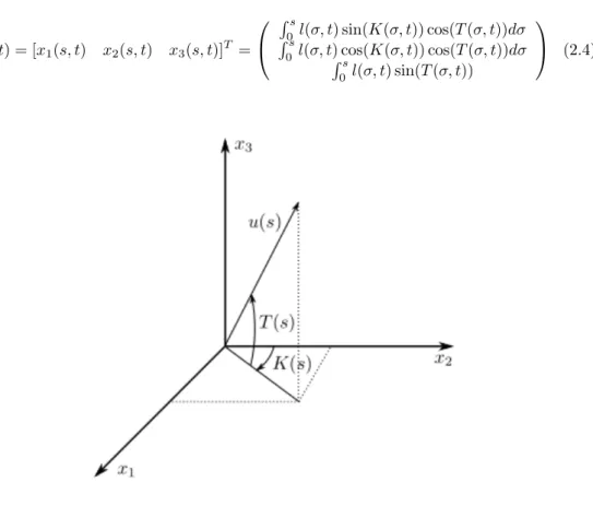
(36) Thèse de Thor Morales Bieze, Lille 1, 2017. 20. Chapter 2. State of the Art. verse kinematics of a tendon driven manipulator. In this approach, a geometrical model of the manipulator is used for data generation and in [Giorelli 2015] a controller based on the static model Jacobian is used to control a nonconstant curvature manipulator. Another feedforward neural network controller was proposed by Braganza et al. [Braganza 2006] [Braganza 2007]. In this work, no model is required; instead, a low level controller uses the neural network component to compensate for the dynamic uncertainties of the manipulator. More recently, the work of Melingui et al. [Melingui 2014] employed a neural network to solve the inverse kinematics based on the measurements of the end-effector position. In [Melingui 2017] an adaptive algorithm is implemented to improve the performance of the controller by allowing rapid position convergence of the end-effector. While qualitative controllers have shown great success in real world scenarios, the fact that the learning base changes when the operation conditions of the robot change make data-driven models limited in their application. This is the main reason as to why quantitative approaches still dominate the literature.. Quantitative models Current quantitative models in the literature can be classified into 2 different main approaches: those that describe the behavior of the continuum backbone curve with respect to geometry parameters, which we will call Geometric Models, and those that use classical elasticity theories, such as strings or rods, to describe the manipulator with respect to the way its structure behaves under external loading, which we will call Elasticity Models. In this section, a review of these modeling approaches is given in order to highlight the fundamental differences between these models and the approach presented in this work and to position clearly the contribution of this work in the current literature. 2.3.2.1. Geometric models. We refer to the first type of quantitative models as Geometric models. These approaches compute the kinematic relationships making use of the geometry of the manipulators, in particular, the curvature that the robot exhibit under the actuation forces; however, the forces themselves are not accounted for in the model. The first kinematic analysis of continuum robot backbones was presented by Chirikjian [Chirikjian 1992] [Chirikjian 1994b]. In this approach, also called Non-Constant curvature approach, the Cartesian position of backbone curve points x(s, t) is given by the integral representation:. © 2017 Tous droits réservés.. lilliad.univ-lille.fr.
(37) Thèse de Thor Morales Bieze, Lille 1, 2017. 2.3. State of the art in soft, continuum manipulators. x(s, t) =. �. s. l(σ, t)u(σ, t)dσ. 21. (2.3). 0. where u(s, t) = [0 1 0]T is the unit vector tangent to the curve at s and l(s, t) is a scaling factor that controls the length of the curve tangent according to local backbone extension or contraction. In [Chirikjian 1992], the follolwing backbone curve representation is given:. x(s, t) = [x1 (s, t). x2 (s, t). �s l(σ, t) sin(K(σ, t)) cos(T (σ, t))dσ 0s � x3 (s, t)]T = 0 l(σ, t)� cos(K(σ, t)) cos(T (σ, t))dσ (2.4) s l(σ, t) sin(T (σ, t)) 0. Figure 2.10: Backbone curve parametrization with K and T being the curve parameters as illustrated in Fig. 2.10. The backbone reference frame Φ(s, t) attached to the curve at s and which origin coincides with x(s, t) has its orientation described by . cos(K(s, t)) Φ(s, t) = − sin(K(s, t)) 0. sin(K(s, t)) cos(T (s, t)) cos(K(s, t)) cos(T (s, t)) sin(T (s, t)). − sin(K(s, t)) sin(T (s, t)) − cos(K(s, t)) sin(T (s, t)) (2.5) cos(T (s, t)). The inverse kinematics of the continuous curve, that is, the problem of finding the backbone position and orientation given a specific task constraint,. © 2017 Tous droits réservés.. lilliad.univ-lille.fr.
(38) Thèse de Thor Morales Bieze, Lille 1, 2017. 22. Chapter 2. State of the Art. is then solved by finding the values of the independent functions l(s, t), T (s, t) and K(s, t). A modal approach for the selection of these values is developed in [Chirikjian 1992]. The disadvantage of this approach is that the set of backbone shapes available in the model is restricted by the combination of modal functions, and further analysis of the hardware is required to tune the selection of the basis functions to be able to model arbitrary backbone shapes. In [Mochiyama 2003], Mochiyama and Suzuki used the same approach to derive the kinematics and dynamics of a cable-like flexible manipulator. In [Hannan 2000], Hannan and Walker presented what would later become the most used approach towards the kinematic modeling of continuum manipulators. This work makes the assumption that, after actuation, the shape of the backbone of the manipulator can be assimilated as a piecewise constant curvature curve and its evolution, from base to end, is then described by a set of 3 discrete transformations for the planar curve. The first transformation is a rotation to point the tangent direction at the curve beginning to the end of the curve, followed by a translation along the new direction, from the curve starting point to the curve end point, and finally, a second rotation of same magnitude as the first to realign with the tangent at the curve end point. See Fig. 2.11. Figure 2.11: The geometry of a planar constant curvature curve segment Thus, a virtual rigid link manipulator with two rotational and one prismatic joint can be used to derive the kinematic model of the planar constant curvature backbone. The corresponding kinematic model is found using standard Denavit-Hartenberg notation [Hartenberg 1955] for the virtual rigid manipulator. The Denavit-Hartenberg parameters are shown in the following table:. © 2017 Tous droits réservés.. lilliad.univ-lille.fr.
(39) Thèse de Thor Morales Bieze, Lille 1, 2017. 2.3. State of the art in soft, continuum manipulators Link 1 2 3. θ d a * 0 0 0 * 0 * 0 0. 23. α -90◦ 90◦ 0◦. where θ and d are the joint parameters for rotational and prismatic joints, respectively, α is the link twist and a is the length of the common normal vector between consecutive joints. Using the previous parameters, the homogeneous transformation matrix, which relates the Cartesian position of the end of the curve with respect to the base is formed as: . cos(θ1 + θ3 ) − sin(θ1 + θ3 ) sin(θ1 + θ3 ) cos(θ1 + θ3 ) A30 = 0 0 0 0. 0 −d2 sin(θ1 ) 0 d2 cos(θ1 ) 1 0 0 1. (2.6). Further manipulation of the derived homogeneous transformation matrix is required to relate the joint variables of the virtual robot to the configuration space variables of the continuous curve. Noting that. θ1 = θ 3 =. ks 2. (2.7). and also 2 sin θ (2.8) k with k being the inverse of the radius of the arc and s being the arc length, the previous transformation matrix turns into d2 =|| x(s) ||=. . cos(sk) − sin(sk) sin(sk) cos(sk) A30 = 0 0 0 0. 0 0 1 0. 1 (cos(sk) − k 1 sin(sk) k. 0 1. 1). . (2.9). which relates the continuum curve arc length and curvature to the task space. It is important to note that the arc length s can be chosen arbitrarily to model the transformation from the curve shape to any point along the backbone curve. Spatial continuum kinematics can also be modelled by adding an additional pair of rotational joints to the virtual manipulator that rotates the curvature plane as shown in Fig. 2.12. © 2017 Tous droits réservés.. lilliad.univ-lille.fr.
(40) Thèse de Thor Morales Bieze, Lille 1, 2017. 24. Chapter 2. State of the Art. Figure 2.12: The geometry of a spatial constant curvature curve segment The resulting Denavit-Hartenberg parameters are shown in the following table: Link 1 2 3 4. θ d * 0 * 0 0 * * 0. a 0 0 0 0. α 90◦ -90◦ 90◦ -90◦. As reviewed in [Walker 2013a], the constant curvature approach produces the same kinematic relationships as the non-constant curvature approach. This approach has been used subsequently. Mahl et al. implemented a constant curvature continuum kinematics as fast approximate model for the Bionic Handling Assistant [Mahl 2014] and Escande et al. used the same approach to model the smaller version of the robot, the Compact Bionic Handling Assistant [Escande 2012] [Escande 2015]. Continuum manipulators composed by several serially connected sections can be modelled using the same approach by concatenating the transformation matrices of each section, as presented in [Jones 2006] and [Bardou 2010]. As is common when using geometric approaches, further modeling is required to find the relationships between the curve parameters and the actuator variables (displacement of tendons or pressure inside pneumatic muscles are the most common). This transformation is specific to each manipulator hardware and therefore, cannot be generalized. Nevertheless, geometric approaches provide a fast and accurate approximation to the kinematics of continuum manipulators in scenarios where gravity can be countered by a clever orientation of the manipulator or when the weight of the robot is small. © 2017 Tous droits réservés.. lilliad.univ-lille.fr.
(41) Thèse de Thor Morales Bieze, Lille 1, 2017. 2.3. State of the art in soft, continuum manipulators. 25. compared to its structural stiffness. More important, they provide close form kinematic equations which can be easily implemented in control algorithms. 2.3.2.2. Elasticity models. The second class of quantitative kinematic models are, what we will call, Elasticity based models. These models substitute the backbone of the robot by continuum mechanic objects, like rods and strings, to better capture the elastic behavior of the backbone. In contrast with geometric models, mechanic-based models provide a description of the deformation of the backbone based on the constitutive law of the material from which the backbone is made, by establishing static equilibrium between external loading, such as gravity, and internal forces. The Cosserat rod theory [Antman 1973] has become a great resource in the research of kinematics for continuum manipulators. In Cosserat rod theory, a homogeneous transformation matrix g(s) is used to describe the rod with s ∈ [0 l] being the reference parameter. The evolution of g(s) along s is defined by ˙ R(s) = R(s)ˆ u(s),. ˙ p(s) = R(s)v(s). (2.10). where the dot denotes derivative with respect to s, R and p are the rotation matrix and position vector of g at s and R(s) and u(s) are the kinematic variables that represent the linear and angular rates of change of g(s). The ˆ operator is a linear mapping that converts � to the correspondent skew symmetric matrix as 0 −uz uy uˆ = uz 0 −ux −uy ux 0 . (2.11). Given an undeformed reference configuration of the rod g ∗ (s), the reference kinematic variables v∗ and u∗ can be obtained by [v∗ �. u∗ ]T = (g (∗−1) )(s)g˙ ∗ (s)). �. (2.12). where the operator represents the inverse operation of ˆ. The internal force and moment vectors (in global coordinates) are denoted by n and m, the applied force distribution per unit of s is f , and the applied moment distribution per unit of s is l. The classical form of equilibrium differential equations for a Cosserat rod are. © 2017 Tous droits réservés.. lilliad.univ-lille.fr.
(42) Thèse de Thor Morales Bieze, Lille 1, 2017. 26. Chapter 2. State of the Art. ˙ n(s) + f (s) = 0. (2.13). ˙ ˙ m(s) + p(s) × n(s) + l(s) = 0. (2.14). Using the constitutive law of the rod to map the kinematic variables to the internal forces and moments we have n(s) = R(s)Kse (s)(v(s) − v˙ ∗ (s)). (2.15). m(s) = R(s)Kbt (s)(u(s) − u˙ ∗ (s)). (2.16). where Kse is the stiffness matrix for shear and extension and Kbt is the stiffness matrix for bending and torsion. Given the assumption that the stiffness matrices are constant with respect to s, a full set of explicit model equations ˙ ˙ ˙ ˙ that provide the values of p(s), R(s), v(s) and u(s) can be derived. Usually, a linear constitutive law is used, but the approach can work under nonlinear constitutive laws as well. The work of Davis and Hirschorn in 1994 [Davis 1994] on the modeling of flexible robot links with tendon control introduced this method in the context of robotics, although it was Trivedi et al. in 2008 [Trivedi 2008a] who conducted the first work directly in the field of soft manipulators using this approach, as reviewed in [Burgner-Kahrs 2015]. One of the advantages of mechanic-based modeling methods is the great variety of elements from which one can conform the model. As an example, one of the special cases of Cosserat rod, the Kirchhoff rod, has been used to derive models for concentric tube robots [Rucker 2010b]. The Kirchhoff theory assumes inextensibility and neglects transverse shear strain, which are generally regarded as good assumptions for long thin rods like the tubes that make up active cannulas [Rucker 2010a]. Wenlong et al. used Timoshenko beam theory, which accounts for shear deformation and beam twisting, to map a driven load to the pose of a continuum manipulator [Wenlong 2013]. EulerBernoulli beam theory, a special case of Timoshenko beam theory that only considers lateral external loading, has being used to simplify the computation of the mechanics of concentric tubes as well [Webster 2006]. While elasticity models can be fast to compute (up to a certain number of elements), they can be quite complex to parametrize and implement, also, as. © 2017 Tous droits réservés.. lilliad.univ-lille.fr.
(43) Thèse de Thor Morales Bieze, Lille 1, 2017. 2.3. State of the art in soft, continuum manipulators. 27. explained before, since close form solutions for continuum mechanic objects exist only for a very limited number of cases, numerical approximations of the solutions of the partial differential equations that arise in their development must be performed.. 2.3.3. Dynamics and control of continuum robots. The use of geometric models to describe the pose of a continuum manipulator is hardly sufficient due to the fact that internal and external loading in the manipulators play an important role in the configuration of the robot. Even in free space, gravity can cause significant deflections in the curvature of the robot even when no payload is being carried by the manipulator. Dynamic models, which aim at the description between the backbone shape and the forces that cause the deformation of it, have been the objective of intense research in the field since the very beginning [Chirikjian 1993] [Chirikjian 1994a]. As in the case with the modeling of kinematics, researchers have tried to apply methodologies commonly used for rigid manipulators to describe the dynamics of continuum ones. In [Mochiyama 2002], Mochiyama and Suzuki used the Lagrangian approach to describe the dynamics of a string-like manipulator. In this development, a discretization stage in the modeling is performed in which the backbone is assumed to be formed by circular slices located at σ along the backbone. Each slice has a mass. After calculating the kinetic and potential energy for each slice, the total energies are found by integration along the backbone and substituted in the Lagrangian L = K − P . Once the Lagrangian is calculated, the dynamic model is found as � � ∂L ∂L ∂ (2.17) = τi (σ, t) − ˙ ∂t ∂ θi (σ, t) ∂θi (σ, t) where (θi , τi ) are the configuration variables and the forces that change them, respectively. In the initial study [Mochiyama 2002], non-extensible backbones were considered. Later work by Tatlicioglu [Tatlicioglu 2007] considered extensible backbones for a planar manipulator; however, the complexity of the closed form models generated renders the application to non-planar backbones too computationally expensive to be implemented in the control of manipulators. More computationally efficient formulations of the dynamics of continuum backbones have been developed. In [Kang 2011], the Newton-Euler formula-. © 2017 Tous droits réservés.. lilliad.univ-lille.fr.
(44) Thèse de Thor Morales Bieze, Lille 1, 2017. 28. Chapter 2. State of the Art. tion is applied to derive the dynamics of a manipulator for underwater applications. In [Giri 2011], Giri and Walker presented an approximation to the dynamics of a continuum arm using lumped parameters (mass, spring, and structural damping) and the Lagrangian formulation. This approach was implemented to compute the dynamics of an octopus inspired arm in [Zheng 2012] and in [Falkenhahn 2014] to describe the dynamics of the Bionic Handling Assistant manipulator.. The elasticity models discussed in section 2.3.2.2 provide a formulation that explicitly takes the internal and external forces into account. However, for more complex applications in which the external loading of the manipulator comes from the contact with its environment, or the velocity of the manipulator induces inertial effects in its behavior, these models are not sufficient. In [Yu 2015] inverse dynamics and sliding mode control schemes for a continuum manipulator are proposed based on the Euler-Lagrange formulation and in [Falkenhahn 2017] the dynamic control of the Bionic Handling Assistant based on a lumped mass model is presented.. Given the complexity involved in the derivation of the dynamics of continuum manipulators, model-less approaches have been proposed. Ivanescu et al [Ivanescu 2003] avoid the difficulties of solving the complex PDE system that describes the dynamics of continuum manipulators by proposing controllers based on an energy formulation. A model-less controller based on the estimation of the Jacobian under spatial constraints is presented in [Yip 2014] and [Yip 2016]. In this regard, controllers based on fuzzy-logic [Qi 2014] [Qi 2016] and adaptive algorithms [Melingui 2017] have been presented.. In medical applications, the use of in-vivo feedback information gathered by radio-graphic and electromagnetic images [Arai 1994] [Bertocchi 2006] have been used to control continuum manipulators with great success. Camera vision systems [Chitrakaran 2007] [Boudjabi 2003] have also been employed to provide feedback information for the controller. However, all these techniques rely on external sensors to close the loop. When the environment in which the manipulator works makes impossible the use of external sensors, controllers based on embedded sensors in closed-loop [Penning 2011] [Penning 2012] [Bajo 2011] can be used instead.. © 2017 Tous droits réservés.. lilliad.univ-lille.fr.
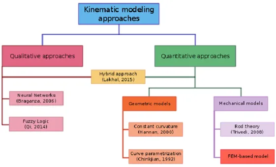
(45) Thèse de Thor Morales Bieze, Lille 1, 2017. 2.4. Work contextualization and contributions. 2.4. 29. Work contextualization and contributions. Given the classification of the approaches towards the modeling and control of continuum manipulators presented in section 2.3.2, it is now possible to position the methodology presented in this work, in the context of the current literature. Fig. 2.13 provides a helpful visualization of the position of our method with respect of other previously proposed methods and their classification.. Figure 2.13: The context of the proposed method in the current state of the art As it is illustrated in the figure, the proposed method is based on the mechanics of the materials, which means that no geometrical assumptions are done in order for the method to be applicable. Moreover, being a mechanicsbased approach, the description provided by the method explicitly accounts for the internal and external loading of the continuum backbone, which means that the deformation caused by gravity or the load of a payload will be reflected in the model. Nevertheless, there are a few important differences between the method here discussed and other mechanic-based methods: First, while most methods are based on Cosserat rod and other elasticity theories, the proposed approach is based on Finite Element Analysis which provides geometrically accurate descriptions of the backbone. Second, the modeling. © 2017 Tous droits réservés.. lilliad.univ-lille.fr.
(46) Thèse de Thor Morales Bieze, Lille 1, 2017. 30. Chapter 2. State of the Art. of actuators, sensors and end-effector is done implicitly by the formulation of the constraints, so no further modeling is required. In the following, the contributions to the field derived from the development of this Ph.D. work are enlisted: • FEM-based quasi-static modeling approach that accounts for complex structural shapes of single and multi-backbones. • The model implementation of two types of actuation systems (i.e. tendons and pneumatic muscles) currently implemented in the majority of designs of soft manipulators. • The integration of sensors in the model that allows for a description of the manipulator in the configuration space. • A closed-loop control strategy for continuum manipulators based on the state estimation of the robot. In the next chapter, the assumptions considered during modeling and the study framework of this methodology (namely Continuum Mechanics and Finite Element Method) are introduced.. © 2017 Tous droits réservés.. lilliad.univ-lille.fr.
(47) Thèse de Thor Morales Bieze, Lille 1, 2017. Chapter 3. FEM-based model of Continuum Manipulators. Contents 3.1. Introduction. . . . . . . . . . . . . . . . . . . . . .. 32. 3.2. Continuum mechanics framework . . . . . . . . .. 33. 3.2.1. Constitutive material law . . . . . . . . . . . . .. 34. 3.2.2. Forces in the continuum manipulator . . . . . . .. 35. 3.3. Finite Element Method . . . . . . . . . . . . . . .. 36. 3.4. FEM-based kinematics of soft manipulators. . .. 38. 3.5. 3.6. 3.4.1. Constraint for the end-effector. . . . . . . . . . .. 39. 3.4.2. Actuator constraint model . . . . . . . . . . . . .. 41. 3.4.3. Sensor constraint model . . . . . . . . . . . . . .. 44. Reduced model in the constraint space . . . . .. 45. 3.5.1. Reduced compliance on the constraint space . . .. 45. 3.5.2. Coupled Kinematic Equations . . . . . . . . . . .. 47. 3.5.3. Inverse kinematic model solution by convex optimization . . . . . . . . . . . . . . . . . . . . . . .. 48. Method implementation . . . . . . . . . . . . . .. 49. 3.6.1. Simulation framework . . . . . . . . . . . . . . .. 50. 3.6.2. Corotational FEM . . . . . . . . . . . . . . . . .. 50. 3.6.3. Mesh generation . . . . . . . . . . . . . . . . . .. 51. 3.6.4. Description of the Compact Bionic Handling Assistant . . . . . . . . . . . . . . . . . . . . . . . .. 51. Simulation of the CBHA . . . . . . . . . . . . . .. 53. Kinematic models . . . . . . . . . . . . . . . . . .. 55. 3.6.5 3.7. 3.8. © 2017 Tous droits réservés.. 3.7.1. Forward kinematic models . . . . . . . . . . . . .. 56. 3.7.2. Inverse kinematic model . . . . . . . . . . . . . .. 62. Conclusion of the chapter. . . . . . . . . . . . . .. 63. lilliad.univ-lille.fr.
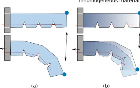
(48) Thèse de Thor Morales Bieze, Lille 1, 2017. 32. Chapter 3. FEM-based model of Continuum Manipulators. 3.1. Introduction. In contrast with rigid robots, soft manipulator kinematics not only depend on the geometry of the robot, but also on the mechanical properties of its material, in particular the stiffness, that dictates the net configuration of the robot under a set of external forces. This statement represents the core of the modeling principle considered in this manuscript. As an example, consider the manipulator in Fig. 3.1 (a). A tendon routed through the structure is pulled to achieve a desired endeffector position. In Fig. 3.1 (b), a manipulator with the same geometry but with inhomogeneous material is actuated in the same manner by the same amount, however, the resulting configuration differs from (a). This is because of the influence of the material stiffness in the kinematics of the manipulator. Inhomogeneous material. (a). (b). Figure 3.1: In this example a tendon is pulled to create the motion of an elastic soft robot. Starting with the same geometry, the material stiffness has an influence on the kinematics (output vs input displacements). While rigid manipulator kinematics can be used to solve positioning problems with the assumption of resistance/counter-actuation to gravity or load effects, soft manipulators easily comply to these forces and deform. To answer the same problems of positioning, it is then necessary to take into account the current deformation (i.e. change of geometry) induced by these forces to obtain a kinematic relation between the po-. © 2017 Tous droits réservés.. lilliad.univ-lille.fr.
(49) Thèse de Thor Morales Bieze, Lille 1, 2017. 3.2. Continuum mechanics framework. 33. sition of the end-effector and the position of the actuators. Another difference between soft continuum manipulators and rigid ones is the impact that external forces (particularly gravity) have on the final pose of the manipulator [Trivedi 2008b]. As mentioned before, in a continuum manipulator, there can be only a finite number of actuated degrees of freedom1 . The state of the remainder of the (infinite) degrees of freedom in a continuum robot backbone will be determined by both the constraints of the controlled degrees of freedom and internal and external forces [Walker 2013a]. In this work, this problem is addressed by a discretization of the degrees of freedom of the continuum manipulator, through numerical methods provided by Computational Mechanics. In the following, the Continuum Mechanics framework is briefly introduced to help us describe the motion of the continuum manipulator based on its deformation and to help the reader to understand the assumptions made in this modeling methodology. This work also explains the methodology of kinematics estimation on a continuum manipulator based on FEM.. 3.2. Continuum mechanics framework. From a Continuum Mechanics perspective, we will consider the structure of a continuum manipulator at a macroscopic level, that is, there is no space between the particles that compose the manipulator, the body of the manipulator fills the entire space it occupies. In this section, we present the basic notions of Continuum Mechanics with the example of a continuum manipulator. The interested reader may refer to the Appendix A.1 for a more formal introduction. Consider the manipulator in Fig. 3.2. with all its material particles occupying a 3-dimensional domain with a starting configuration k0 . Given a set of external loads, the manipulator will deform, changing its geometry. The new deformed configuration of the manipulator is called k i . A material particle of the manipulator will have a position P in k 0 and ¯ in ki . Then, we can always find a function M that maps a position P ¯ from P. P 1. © 2017 Tous droits réservés.. This statement can be extended to any physically realizable system.. lilliad.univ-lille.fr.
Figure

![Figure 2.4: The KSI hybrid actuated manipulator [Immega 1995]](https://thumb-eu.123doks.com/thumbv2/123doknet/3682426.109122/28.892.261.613.220.620/figure-the-ksi-hybrid-actuated-manipulator-immega.webp)
![Figure 2.8: A concentric tube robot or Active Cannula com- com-posed by 3 pre-curved tubes, from [Wu 2017]](https://thumb-eu.123doks.com/thumbv2/123doknet/3682426.109122/31.892.220.695.593.956/figure-concentric-robot-active-cannula-posed-curved-tubes.webp)
![Figure 2.9: The Air-Octor hybrid manipulator composed by a pneumatic backbone which is bent by tendons, as presented in [Jones 2004b]](https://thumb-eu.123doks.com/thumbv2/123doknet/3682426.109122/33.892.281.638.162.535/figure-octor-manipulator-composed-pneumatic-backbone-tendons-presented.webp)
+7


Documents relatifs