Standardisation of chamber technique for CO
2, N
2O and CH
4fluxes measurements
from terrestrial ecosystems
Marian Pavelka1*, Manuel Acosta1, Ralf Kiese2, Núria Altimir3,4, Christian Brümmer5, Patrick Crill 6, Eva Darenova1, Roland Fuß5, Bert Gielen7, Alexander Graf 8, Leif Klemedtsson9, Annalea Lohila10, Bernhard Longdoz11, Anders Lindroth12, Mats Nilsson13, Sara Maraňón Jiménez14, Lutz Merbold 15,16, Leonardo Montagnani17,18, Matthias Peichl19, Mari Pihlatie4,20, Jukka Pumpanen21, Penelope Serrano Ortiz22,23,
Hanna Silvennoinen24, Ute Skiba25, Patrik Vestin12, Per Weslien9, Dalibor Janous1, and Werner Kutsch26
1Department of Matters and Energy Fluxes, Global Change Research Institute, Czech Academy of Sciences, Bělidla 986/4a, 603 00, Brno, The Czech Republic
2Institute of Meteorology and Climate Research – Atmospheric Environmental Research, Karlsruhe Institute of Technology, Kreuzeckbahnstraße 19, 82467, Garmisch-Partenkirchen, Germany
3ECOFUN-Forest Science Center of Catalonia, Carretera de St. Llorenç de Morunys km 2, 25280, Solsona, Spain 4Department of Physics, Division of Atmospheric Sciences, P.O. Box 64, University of Helsinki, Helsinki, Finland 5Thünen Institute of Climate-Smart Agriculture, Bundesallee 50, 38116, Braunschweig, Germany
6Department of Geological Sciences, Stockholm University, Svante Arrhenius väg 8, 106 91, Stockholm, Sweden 7Research Group of Plant and Vegetation Ecology, Department of Biology, University of Antwerp, Universiteitsplein 1, 2610, Wilrijk, Belgium
8Institute of Bio- and Geosciences Agrosphere (IBG-3), Forschungszentrum Jülich, Wilhelm-Johnen-Straße, 52428, Jülich, Germany 9Department of Earth Sciences, University of Gothenburg, Guldhedsgatan 5a, 40530 Göteborg, Sweden
10Finnish Meteorological Institute, P.O. Box 503, 00101, Helsinki, Finland
11Gembloux Agro-Bio Tech, University of Liege, Passage des Déportés 2, 5030 Gembloux, Belgium
12Department of Physical Geography and Ecosystem Science, Lund University, Sölvegatan 12, 22362, Lund, Sweden 13Department of Forest Ecology and Management, Swedish University of Agricultural Sciences, Skogsmarksgränd, 90183 Umeå, Sweden
14Department of Applied Physics, University of Granada, Av. Fuentenueva S/N, 18071, Granada, Spain
15Mazingira Centre, International Livestock Research Institute (ILRI), Old Naivasha Road, 00100, Nairobi, Kenya 16Grassland Sciences Group, Department of Environmental Systems Science (D-USYS), ETH Zurich, Universitaetsstr. 2, 8092, Zurich, Switzerland
17Faculty of Science and Technology, Free University of Bolzano, Piazza Universita’ 1, 39100, Bolzano, Italy 18Forest Services, Autonomous Province of Bolzano, Via Brennero 6, 39100, Bolzano, Italy
19Department of Forest Ecology and Management, Swedish University of Agricultural Sciences, 90183, Umeå, Sweden 20Department of Forest Sciences, P.O. Box 27, University of Helsinki, Helsinki, Finland
21Department of Environmental and Biological Sciences, University of Eastern Finland, Yliopistonranta 1 C, 70211, Kuopio, Finland
22Departament of Ecology, University of Granada, 18071, Granada, Spain
23Andalusian Institute for Earth System Research (CEAMA-IISTA), Universidad de Granada, 18006, Granada, Spain 24Soil Quality and Climate Change, Division for Environment and Natural Resources, Norwegian Institute of Bioeconomy Research (NIBIO), Hogskoleveien 7, 1430, Aas, Norway
25Centre for Ecology and Hydrology, Penicuik EH26 0QB, Bush Estate, Edinburg, United Kingdom 26ICOS ERIC Head Office, Erik Palménin aukio 1, 00560 Helsinki, Finland
Received January 3, 2018; accepted June 26, 2018
A b s t r a c t. Chamber measurements of trace gas fluxes bet- ween the land surface and the atmosphere have been conducted for almost a century. Different chamber techniques, including static and dynamic, have been used with varying degrees of success in estimating greenhouse gases (CO2, CH4, N2O) fluxes. However, all of these have certain disadvantages which have either prevent-ed them from providing an adequate estimate of greenhouse gas exchange or restricted them to be used under limited conditions. Generally, chamber methods are relatively low in cost and simple to operate. In combination with the appropriate sample alloca-tions, chamber methods are adaptable for a wide variety of studies from local to global spatial scales, and they are particularly well suited for in situ and laboratory-based studies. Consequently, chamber measurements will play an important role in the portfolio of the Pan-European long-term research infrastructure Integrated Carbon Observation System. The respective working group of the Integrated Carbon Observation System Ecosystem Monitoring Station Assembly has decided to ascertain standards and qual-ity checks for automated and manual chamber systems instead of defining one or several standard systems provided by commer-cial manufacturers in order to define minimum requirements for chamber measurements. The defined requirements and recom-mendations related to chamber measurements are described here. K e y w o r d s: ICOS, protocol, greenhouse gas, ecosystem, automated chamber system, manual chamber system
INTRODUCTION
Chamber measurements of trace gas fluxes between the land surface and the atmosphere have been conducted for almost a century (Lundegårdh, 1927, 1928). Henrik Lundegårdh is commonly named as the first scientist who measured soil respiration in the field. He already used a chamber placed on a collar that had been inserted into the soil beforehand. For decades, until the eddy covariance (EC) technique has become the standard technique to estimate net carbon dioxide (CO2) exchange (Aubinet et al., 2012),
chamber measurements have been the prevailing technique to monitor the CO2 exchange between the atmosphere and
soil, plant organs or complete ecosystems (Livingston and Hutchinson, 1995; Pumpanen et al., 2004; Wohlfahrt et al., 2005; Acosta et al., 2013). In the case of methane (CH4)
and nitrous oxide (N2O), for which fast and precise
analys-ers have only been developed very recently and are more expensive than fast CO2 sensors, chambers still provide the
majority of information and are the most commonly used flux measurement method (Denmead, 2008).
CO2, CH4 and N2O are the three greenhouse gases
(GHGs) which are most commonly monitored using the chamber method. CO2 is one of the most common and
important trace gases in the earth-ocean-atmosphere sys-tem. It has both natural and anthropogenic sources. Within the natural carbon cycle, CO2 plays a key role in a number
of biological processes (photosynthesis, respiration etc.). Coal, oil, natural gas, and wood mostly consist of carbon, so combustion of these fuels releases CO2 into the
atmos-phere, and this together with land use change processes, has been the cause of the continuous increase in atmosphe-
ric CO2 abundance over the last several decades. Carbon
dioxide abundances are reported in dry-air mole fraction, μmol mol-1, (parts-per-million, 10-6, usually abbreviated
ppm). CO2 concentrations in the atmosphere increased by
40 % from 278 ppm in 1 750 to 406 ppm in 2017, (NOAA/ ESRL, 2017).
CH4 is acting as a strong greenhouse gas, and it plays
important roles in determining the oxidizing capacity of the troposphere and in stratospheric ozone depletion. It has both natural and anthropogenic sources. There are still many regions with strong CH4 sources that are poorly
characterized, including populated regions of the mid lati-tudes of the northern hemisphere, agricultural regions in South and Southeast Asia and the tropics in general, and vast regions of the Russian Arctic, where natural wetlands and fossil fuel exploitation result in significant emissions. Methane abundances are reported as CH4 in dry-air mole
fraction, (parts-per-billion, 10-9, usually abbreviated ppb).
During the same time interval as CO2, CH4 increased by
150 % from 722 ppb in 1750 to 1859 ppb in 2017, (NOAA/ ESRL, 2017)
N2O has both natural and anthropogenic sources.
Sources include soils under natural vegetation, agriculture, oceans, fossil fuel combustion and biomass and biofuel burning. Nitrous oxide is inert in the troposphere. Its major sink is through photochemical transformations in the strato-sphere that decreases the abundance of stratospheric ozone. The units of N2O measurements are dry-air mole fraction
(ppb). N2O increased by 20% from 271 ppb in 1750 to 329
ppb in 2017, (NOAA/ESRL, 2017).
The concentration of the three greenhouse gases CO2,
CH4 and N2O have increased in the atmosphere since
pre-industrial times due to anthropogenic emissions from the use of fossil fuel as a source of energy and from land use and land use change, in particular agriculture. The observed changes in the atmospheric concentration of CO2, CH4 and
N2O result from the dynamic balance between
anthropo-genic emissions, and the perturbation of natural processes that lead to a partial removal of these gases from the atmos-phere (IPCC, 2013).
Chamber measurements are relatively simple to opera- te and adaptable to a wide variety of studies, and they are important tools in situations where the EC technique can-not be applied. Furthermore, they are useful to determine the spatial heterogeneity of fluxes of GHGs, to partition the net fluxes of CO2 into their components (respiration and
gross primary production), as well as to offer supporting data for the gap-filling of the EC data. Even though the ma- nual chamber measurements allow users to investigate the inter-annual variations of soil GHGs and the influence of environmental factors on them during the growing season, they may not be consistent throughout the year and may miss specific weather events; such as wet or dry conditions. Automated chambers have the great advantage of being able to measure continuously for long periods, regardless of
the weather and time of day. The use of automated systems for GHG efflux allows accurate measurements, minimal disturbance of the soil surface, and high resolution datasets for extended periods of time (e.g. Korkiakoski et al., 2017). Due to their advantages, chamber measurements will play an important role in the portfolio of the Pan-European long-term research infrastructure ICOS. However, a universal chamber system (commercial or homemade) does not exist. The respective working group of the ICOS Ecosystem Monitoring Station Assembly (MSA) has decided to ascer-tain standards and quality checks for automated and manual chamber systems instead of defining one or several standard systems provided by commercial manufacturers in order to define minimum requirements for chamber measurements. This manuscript summarizes the main issues presented in the ICOS protocol and instruction documents describing the requirements and recommendations related to chamber measurements.
METHODOLOGY
A) Automated chamber measurements
Measurements methods and instrumentation
In principle, several technical solutions are available to design an automated chamber system for fluxes of CO2,
CH4 and N2O between soil/ecosystem and the atmosphere.
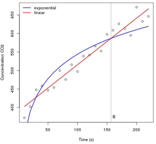
They are typically classified into open dynamic chamber (steady-state through-flow) and closed dynamic chamber (non-steady-state through-flow) systems. In open dynamic chambers, the sample air is withdrawn from the chamber to a gas analyser and replacement air with known gas con-centration is directed to the chamber to maintain pressure equilibrium. During the chamber closure, the chamber headspace reaches steady-state concentration from which the flux can be calculated. The closed dynamic chamber operates in a fully enclosed mode in which the sample air is continuously drawn from the chamber headspace to a gas analyser and returned back to the chamber, and measures the continuous changes in GHG concentration in the cham-ber headspace over a short time. The flux is calculated from this change using either a linear or non-linear fit model. For detailed description of the chamber types, see Livingston and Hutchinson (1995) and Pumpanen et al. (2009).
Since most of the chamber systems (commercial as well as home-made) used for GHG flux measurements are based on the closed dynamic approach, the recommended stand-ard method for ICOS is a closed dynamic chamber system. Two different ways to design air sampling in closed sys-tems are: (1) the system integrates all required gas analysers in the field, (2) automatic in-situ collection of air samples which are afterwards analysed in the laboratory. Given the fact that this protocol aims to suggest the optimum infra-structure for a period of at least 20 years, we recommend an automated chamber system comprising GHG analysers that can be setup in the field to avoid labour-intensive analyses
in the laboratory and to minimize the running cost. On the other hand, manual measurements are still encouraged to estimate the spatial heterogeneity.
Each measurement technique, design and setup reveals various advantages and disadvantages in comparison to other approaches. The method has construction issues that have to be taken into account regarding the ecosystem to be monitored. The aim of the given specifications is to ensure minimization of potential problems and shortcomings asso-ciated with chamber-based flux measurements conducted at ICOS ecosystem stations. A typical chamber system for GHG measurements will consists of the chamber itself, a collar inserted into the ground onto which the chamber is secured, a sampling unit transferring the chamber head-space air sample to a gas analyser, and a controlling unit to operate the chamber system and store the measurement data.
Chamber design
It is almost impossible to define a standard chamber, because different ecosystems require different chamber designs. For example, a small chamber designed for forests with stony soil and small understory vegetation is not suita-ble for grasslands and croplands with tall plants. Therefore, specific ecosystems require customized solutions.
The chamber design and measurement protocol should aim to minimize the disadvantages of the chamber systems,
e.g., changes of the microclimate inside the chamber, such
as radiation, precipitation, temperature, wind speed, and litter input. Special attention must be paid to pressure equi-librium between the chamber headspace and the ambient air, in particular, during the closing of the chamber but also during the entire measurement period when air samples are taken from the chamber headspace to avoid bias on cham-ber air concentration developments over time.
Chamber design requirements and recommendations The chamber design depends on the purpose of the mea- surements. The design has to fulfil the following require-ments and recommendations:
1) Opaque chambers have the advantage that during the short closure period of < 5 min the headspace air tempera-ture does not increase as much as in a transparent chamber, and thereby minimises unintended warming effects on soil components/plants. If transparent chambers are used, the whole chamber (wall and lid) should be painted or covered with tin foil in order to block out sunlight. We recommend to paint it with a white matt colour to avoid possible direct reflection of the sun on nearby radiation sensors. Apart from opaque chambers, measurements with transparent cham-bers are recommended (but not obligatory) to facilitate the quantification of the contribution of ground vegetation to the net ecosystem exchange (NEE) at sites where the con-tribution of ground vegetation is relevant (concon-tribution of ground vegetation to NEE >10%).
2) Chamber shapes are commonly cylindrical or rec-tangular in cross-section, although any chamber shape is acceptable. A cylindrical shape allows better mixing of the enclosed air, while a rectangular shape generates dead space in the top corners of the chamber where enclosed air may not be mixed properly (Livingston and Hutchinson, 1995).
3) The chambers should be fabricated of non-perme-able and inert materials, i.e. Polyvinylchloride (PVC), Polypropylene (PP), Polyethylene (PE), Acrylonitrile-Butadiesen-Styrene (ABS), Polytetrafluoroethylene (PTFE- Teflon), Polymethyl Methacrylate (PMMA), stainless steel or aluminium. The outer colour of chambers should be white.
4) Chambers must be fitted with a vent in order to avoid pressure changes when closing and opening the chambers (Christiansen et al., 2011), but also during the measure-ments period. The inner diameter of the vent is a function of chamber volume (Hutchinson and Mosier, 1981). Another possible solution is a vent-tube (Xu et al., 2006) in order to achieve the chamber pressure equilibrium, mainly at windy sites.
5) Adequate air mixing must be assured inside the chamber headspace. This can be achieved by the airflow between the chamber and the GHG analyser (the majority of commercial systems) or by installing fan/fans inside of the chamber to achieve air movement similar to the out-side averaged wind speed close to ground surface. The optimum seems to be a system where chamber ventilation follows the average wind speed a few minutes before start-ing the measurements. In case of constant fan speed the ventilation should be gentle and not too strong, an exces-sive air movement inside the chamber is thought to disrupt the high laminar boundary layer above the soil (Le Dantec
et al., 1999; Koskinen et al., 2014). The average speed
of air movement inside the chamber should be less than 0.5 m s-1; measured at four points across the chamber and at
half the height of the chamber. The main airstream should not be directed towards the soil to prevent unwanted sup-pression of gas diffusion from the soil into the chamber atmosphere, or to avoid flushing of soil air to the head-space. Visualization of the movement of the air inside of the chamber can be done using a small source of smoke (e.g. cigarette).
Another possibility is to control the fan speed follow-ing outside wind conditions usfollow-ing a sensitive ultrasonic anemometer installed close to the ground to have similar conditions inside and outside the chamber. In this case, fan speed should not be changed during one measurement of one chamber – an average speed calculated from previous about 2 min wind speed is recommended.
6) The Venturi effect is the reduction in fluid pressure that results when a fluid flows through a constricted section of a pipe (Bahn et al., 2009; Bain et al., 2005; Davidson
et al., 2002; Kutsch et al., 2009). It should be investigated
for each chamber design following the protocol of Bain et
al. (2005), when the chamber ventilation is switched on.
Interactions between the Venturi effects and internal venti-lation are complex and not fully clarified. Since turbulence can cause pressure fluctuations over bare soil (without any chamber deployed), which can enhance gas transport, the chamber design can modify these fluctuations in both direc-tions. The optimum seems to be a system where chamber ventilation follows the average wind speed a few minutes before starting the measurements.
7) Collar insertion should assure a good chamber-to-soil seal, however, at the same time it is necessary to minimize the cut of the surface rooting zone in order to avoid trench-ing effect (see section soil collars).
8) Effects of chamber design on rain and fertilizer addition/spreading inside the measured area have to be minimized as much as possible using proper design and measurement time schedule (see Chamber and system design testing).
9) To prevent damage or cutting of vegetation inside the collar during the closing of the chamber (e.g. grasslands and croplands), a thin metal wire mesh disposed along the inner circumference of the collar is recommended.
10) If is planned to close the chambers for long time (> 30 min) due to N2O/CH4 measurement, it is
recommend-ed to take into account that the insertion collar depth is generally a function of closure time (De Klein and Harvey, 2012). Therefore, it is necessary to increase the collar inser-tion depth during its installainser-tion.
11) Inlet tubes (pipes) should not be located less than ½ of the chamber height and should be fitted with a net or filter to avoid insects incoming to the measurement sys-tem. If tubing is longer than aprox. 10 m, its permeability to measured gases must be tested again. To avoid damage, the chamber system should be in a fenced area in areas frequented by large animals (cattle, sheep, wild boar, deer, bear etc.).
Auxiliary measurements
Each chamber should be instrumented with sensors for measuring the following variables, whose logging interval should be coordinated with the sampling of the analysers between 0.1 and 1 Hz:
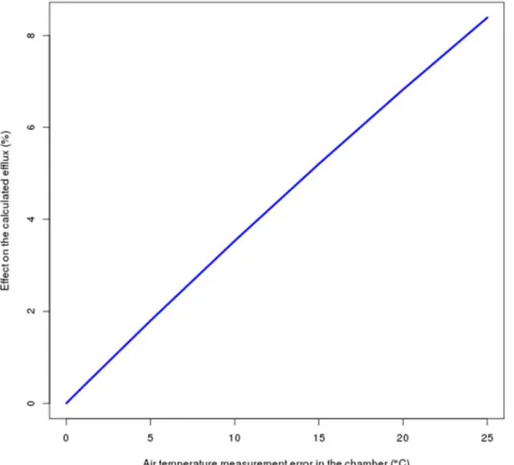
• Air temperature: The position of air temperature sen-sor should not be too close to the wall or lid to prevent biased values due to surface heating of chamber material. Its main purpose is the measurement of temperature fluctu-ations during closure time. The sensor should be protected from direct sun light. These data are necessary in the pro-cess of flux calculations.
• Soil temperature: Soil temperature should be meas-ured inside each collar; the depth of these measurements depends on the type of ecosystem and soil. For CO2 we
recommend estimating the proper depth in order to syn-chronize daily courses of soil temperature and soil CO2
efflux (Graf et al., 2008; Pavelka et al., 2007; Subke and Bahn, 2010). However, following the compulsory measure-ment depths of soil temperature in the upper soil layer, one measurement at 5 cm is mandatory and one measurement as close to the soil surface as possible is optional.
• Soil moisture: A soil water content sensor should be installed close to each collar when a small chamber is used or inside of big chambers. The measurement depth should be close to the soil surface (5 cm) for CO2 and following the
sensor manufacturer recommendations. In special cases,
e.g. water saturated soils.
If transparent chamber measurements are used it is re- commended to measure photosynthetically active radiation (PAR) and relative humidity inside each chamber. We also recommend monitoring the transparency of the chamber and temperature increase during these measurements.
Soil collars
Collars are required to provide an airtight seal between the chamber and the soil surface, and to ensure sufficient stability to the chamber. Soil collars or frames for auto-mated chamber measurements should consist of inert, non-permeable and non-reactive materials i.e. PVC, PP, PE, ABS, PTFE-Teflon, PMMA, or stainless steel. Design and size of the collars should minimize disturbances to the root system and shelter effects for rainfall, litter fall or fertilization. Since the optimal collar design depends on the ecosystem type, more specifications are given in the respective sections (Specifications for ecosystem types). To minimize disturbances of the soil and the roots it is pivo- tal to insert collars as shallow as possible into the soil. The depth of insertion should account for the porosity of the topsoil, as higher porosity requires deeper insertion. In ecosystems with no permanent rooting of plants (e.g. agri-culture, grasslands), the minimum insertion depth should be 0.03 m and the maximum should be 0.15 m depending on ecosystem type and rooting depth to minimize root distur-bance or cutting. In ecosystems with permanent rooting of plants (e.g. forest ecosystems), the collars should be placed on top of the humus layer and only pressed firm but gently into the humus to avoid cutting the roots. Then the collars should be anchored steadily into the mineral soil using spe-cial anchoring screws that can be adjusted depending on the root development. After the installation of the soil collars measurements of GHG can be started. Acquired data has to be analysed for effects of collar insertion (disturbance) in measured fluxes on the base of principal investigator (PI) experience.
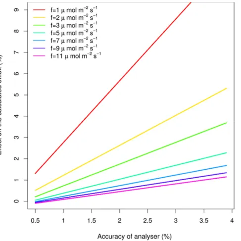
Requirements for GHG analysers
The use of a specific instrument, such as the analyser type or model, is not imposed. However, in order to ensure high quality standard of the chamber measurements, a cer-tain scale of range, precision and accuracy of the instrument will be specified. One of the most important parameters of
the analyser is the short-term stability, which is the drift in baseline concentrations over a timescale of few minutes. The measurement range has to cover all concentrations of monitored GHGs that can appear during the time of meas-urement. Most of the infrared gas analysers measure also water vapour content. In other words, GHG concentra-tions in moist air are recorded instead of dry air, due to the absence of an automatic application of the water vapour dilution correction. Brümmer et al. (2017) have shown that automated measurements with a high precision quantum cascade absorption laser spectrometer (QCLAS) for N2O
in the field requires only a few minutes of chamber closure, even when fluxes are lower. On the other hand, Korkiakoski
et al. (2017) demonstrated that very small CH4 fluxes,
vary-ing from uptake to emissions, can be detected with high precision analysers over a short closure time. Therefore, we recommend a minimum closure time of 5 min, to ensure that even very low fluxes can be measured accurately. Using a system that is able to measure the mixing ratios of N2O, CH4 and CO2 in the field should enable continuous
measurements for each chamber at least every two hours. The required parameters for each analyser are:
• Measurement range depends on the time of chamber clo-sure and its volume/surface ratio:
o CO2: at least 100 – 2000 ppm
o CH4: at least 0 –10 ppm
o N2O: at least 0 – 2 ppm
o H2O: at least 0-60 ppt (for water vapour dilution cor-
rection);
• Minimal output sampling frequency 0.1 Hz for CO2
• Minimal output sampling frequency 0.1 Hz for CH4
• Minimal output sampling frequency 0.1 Hz for N2O
• Accuracy of the CO2 analyser should be ≤ 2% of the
reading.
• Low root mean square (RMS noise with 1 s signal filtering ≤ 1.5 ppm CO2, at ambient concentration).
• Accuracy of the CH4 and N2O analyser should be
mini-mum 1 ppb in 100 s.
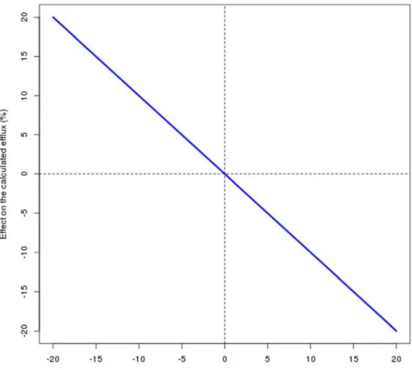
• Another crucial parameter is the stability of the analyser. If any measured gas is injected with constant concentration to the analyser, the output value from the analyser must be stable, changes during 5 min measurements should not be more than 1.5 ppm for CO2 (Appendix: Fig. 1A), 0.5 ppb
for CH4 and 0.1 ppb for N2O.
Chamber and system design testing
The following tests should be done for home-made automated chamber systems.
Leakage testing
Each chamber and measurement system must be tested for air-tightness. The testing measurement can be done in the field or in the laboratory conditions provided that concentration of the gas used to test leakages is close to ambient conditions (ca. 400 ppm for CO2). For chamber
air-tightness testing a special frame that is air-tight at the bottom of the chamber (e.g. mounted on a metal or plastic sheet from which the chamber was made) has to be con-structed. Then the chamber is placed onto the frame in the same way as during field operations. A known CO2
concen-tration is injected in the chamber to achieve a concenconcen-tration similar to that at the end of a field measurement (or higher) (typically the target concentration could be ambient con-centration plus approx. 400 ppm, depending on the type of ecosystem). Then the CO2 concentration inside the
cham-ber is monitored in 10 s intervals for 5 min, which is the standard measurement time (typically from 2 to 5 min, in the case of CO2 chamber measurement systems; may be
more for CH4 and N2O measurement systems). The varia-
tion caused by possible leakage should be ≤ 3% of the measured flux. This test should be done separately for all the gases measured, CO2, CH4 and N2O.
Impact of pressure changes during chamber closure Even a small pressure difference between chamber head- space and the atmosphere, as low as 1 Pa, has been shown to cause significant errors to the measured CO2 efflux
(Fang and Moncrieff, 1996; Longdoz et al., 2000; Kutsch
et al., 2001). This testing can be realized during the above
described leakage testing using the sealed bottom frame. The pressure difference between the chamber headspace and the atmosphere should be monitored continuously dur-ing the whole chamber operation, includdur-ing the closdur-ing of the chamber. Overpressure during the closing of the cham-ber has to be smaller than 10 Pa, and less than 0.1 Pa during the measurement. In the case of overpressure during the chamber closing, an extra pressure equilibrium active vent is recommended in order to prevent pressure alteration
dur-ing chamber closdur-ing. Therefore, a hole of about 5 cm in diameter should be made on the top of the chamber. The hole should be closed automatically by a lid few seconds after the chamber closing. The pressure effects caused by chamber closure have to be monitored using a differen-tial pressure transducer during testing phase of the system and documented, and checked in order to facilitate reliable chamber measurements.
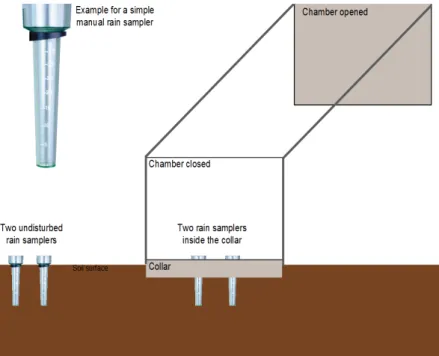
Testing of rain intensity altered by the chamber
Effects of the chamber design on rain inside the mea- sured area have to be checked and documented under field condition in an open area, and not underneath a forest canopy, before the installation of the system. A series of rainfall events should be studied by means of at least two simple manual rain samplers of which one will be placed inside the chamber and the other far enough away from the chamber system so they can be considered as independent and not influenced by the chamber (Fig. 1). All samplers will be read out and emptied regularly. The test should be conducted with a minimum of 2 chambers, 3 rainfall events and collecting at least 20 mm cumulative rainfall.
The following measurements have to be conducted: 1. the chambers are permanently open (influence of the rack and the lifted chamber);
2. the chambers will be closed for 3 – 10 min every hour (following typical measurement schedule in the field).
If a deviation from the undisturbed rainfall by more than 20% occurs, the chamber design will not be accepted for long-term measurements within ICOS.
Testing the shading from solar radiation
The effect of solar radiation shading of an open cham-ber has to be tested under field conditions in an open area (without canopy). A PAR sensor should be placed in the middle part of the collar, and a second PAR sensor outside of the collar, far enough away from the chamber system that they can be considered as independent and not influenced by the chamber; following the design depicted in Fig. 1 for rain samplers. The measurement should be carried out for a minimum of two full days and include a cloudy day and a sunny day. If the difference in the PAR daily sums between the two sensors is more than 20%, the chamber design will not be accepted for long-term measurements within ICOS. However, the chamber should be oriented to minimise possible shading of the chamber construction and compo-nents to the measured area, when the chamber is opened. Testing the effect of ventilation on air mixing
The test should be done under field conditions, in the absence of rain and high temperature, avoiding large tem-perature fluctuation and preferable during overcast periods. The fan should be switched on for at least 24 h in all cham-bers and then switched off for approximately 24 h in one half of the total number of chambers (three chambers in case that the total number is five chambers). Thereafter, the fan must be switched on again in all chambers and concen-tration measurements should continue for at least 24 h.
Chamber system calibration and maintenance
The GHG analyser of the chamber system must be calibrated or validated according to the manufacturer re- commendations and at least once per year. The chamber system should be controlled regarding chamber operations and quick leakage testing (by breathing to critical parts of the system, sealing of the chamber closing) once per month in order to avoid any malfunction of the system.
Spatial and temporal sampling design Spatial sampling strategy
Automated chamber system allows studying the dynamics of GHG exchange at a high temporal resolution for extended periods of time but due to a limited number of automatic chambers it is not possible to fully explore the spatial variation at the full EC footprint area. Therefore, five (six in special cases; see Specifications for ecosys-tem types) sampling points/chambers, depending on type and occurrence of vegetation, were chosen as the required minimum number for the automatic chamber systems. This decision is based on a compromise between economic rea-sons and scientific points of view. The automatic chambers should be located within the EC footprint area but not in the main wind direction in order to avoid disturbance to the EC measurement. Also, the chambers should cover the main representative parts of the soil surfaces (see Specifications
for ecosystem types) according to the studied ecosystem. In case of no predominant wind direction, it is possible to install the chambers in four different quadrants around the EC tower to cover the EC footprint.
To quantify the spatial heterogeneity of GHG fluxes a survey with manual chamber campaign is recommend-ed (see Specifications for ecosystem types for the manual measurements in specific ecosystems). These sampling points should be located in the EC footprint area.
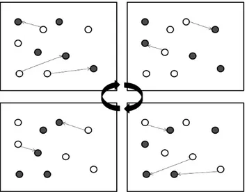
In order to minimize the chamber disturbances to the soil and to better cover the spatial variability, the automated chamber system must comprise of twice as many collars than chambers so that each chamber is manually moved between at least two collars at least once a year. However, not all collars should be moved at the same time as shown in the following example, where five chambers are moved between ten collars in four steps (Fig. 2). Moving only two or three chambers at one step, guarantees continuous data for the other chambers and the possibility to relate the fluxes from different collars to each other. For “relaxing positions”, set of special short collars should be made in order to minimize influence of physical properties as solar radiation, precipitation and litter fall input. The role of the “relaxing collars” is to keep the original measurement position and minimize soil disturbance (roots cutting) after reinstallation of the measuring collar to the original posi-tion. The height of the relaxing collar should be equal to the insertion of the measuring collar. It means the upper edge of the relaxing collar should be at the same level as soil surface. In order to facilitate visibility of the relaxing posi-tion it is recommended to mark each posiposi-tion with a small flag with north direction about 20 cm from the collar. Collar
Fig. 2. Example for rotation of 5 permanent chambers on 10
col-lars. Collars without chamber are in white circle and collars with chamber are black circle. The collars without chamber (relaxing collar) should be measured regularly in campaigns. The narrow arrows indicate the change of relaxing collar position while the wide arrows the rotation change during a year.
positions for automated measurements should be changed preferably during reinstallation of the system after winter period, in accordance of measurement and relaxing collars scheme description (see spatial sampling strategy).
Special attention should be paid to the installation of tall chambers designed for measurements in ecosystems with tall plants (e.g. grassland, wetland or cropland). Tall chambers that are lifted upwards can disturb the turbu-lence structure inside the footprint. Notwithstanding, the best arrangement covers those sub-habitat components that have the highest representativeness and are expected to contribute to the bulk of the exchange. The number of used chambers in different habitats should respect the ratio of the habitats area in the footprint (Merbold et al., 2011).
Concerning chamber GHG measurements in winter, measurements should be continued during winter if pos-sible. There exist chamber designs specifically constructed to tackle most of the challenges related to wintertime (Koskinen et al., 2014; Korkiakoski et al., 2017). For example, supporting the collar by separate legs, which allows the vertical lifting of the whole chamber and install-ing extension, collars between the frame and bottom collar prior to snowfall significantly lessen the disturbance to the snowpack. Relevant CH4 and N2O fluxes may occur in
winter, particularly in peatlands (Korkiakoski et al., 2017), but also in other ecosystems with increased mineralization of soil organic matter during the freezing and thawing of soil. If chamber measurements prove to be too challeng-ing, we recommend using other techniques to reasonably identify the spatial and temporal heterogeneity of GHG fluxes during winter. These includ a gradient method within the snow pack (Merbold et al., 2013; Suzuki et al., 2006; Mariko et al., 2000) or the soil (Pumpanen et al., 2008; Pihlatie et al., 2007). Therefore, if it is not possible to con-tinue chamber measurements through the whole winter, we recommend performing chamber measurements as long as the environmental conditions (absence of snow or flood-ing, particularly) allow to do so. Particularly we encourage researchers to cover the transition periods between the sea-sons, e.g. fall to winter including the first snow cover and also potential freeze-thaw events in early winter and spring. This is to account for potential GHG pulses, which may be caused by increased mineralization and/or increase or reduction in water content in the soil.
Temporal sampling strategy
Automated chamber systems allow studying dynamics of GHG fluxes in high resolution for extended periods of time. Therefore, it is expected that the whole vegetation season will be monitored. The minimum time resolution for individual GHG flux measurements should be one mea- surement per hour/per gas per each chamber. Using a sys- tem that is able to measure the mixing ratios of N2O, CH4
and CO2 in the field should enable hourly measurements of
each chamber per day. In case of higher number of cham-bers (more than five) the minimum time resolution for all measured GHG can be prolonged up to 2 h per each cham-ber. As stated in the previous section, in regions where the winter period (e.g. Nordic countries, mountain areas) has extreme environmental conditions (low temperatures, high snow cover, etc.) automated measurements of GHG fluxes are not expected but encouraged during winter months. Companion variables
Beside soil-meteorological variables such as soil tem-perature and moisture, vegetation characteristics inside the collars (including relaxing collars) should be monitored (species identification, cover fraction, LAI, vegetation height, digital photos) twice a year (at the beginning of the growing season and at the maximum of understory vegeta-tion) in order to document the possible long-term impact by the chambers. Moreover, five-control plots, apart from the relaxing ones, should also be monitored. They should be located in representative positions up to five metres from the measuring/relaxing collars.
B) Manual chamber measurements
Although being labour-intensive, manual chamber mea- surements are simple, low cost and therefore conducted by a multitude of researchers worldwide (Appendix: Table A2). Even though regular manual chamber measurements are not mandatory within ICOS they can add valuable information and data on soil GHG exchange:
• in case of limited numbers of automatic chambers (a minimum of 5 chambers was defined) additional manual chamber measurements are recommended to characterize spatial variability of soil GHG exchange in the EC footprint area;
• manual chamber measurements can complement automatic measurements at times when automatic chamber systems cannot be operated (e.g. wintertime, intensive field preparation);
• for all sites without automatic measuring systems regular manual chamber measurements are recommended for estimating annual sink and/ or source strengths of soil GHG exchange.
Therefore, here we aim on reflecting main issues of sampling design, measuring procedure and GHG concen-tration analysis, in order to harmonize manual chamber measurements of soil GHG exchange across ICOS sites.
Measurement methods and instrumentation Chamber design
A standard manual chamber is almost impossible to be defined, because different ecosystems require different chamber designs and different research groups already use different kinds of chambers (Appendix: Table A2).
If applied in combination with an automatic measu-ring system, manual chambers and collars ideally should have the same dimension and should be constructed from the same material as automatic chambers. If this is not fea-sible, manual chamber and collar designs should follow the technical requirements given for automatic chamber systems; most importantly taking into account, the mini-mum chamber size of 0.2 x 0.2 m or an equivalent covered ground area. As outlined for automatic chamber measuring systems chamber/collar systems should be tested against leakages and pressure changes during sampling. In case of manual survey using gas chromatography, the pressure change issue can be easily minimized by a relatively high chamber headspace volume compared to total volume of sample air taken for GHG concentration analysis (factor of at least 25).
In case those manual chamber measurements are con-ducted to complement automatic chamber measurements in wintertime, note that snowy conditions require a diffe-rent measuring setup. The most commonly used method is a snowpack concentration gradient method where the flux is calculated from gas concentration gradients and snow density. Chamber methods have been applied by inserting the chamber on top of the snow or by directly inserting the chamber into the snow (with or without an extension). The snowpack concentration gradient method involves uncer-tainties in gas diffusion and snow density measurements, while the chamber method may give a biased estimate of the flux due to undefined source area in the snow beneath the chamber. Selection of the most suitable method, as well as the reasonable frequency of winter measurements in snowy conditions are site specific and need to be judged by the site PI. We anticipate future research targeting improve-ments in snow flux measureimprove-ments but currently suggest the snow gas concentration gradient method to be preferable used at significant heights of snowpack.
Auxiliary measurements
For calculation of molar volume (term of the flux cal-culation routine) measurements of temperature inside the closed chamber and air pressure at the measurements site are mandatory. Most suitable are mobile temperature sen-sors with internal loggers which can be placed inside any chamber or at least in a subset of three chambers.
Measurements such as soil moisture and soil temperatu-re atemperatu-re temperatu-recommended to be taken with portable probes at any chamber position before sampling in order to allow corre-lation of soil GHG fluxes with environmental parameters. Further measurements such as vegetation dynamics/ charac- teristics (plant composition, height etc.) should be taken regularly and should also be documented by photographs.
Spatial and temporal sampling design
Characterization of soil GHG exchange in the footprint area
Characterization of soil GHG fluxes in the footprint area should be based on a number of at least 25 positions. If root disturbance is an issue, all collars should be perma-nently installed according to the recommendations given in the specifications for ecosystem types in the automatic chamber section. Collar placement should representatively cover any heterogeneity (soil, vegetation, topography etc.) in the EC footprint area. Manual chamber measurements should, wherever applicable, cover seasonal changes (win-ter, spring, summer and autumn) and ecosystem specific events such as re-wetting, freeze-thaw cycles and fertili-zation/harvest events. Due to potential diurnal patterns of soil GHG emissions, it is recommended to do measure-ments every 4 h (e.g. 06:00, 10:00, 14:00, 18:00; 22.00; 02:00) and a minimum of 4 measurements during the day (e.g. 6:00, 10:00; 14:00; 18:00), for more details concern-ing chamber measurements time schedule see Darenova et
al., 2014. Particularly, night-time measurements are very
valuable since a lot of night-time EC data is rejected due to low turbulence.
Note that if an infrared gas analyser is available for automatic chamber measurements, the same sensor can be connected to a single chamber with sufficiently long sampling tubing (approx. 10 m), which can be subse-quently placed at all collars in the footprint area (“fast box” approach: Hensen et al., 2006).
Estimation of sink and/or source strengths of soil GHG exchange
At sites without automatic measuring systems, regular manual chamber measurements are recommended for esti- mating the annual sink and/ or source strengths of soil GHG exchange. Following the minimum requirements of the automatic chamber measurements at least 5 col-lars should be representatively placed in the footprint area. Measurements should be conducted at least weekly, but more often (daily – every other day) during times of expected elevated fluxes. There is evidence from several studies that the most suitable sampling time for GHG emis-sions is 09:00 – 10:00 h when fluxes best represent the daily mean (Darenova et al., 2014). However, since this can vary across ecosystems and seasons, it is recommended to seasonally (winter, spring, summer, autumn, including eco-system specific events) characterize possible diurnal flux patterns by sub-daily measurements in 4-h time intervals (e.g. 06:00, 10:00, 14:00, 18:00; 22.00; 02:00) but at least 4 measurements during the day (e.g. 6:00, 10:00; 14:00; 18:00). This characterization can further guide definition of flexible sampling times best representing mean daily emis-sions, to avoid biased estimation of annual GHG exchange budgets. Generally, the relevancy and frequency of these
measurements is ecosystem and management specific and therefore best to be decided by the site PI. Note that diurnal patterns can be insignificant e.g. in cold (except freeze-thaw) and dry periods.
Sampling procedure
For soil respiration the use of an infrared gas analyser (IRGA) with circulating chamber air via outlet and inlet tubing is recommended. For N2O and CH4 exchange the
chamber air can be sampled with syringes at minimum 4 times over the chamber closure period. In general, cham-ber closure time should be kept as short as possible and should not exceed 45 min. Ideally, measurement of soil CO2 and N2O/CH4 fluxes can be combined, i.e.
short-term IRGA measurements short-terminated at CO2 increase of
20-100 ppm followed by syringe sampling (t0 = 2-5 min, t1 = 15 min, t2 = 30 min, t3 = 45 min). This would require sequentially closing of manual chambers. IRGA inlets and outlets should be easy and quick to connect. The chambers’ sample air outlet should be equipped with stopcocks so that the sampling line can be closed after termination of IRGA measurements and the inlet can be further used for the syringe sampling. Number of chambers to be sampled at the same time (e.g. sets of 5) mainly depends of man power and distance between the chambers. In case of any constraints with the above sampling procedure, separate sampling of CO2 and N2O/ CH4 emissions is recommended.
If analytical capacities are an issue (e.g. in case of investigating spatial variability of soil GHG fluxes in the footprint area), the gas sample pooling technique may be helpful. It proposes to collect composite gas samples from several chambers instead of the conventional practice of analysing samples from chambers individually (Arias-Navarro et al., 2013).
To minimize septum penetration, use of stopcocks (also for syringe sampling) is highly recommended. Syringe samples need to be transferred into gas sample contain-ers (vials) for further analysis by gas chromatography or laser spectroscopy. Vials are recommended to be evacuated (< 100 Pa) and additionally flushed with sampling air at least once the vial´s volume. To avoid dilution with ambient air vials should be over pressurized by at least the sample volume used for gas chromatographic (GC) analysis.
Quality control for GHG concentration analysis with gas chromatography
In general, gas chromatographs are equipped with an Flame Ionization Detector (FID) for CH4 and an Electron
Capture Detector (ECD) for N2O concentration analyses.
In addition, CO2 concentrations can be detected either by
use of a methanizer and FID or by a Thermal Conductivity Detector (TCD). An important issue to be considered in terms of quality control is adequate separation of N2O and
CO2 since they can have similar retention times when using
e.g. porous polymer columns (HayeSep) before the ECD.
Because of non-linearity of ECDs at high N2O
concen-trations (>1000 ppb, ECD dependent, should be checked by the user), a thorough multipoint calibration is recom-mended. In normal operation an adequate (about 20% of analysed samples) number of standards for calibrating the GC system is required e.g. to cope with temporal drifts.
Air sample containers with caps need to be leak-proof, clean and made of material(s) which do not react with N2O
and CH4 (CO2) e.g. glass vials (Exetainer®, Labco Limited,
High Wycombe, UK). The container should remain gas-tight after sample transfer to prevent sample dilution during storage until analysis. Such glass vials have screw-on plastic caps with rubber septa. Experience shows that gas tightness is achieved when the cap is screwed on ‘finger tight’, followed by another quarter-turn. Under pressure in evacuated vials allows quality check of vial tightness while the sample is transferred from the syringe and remain-ing overpressure allows a potential quality check durremain-ing storage. Rochette and Bertrand (2003) report and discuss results of a comparison of polypropylene syringes and glass vials.
For initial quality check of air sample containers and GC performance it is suggested to perform the following test:
Fill 40 air sample containers with calibration standard (e.g. CO2, N2O, CH4, synthetic air mixture), if possible 20
each in two different concentrations (i.e. ambient and high-er/ lower than ambient). Analyse 5 ambient and 5 different from ambient after 1, 2, 3 and 4 weeks of storage. Evaluate results of these samples with analyses of 10 additional vials (with same standards) which are filled directly before being sampled by the gas chromatograph system. The test reveals if there are problems of sample dilution during storage and characterization of temporal stability of the gas chromato-graph system.
After manual chamber measurements are conducted, an additional test with standard gas provided in unknown con-centrations by a central lab is suggested for further quality control of the individual partner sampling procedures.
C) Specifications for ecosystem types
Croplands
Measurements of CO2 effluxes are very useful for
all croplands, while measurements of N2O and CH4 are
restricted to sites where fluxes of these gases are relevant. This should be verified with a measurement campaign during a period when the fluxes are expected to be high. Chamber design should follow the general requirements mentioned above. CO2 should be measured automatically
within the same system as N2O. Crops should be included
for the purpose of direct measurements of ecosystem CO2
due to technical reason, CO2 should be measured
auto-matically on bare soil with no plants inside the chamber to get the soil component of CO2 efflux. This can be done in
a parallel approach with a system of small chambers. Due to the commonly observed low proportion of CH4 on the
total GHG budget of agricultural sites, automated meas-urements of CH4 are not mandatory. To identify a site’s
general exchange characteristics and levels, CH4
measure-ments should be conducted as a part of the manual chamber campaigns (see below). If automated measurements of any GHG will be carried out with plants and on bare soil, the number of chambers should be at least three per variant (three chambers with plants and three chambers on bare soil). In the case of only one variant at least five chambers must be used.
Automated measurements of CO2 and N2O
(plants included in chamber)
• Automated chambers for the measurement of CO2 and
N2O should cover area from 0.03 to 1 m2. If square shaped
chambers are used the minimum size of covered ground area should be 0.2 x 0.2 m.
• The chamber height should be at least be 0.3 m, but should in any case accommodate crop height. Extensions can be attached to the regular chamber during the grow-ing season, but should only be used if necessary to keep chamber dimensions as feasible as possible and to prevent insufficient air mixing inside the chamber.
• Soil collars should be inserted at least 0.09 m into the ground and extend no more than 0.05 m above the surface. Nevertheless, collar insertion should be minimized in order to avoid root disturbance. Ideally, collars will be inserted immediately after sowing of the crop to allow roots to grow without later disturbance.
• A minimum standard of three opaque chambers is re- quired for the combined CO2 and N2O measurements where
plants are included.
• Measurements of investigated GHG and data collec-tion should be started immediately after collar installacollec-tion. Automated measurements of CO2
(plants not included in chamber)
• Automated measurements of soil CO2 efflux should be
conducted with chambers covering a ground area between 0.03 and 1 m2.
• Heterogeneity of root density should be considered by putting chambers in different distances from plant rows (from a few centimetres from the nearest plant to middle part of space between the rows).
• As a minimum standard three opaque chambers are required for soil CO2 efflux measurements on bare soil.
• Measurements of investigated GHG and data collec-tion should be started immediately after collar installacollec-tion.
Manual measurements of CO2, N2O and CH4
• Chambers for manual CO2, N2O and CH4
measure-ments should have the same dimensions as chambers for the automated measurements that include plants if possible.
• Soil collars should be installed at least 24 h before the first measurements (Bahn et al. 2009).
• Manual chamber measurements should be made every 2-3 years on at least 25 different positions and this at least two times a day when maximum and minimum CO2 fluxes
can be expected within the EC footprint.
• It is recommended to undertake these campaigns when significant GHG fluxes are expected and during appropriate conditions for the EC measurements.
General operating instructions for chamber deployment • In case no big chamber system, which covers taller plants, is available, smaller chambers may be used and placed between the rows of plants is possible (e.g., maize, sunflower, etc.). If there is not enough space for a proper installation (e.g., between rape seed plants, wheat, barley,
etc.), single plants should be removed directly after
ger-mination to assure measurements under conditions that are as natural as possible. Disturbance of plots should be minimized.
• Site operators should ensure a so-called ‘conditional random distribution’ of chambers. This means that knowl-edge about site characteristics, particularly soil properties, is required to cover the heterogeneity within a field. For example, if some parts of the land area are dominated by clay soil, others by silt and/or sand, the total number of available chambers should be evenly distributed to the respective soil type class (e.g., 2 to the sand, 2 to the silt, and 1 to the clay-dominated section of the field if 5 cham-bers are available) and randomly distributed within each class.
• Collar positions for automated measurements should be changed once a year, preferably after soil preparation.
• The following information is required: o Date and time of collar installation. o Date and time of measurement start.
o Date of fertilizer application plus fertilizer type and quantity.
o Numbering of collars and chambers. As all sam-pling positions change once a year, all measurement spots, i.e. collars, should be numbered consecutively to ensure a specific ID for each location. Chambers, however, should have their own fixed ID. The location of the collars (GPS coordinates or position relative to the EC tower) should be documented.
o Documentation of snow accumulation, ice, and other disturbances inside or outside the chamber as well as any information or estimates of chamber volume modi- fication due to plants, snow, etc.
• Chambers may be left on the field during fertilizer application if the farmer is able to drive around the meas-urement plots with his fertilizer apparatus without causing any significant disturbance. In case it is not possible, an equivalent amount of fertilizer has to be applied manually inside and directly next to each chamber. In case any prac-tical reasons (e.g., guy wires, etc.) prevent farmers from fertilizer application, chambers and soil frames should be removed prior to field operation and repositioned as soon as possible thereafter.
• Chambers and soil frames should in any case be removed under management activities like ploughing or grubbing.
• If the field site is known for the occurrence of mice or similar animals (e.g. frogs, insects), the site operator/PI should (1) try to avoid the entering into the chambers by setting up a fence or traps, (2) displace or eliminate the ani-mals, or (3) move the chamber.
Forests
Chamber measurements have been intensively used in forest ecosystems for estimation of soil surface CO2 efflux
for the last decades, while not long ago they started to be applied for N2O and CH4 flux measurements in this
ecosys-tem type. Chamber measurements of soil CO2 effluxes are
compulsory for all forest sites. CH4 and N2O exchange is
generally low in forests on mineral soils but can be substan-tial in forest on organic soils. Therefore, due to this high variability it is recommended to measure fluxes of all three GHGs (CO2, N2O and CH4) with an automated chamber
system in relevant ecosystems, such as floodplain for-est, forested peatland, etc. Chamber design should follow the general requirements as mentioned above. However, chamber size may vary depending on understory vegeta-tion of the studied forest. The CO2 flux in forest should be
measured automatically on soil in order to obtain the soil CO2 efflux. If automated measurements are carried out with
and without understory vegetation, the number of chambers should be at least three per variant (three chambers with plants and three chambers without plants). In case of only one variant, the minimum number of chambers is five. Automated measurements of CO2, N2O and CH4
(understory vegetation included in chamber)
• Automated chambers for the measurement of CO2,
N2O and CH4 should cover area from 0.03 to 1 m2. If square
shaped chambers are used the minimum size of covered ground area should be 0.2 x 0.2 m.
• The chamber height should be at least 0.1 m, but should in any case accommodate the understory vegetation height.
• Measured plots should be representative for the EC footprint area.
• Soil collars should be inserted at least 0.03 m into the ground (measured from the top of the humus layer, if applicable) in accordance to porosity of topsoil (higher
porosity, deeper collar insertion) and extend no more than 0.2 m above the surface. Height of above ground part of the collars should be chosen with regard to the height of litter layer during litter fall period. Nevertheless, collar insertion should be minimized in order to avoid root disturbance or cutting.
• Heterogeneity of root density should be considered by putting chambers in different distance from trees.
• In case of combination of automated chamber system for measurements of two or more GHGs, a minimum stand-ard of five chambers is required where plants are included. • Measurements of investigated GHG and data collec-tion should be started immediately after collar installacollec-tion. Automated measurements of CO2
(without understory vegetation in chamber)
• Automated measurements of soil CO2 efflux should be
conducted with chambers covering a ground area between 0.03 and 1 m2.
• Heterogeneity of root density should be considered by putting chambers in different distance from trees.
• As minimum standard of three opaque chambers are required for soil CO2 efflux measurements on soil without
understory vegetation.
• Measurements of investigated GHG and data collec-tion should be started immediately after collar installacollec-tion. Manual measurements of CO2
• The campaigns should be made every 2-3 years on at least 25 different positions and at least two times a day when maximum and minimum CO2 fluxes can be expected
within the footprint of the EC tower.
• Chambers for manual CO2 flux measurements should
have the same dimensions as chambers for the automated measurements that include plants or should be designed to allow measurements including vegetation, if applicable.
• The collars should be placed in a transect with regu-lar distances between adjacent points. The transect should be located within the EC footprint and follow the fall line direction if the footprint covers sloping terrain. If the foot-print consists of heterogeneous patches, chamber locations should cover all different patches.
• Soil collars should be installed at least 24 h before the start of the measurements (Bahn et al. 2009).
• It is recommended to undertake these campaigns when significant CO2 fluxes are expected and during appropriate
conditions for the EC measurements.
General operating instructions for chamber deployment • Site operators should ensure a so-called ‘conditional random distribution’ of chambers. This means that knowl-edge about site characteristics, particularly soil properties, is required to cover the soil heterogeneity of a forest. Collar positions for automated measurements should be changed periodically according to the instructions in the experimen-tal design chapter.
• The following set of information is required: o Date of collar installation.
o Date of measurement start.
o Any management carried out in the forest site should be documented, such as partial harvest, clearing, ferti-lization etc.
o Numbering of collars and chambers: As all sampling positions change, all measurement plots, i.e. collars, should be given a unique ID. Chambers, however, should have their own fixed ID. The location of the collars (GPS coordinates or position relative to the EC tower) should be documented.
o Documentation of snow or ice accumulation, or other disturbances inside or outside the chamber, as well as information of chamber volume modification due to understory vegetation, snow, etc.
• If the forest site is known for the occurrence of ants and/or mice (including similar animals, e.g. frogs, insects), the site operator/PI should (1) try to avoid the entering into the chambers by setting up a fence or traps, (2) displace or eliminate the animals or (3) move the chamber.
Peatlands and wetlands
Peatlands are here defined as any histosol in which the surface is dominated by a continuous but biological cover. Here, managed peatlands such as forested or agricultural ones are excluded, and belong to either the forest or the cropland/grassland category. Opaque chamber measure-ments provide temperature response data, which helps in parameterizing functions that are capable of modelling total ecosystem respiration. This is particularly important in northern latitude ecosystems with very short duration of dark night conditions during summer. Relevant CH4
fluxes in peatlands might occur when water tables are high. Boardwalks/paths are necessary to avoid disturbance and losses of gases from the peat or soil. Five chambers must be used for automated GHG measurements in peatland or wetland.
Automated measurements of CO2, N2O and CH4
(plants included in chamber)
• Automated chambers for the measurement of CO2,
N2O and CH4 should cover area from 0.03 to 1 m2. If square
shaped chambers are used the minimum size of covered ground area should be 0.2 x 0.2 m.
• The chamber height should be at least 0.1 m, but should in any case accommodate the vegetation height. Extensions can be attached to the regular chamber during the growing season, but should be used only if necessary to keep chamber dimensions as feasible as possible and to prevent insufficient air mixing inside the chamber.
• Soil collars should reach at least 0.09 m into the ground and extend no more than 0.30 m above the soil surface. The collar depth must be great enough to prevent
leakage of gases, but should avoid cutting the roots as much as possible. The ratio of the above ground height and diam-eter should be equal or smaller than 0.5.
• A minimum standard of three opaque chambers is required for the combined CO2, CH4 and N2O
measure-ments in plots with plants included.
• Opaque chambers are obligatory, transparent cham-bers can be used if measurements of net ecosystem exchange are intended.
• Measurements of investigated GHG and data collec-tion should be started immediately after collar installacollec-tion. Automated measurements of CO2
(plants not included)
• Automated measurements of soil CO2 efflux should be
conducted with chambers covering a ground area between 0.03 and 1 m2.
• As minimum standard of three opaque chambers are required for CO2 soil efflux measurements on peatland/
wetland.
• Measurements of investigated GHG and data collec-tion should be started immediately after collar installacollec-tion. Manual measurements of CO2, N2O and CH4
• Chambers for manual CO2, N2O and CH4 flux mea-
surements should have the same dimensions as chambers for the automated measurements that include plants or should be designed to allow measurements including vege- tation, if applicable.
• Soil collars should be installed at least 24 h before the first measurements (Bahn et al., 2009).
• Manual chamber measurements should be made every 2-3 years on at least 25 different positions and at least two times a day when maximum and minimum CO2 fluxes can
be expected within the footprint of the EC tower.
• The collars should be placed in a transect with regu-lar distances between adjacent points. The transect should be located within the EC footprint and follow the fall line direction if the footprint covers sloping terrain. If the foot-print consists of heterogeneous patches, the transect should cover all different patches. In case of vulnerable vegetation exists the transect can follow a utility boardwalk.
• It is recommended to undertake these campaigns when GHG fluxes are expected and during appropriate conditions for the EC measurements.
General operating instructions for chamber deployment • In case no big chamber system, which covers taller plants, is available, smaller chambers may be used and placed between the tussocks of plants if possible (e.g. Carex
sp.). If there is not enough space for a proper installation,
single plants should be removed to assure measurements under conditions that are as natural as possible. Disturbance of plots should be minimized.