HAL Id: hal-02975936
https://hal.insa-toulouse.fr/hal-02975936
Submitted on 23 Oct 2020HAL is a multi-disciplinary open access archive for the deposit and dissemination of sci-entific research documents, whether they are pub-lished or not. The documents may come from teaching and research institutions in France or abroad, or from public or private research centers.
L’archive ouverte pluridisciplinaire HAL, est destinée au dépôt et à la diffusion de documents scientifiques de niveau recherche, publiés ou non, émanant des établissements d’enseignement et de recherche français ou étrangers, des laboratoires publics ou privés.
Effect of milled notches on the strength of open hole,
filled holes, single and double lap shear CFRP tension
coupons
Bruno Castanié, Victor Achard, Clément Chirol
To cite this version:
Bruno Castanié, Victor Achard, Clément Chirol. Effect of milled notches on the strength of open hole, filled holes, single and double lap shear CFRP tension coupons. Composite Structures, Elsevier, 2020, 254, pp.112872. �10.1016/j.compstruct.2020.112872�. �hal-02975936�
Effect of artificial splitting on the static strength of CFRP tension
coupons
Bruno CASTANIÉ1,*, Victor ACHARD2, Clément CHIROL2
1 Institut Clément Ader (ICA), Université de Toulouse, CNRS UMR
5312-INSA-ISAE-SUPAERO-Mines Albi-UPS, Toulouse, France.
2 Airbus Operations SAS, 316 Route de Bayonne, Toulouse Cedex 9 31060, France.
Abstract
Splitting is the presence of a long, thin matrix crack observed in laminates stacked with unidirectional plies. The importance of splitting has been highlighted several times in the literature to explain failure scenarios of open and, more rarely, filled hole CFRP coupon specimens. This failure mode also seems to play an important role in the increase of residual strength after fatigue that is sometimes observed in such specimens. In this study, a machining process is used to mill artificial splits at the boundary of holes for open and filled holes, and for single and double lap shear specimens. A significant increase of the quasi-static tensile strength (up to + 20%) is observed in open/ filled hole coupons and for double lap shear specimens. However, for single lap-shear specimens, the results are within the dispersion of the experimental results or lower.
Corresponding author: bruno.castanie@insa-toulouse.fr Keywords: Splitting Open hole Filled hole Laminated Structures
1. Introduction
When loaded, CFRP laminates made of unidirectional carbon plies have various, coupled
failure modes and complex failure scenarios. These phenomena are particularly present during
low speed/low energy impacts, which have been widely studied in the literature and are among
1 of-plane loading, such as bolt pull-through [3]. Complex failure scenarios also occur during
compression or simple tensile tests on coupons [4]. For example, during simple tests in filled
hole compression [5] the failure scenario is: delamination at a free edge, propagation of
delamination, local buckling, and offset failure. In general, the simple failure modes are coupled
and it is important to capture them well to represent the complex failure scenario. Because of
this complexity, most academic research has been done under uniaxial tension and compression
stresses at coupon scale because few models are able to represent these scenarios correctly,
even though studies on technological specimens have recently started to be carried out with the
discrete ply model “DPM” approach [6, 7].
Among the elementary modes, splitting has held the attention of researchers for a long time in
static [8-12] or in fatigue [13-21] loading and this mode is shown in Fig. 1. In this figure, we
have voluntarily chosen to show prolonged, extremely fine matrix cracks, which occur in many
rupture scenarios but which have been more particularly studied in the case of center notched
or open hole coupons. As shown in Figure 1, this type of splitting develops in the direction of
the 0° plies and is initiated at the tip of the geometric singularity. If, as in many cases, the matrix
cracking at the edge of the hole is more diffuse, this crack geometry favors the reduction of the
local stress concentration at the edge of the singularity. This effect has been identified from an
experimental point of view by many authors [8-21] and demonstrated by a test-calculation
dialogue using different, mostly discrete, modeling strategies [22-29]. This explains the interest
in this type of fatigue damage, which, in some cases, would allow an increase in residual
resistance [13-21]. In addition, it has been shown [27] that, depending on the position of the
plies in the thickness, this type of damage is favored and consequently the static resistance can
be improved by about 10%. This type of damage is also important in explaining the scale effects
2 In this paper, we propose experiments that push the logic of splitting, by making artificial splits
at the edge of the hole using a diamond cutter and observing their influence on the static tensile
strength.
2. Materials and Methods
The specimens were stacked with IMA/M21E unidirectional plies. The two types of stacking
used were:
• Oriented [-45/0/0/45/0/90/45/-45/90/0/45/0/0/-45] (average thickness 2.6 mm)
• Quasi-isotropic [0/45/90/-45]2s (average thickness 2.1 mm)
Several types of tensile specimens were used and were tested on an INSTRON 4206
electromechanical quasi-static testing machine with a of capacity ± 100 kN at a speed of 1
mm.min-1. The 6 types of test specimens were the following:
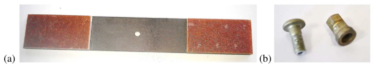
Open-Hole and Filled-hole:
These specimens were 25 mm wide and had a 4.2 mm diameter hole in their center (see Fig 2
(a)). The quality of machining was ensured by the use of a dedicated carbide tool and by placing
sacrificed plates on either side of the laminate in order to limit the damage generated at the
entrance and exit of the hole (particularly delamination at the end of the drill) [32]. The drilling
process was validated by checking that X-ray images of the holes revealed no delamination or
cracking at the edge of the hole. For filled hole specimens, the bolt (see Fig 2 (b)) was installed
according to the following parameters: screws and nuts following aeronautic standards
(Imperial size fasteners: IVD (ion vapor deposited) coated quenched and tempered Titanium
bolts and frangible cadmium plated steel nuts) low clearance; tightening torque imposed by the
fuse nut ≈ 2.3 N.m
3 Four notches were machined tangent to the hole, two on either side of the laminate () (Fig. 3).
The notches were oriented parallel to the loading direction. The cutting tool was a diamond disc
with a diameter of 20 mm and a thickness of 0.6 mm. The notches were characterized by their
length, width and depth. Several geometries (depth and length) were tested and will be specified
later.
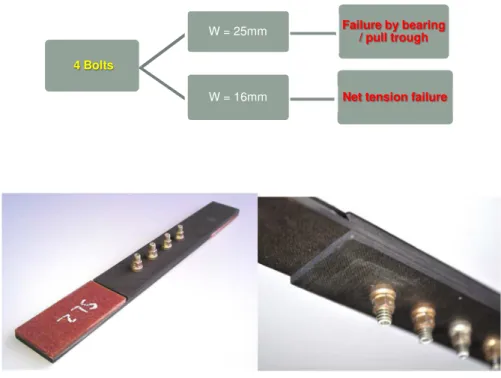
Single-lap shear and double-lap-shear reference specimens: The specimens are shown Fig.4. It comprises:
• 4 Bolts and nuts following aeronautic standards installed without sealant and no treatment applied to the surfaces, low clearance.
• Two specimen widths: 25 mm and 16 mm for two different failure modes (combined bearing / pull-through and net tension failure, respectively, see Fig. 4).
Notched single-lap and double lap-shear:
The overall geometry of these specimens was identical to that of “single-lap shear” ones. The
machining process was modified in order to achieve unidirectional notches and thus avoid
weakening the bearing resistance of the holes. The process was then more complex and required
the use of carbide milling cutters of very small diameter (1 mm) to generate the notches tangent
to the hole. The cutting parameters were: cutting speed 84 m.min-1 and feed per tooth 260
mm.min-1. Several configurations were tested for each width and for each lay-up (18 test
pieces). The precise configurations tested (and the acronyms chosen to represent them) were
the following:
• Notches on the outer face of each half-part of the specimen and only on one side of the hole (code SL-O).
4 Only the one hole concerned (code SL-O-E) corresponding to the most loaded
(external one)
• Notches on both sides of each half-specimen (ext. and int.) of the specimen (code SL-OI)
All the holes concerned (code SL-OI-A)
Notches as for open and filled hole, symmetrical with respect to the most loaded
hole and made on both sides of each half-specimen (SL-OI-E-D), only for
symmetrical layup 2 (see Fig 5 (c))
• For notched double-lap shear specimens (2 specimens only), the overall geometry of these specimens is identical to the unnotched specimens and the geometry and location
of the notches is identical to single lap shear specimens SL-OI-E-D (see Fig 5 (c)).
The code for these specimens is DL-NCS.
Matrix of tests.
The matrix of tests (incomplete for practical industrial reasons due to the exploratory nature
of this study) is given in Table 1 with the number of specimens tested.
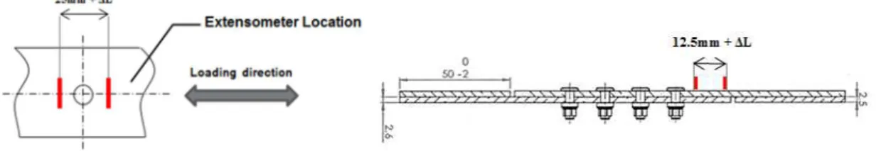
Measurement method:
The strain was measured using an INSTRON 2620-201 dynamic extensometer +/- 5mm. The
extensometer was fixed directly to the surface of the test piece, according to the plane of the
test piece and on either side of the hole (Fig. 7). The strain values were recorded by a dynamic
acquisition system independent of the machine's electronic card.
3. Results for Oriented specimens
3.1 Open hole and filled hole
Three non-machined specimens were tested and the results showed low dispersion (average
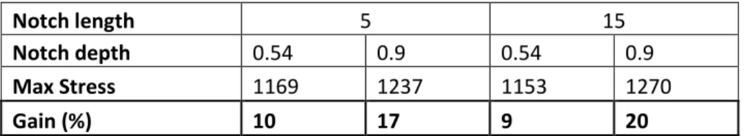
5 vs an open hole test and Table 2 gives the geometry of the 4 different notches, with the gains
obtained. The failure patterns are not provided in this paper but they differed little according to
whether notches were present or not and were similar to those presented in [27]. Tests showed
that the process made it possible to obtain significant gains in tension. These gains were greatest
when the notch was long and deep. The loss of modulus was practically constant and limited
for all the notch geometries tested (from -8% to -10%). A particular behavior was observed
when the "notched 15 * 0.9 mm" test piece was tested. Its initial modulus was identical to that
of the other "notched" test specimens but it quickly became non-linear (≈ 40% σmax) and a
significant jump in the measured strain was observed. This specimen presented the largest
notches and the failure scenario was affected early but the gain remained significant (+ 20%).
Figure 8 shows the test results for test specimens with or without 5 * 0.9 mm notches, filled or
not. A drop can be observed in the static strength of the filled specimen. In order to understand
how the insertion of the fixation caused the decrease in this behavior of the specimens, an
additional test was carried out: a bolt was installed on a test piece but without a tightening nut
(nut not accosted) in order to prevent any preloading of the screw during the test. The static
behavior of the test piece then returned to that of an open hole specimen. At first glance, the
reduction observed on the filled hole coupon appeared to come from the compression (σ33) of
the area located under the screw head or the nut. This result is in agreement with the results of
[32], which show a decrease in splitting tangent to the hole when the applied preload increases.
Note the excellent resistance of the "notched" test specimens compared to that of their
counterparts that were simply drilled. It is likely that the machining compensated for the closure
of the splitting due to tightening. It is interesting to note that, for the notched specimens, the
modulus was almost identical whether the test piece was filled or not, whereas it was different
without the notches.
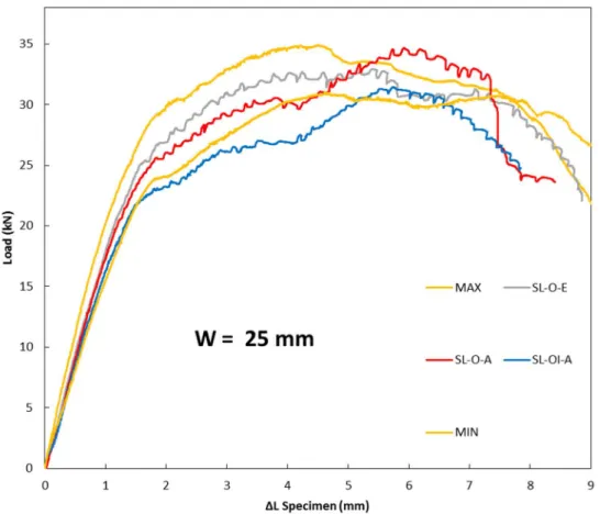
6 After having carried out a series of tests on tensile test pieces, the objective here was to find out
if the increase in strength with artificial splitting could be observed within bolted assemblies. It
is recalled that two widths of test pieces were considered in order to vary the failure modes (W
= 25 mm and W = 16 mm). With this layup we observed significant dispersion concerning the
moduli and the overall monotonous behavior (Figs. 9 and 10). The net stress (in the section of
the hole) at failure was close to 640 MPa when W = 25 mm and close to 910 MPa when W =
16 mm. Also, only the MIN-MAX behaviors observed were plotted in these two cases. The
overall failure of the non-notched test pieces occurred according to the modes expected by the
width pre-sizing and was similar to that of test pieces with notches (Fig 11). The two failure
modes observed were as follows:
• Failure in net section of the last row of fasteners + shear-out for the W = 16 mm specimens. Failure occurred randomly in the fixed or mobile half-specimen. Regarding
the shear-out, the 0° fiber bands were not tangent to the hole but approximately in the
middle of the net section (Fig 11 right).
• Pull-through failure and bearing of the four fasteners for the specimen that was 25 mm wide (Fig 11 left).
The notch process did not work on this configuration with oriented stacking. This remark is
valid for both widths considered. The least notched test pieces (SL-O-E & SL-O-A) showed no
apparent variation in their mechanical characteristics (Figs. 9 and 10) (results within the
dispersion of the test). In addition, the specimen having notches on each side of the half test
pieces (SL-IO-A) underwent a strength decrease, its bearing ability being weaker. For this
layup, the "double-notched" configuration was not tested.
4. Results for Quasi-Isotropic specimens
7 The behavior of the open hole reference specimens was almost linear up to the maximum
load, with little dispersion. A small plateau was observed before the final brutal rupture. The
average value at breaking was 710 MPa. All the configurations of notches gave a significant
gain (see Table 3). The results show that the traction gains were greater when the notch was
deep (+ 21.8%). In this last case, the loss of modulus was only -7.5%.
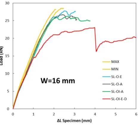
4.2 Notched single lap-shear specimens
For the reference specimens, the dispersion appeared to be very low during these tests. The
failure stress (in net section) was close to 655 MPa when W = 25 mm and close to 670 MPa
when W = 16 mm. The MIN-MAX behaviors noted on the test specimens are plotted in Figs.
12 and 13. The test pieces failed in the net section of the last fastener in the row (section bearing
the most stresses σ11).
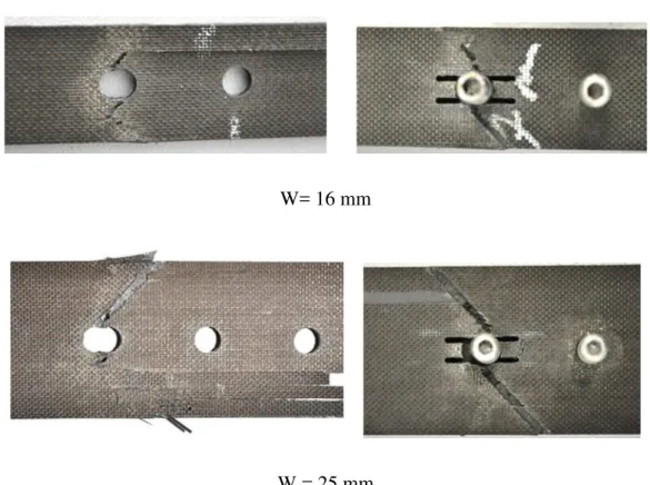
Unlike those with oriented stacking, the quasi-isotropic specimens showed no bearing or
pull-through breakages. The failure started at the edge of the hole and propagated at ± 45°. In
addition, significant and constant shear-out of the outer ply at 0° was observed, which stopped
tangentially at the head of the screw or the nut (Fig. 14).
It was observed that the notch process did not work on this configuration with quasi-iso layups
either. This remark is valid for the two widths considered. The least notched test pieces
(SL-O-E & SL-O-A) showed no apparent variation in their mechanical characteristics (results within
the dispersion of the test). In addition, the test piece having notches on each side of the half test
pieces (SL-IO-A) underwent a strength decrease, its bearing ability being weaker.
In the study of this layup, we were able to test the "double-notched / SL-OI-E-D" configuration.
The process did not work at all on test pieces of width W = 25 mm, the resistance to bearing /
8 width W = 16 mm, no variation in the tensile strength was observed (values within the
dispersion of the test) (Figs. 12 and 13).
The overall failure of the assemblies occurred in the net section of the last hole (the most loaded
section). For the notched specimens (SL-OE / SL-OA / SL-OI-A), no bearing or pull-through
failure was observed and the failure began at the edge of the hole then propagated to the free
edge with an angle of ± 45°. Shear-out of the ply at 0° occurred on the surface (Figure 14).
Concerning the “double notched” test pieces (SL-OI-E-D), failure occurred (Fig. 15):
• in net section, propagation at ± 45° from the edge of the hole with shear-out of the ply at 0° on the surface for specimens W = 16mm.
in bearing with a sudden ejection of a fastener for specimens W = 25mm.
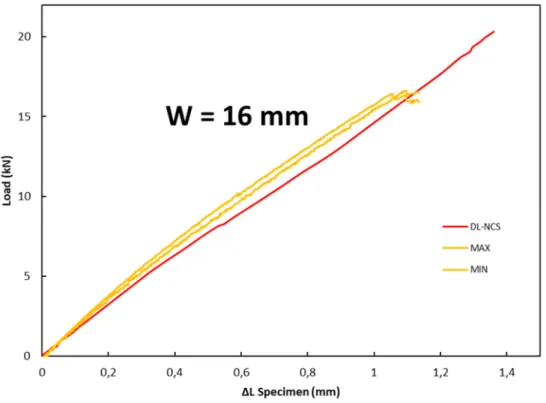
4.3 Notched double lap-shear specimens
For the reference specimens, the dispersion appeared to be very low during these tests. The
failure stress (in net section) was close to 684 MPa when W = 25 mm and close to 661 MPa
when W = 16 mm. The MIN-MAX behaviors noted on the test specimens are plotted in Figs.
16 and 17.
The notch process works very well on this configuration and very significant increase (+22.5
%) in the tensile strength for W = 16 mm and +4.5 % for W=25 mm are observed. The failure
modes also vary slightly between the reference and “notched” test pieces (Fig. 18). The overall
failure of the assembly occurs in net clean section of the last hole of the half-specimen in all
cases. However, there is no shear-out of the 0 ° ply outside the central half-specimen of the
"notched" test pieces. In addition, the failure of the “notched” specimens occurs clearly with a
propagation at ± 45 ° from the edge of the hole while the failure of the reference specimen is
more complex, with a failure pattern with “V” shape. The increase in strength observed in this
9
5. Conclusions
An original and explorary study was carried out on the effect of artificial splitting with notches
machined at the edge of the hole for 2 layups: oriented and quasi-isotropic, and 4 specimen
geometries: open/filled holes and single/double lap shear specimen. A significant increase in
static tensile strength was observed for open, filled hole and double lap shear specimens with
notches (up to + 20%). This confirms the generally beneficial effect of splitting on the static
resistance and it could be implemented either through stacking sequences that naturally favor it
in fatigue or directly by means of the recommended machining, which has been patented by
Airbus [34]. The methodology could be used to improve the resistance of a load-bearing
structure loaded in a main direction, on which other substructures transmitting less stress could
be fixed, or for secondary structures. The notch process was not effective in single lap shear
tests with 4 fasteners despite the large number of machining variants tested. In some cases, it
even decreased the strength of the assembly, which limits the scope of the innovation. Even if
this first study must be confirmed by more extensive testing, this study is of scientific interest
as it shows, once again, the very particular structural behavior of composites, even from coupon
scale.
References
[1] Bouvet C, Castanié B, Bizeul M, Barrau JJ. Low velocity impact modelling in laminate
composite panels with discrete interface elements. Int J. Sol Struct 2009;46(14-15):2809-2821
[2] Tan W, Falzon BG, Chiu LNS, Price M. Predicting low velocity impact damage and
Compression-After-Impact (CAI) behaviour of composite laminates. Comp Part A
2015;71:212-226.
[3] Adam L, Bouvet C, Castanié B, Daidié A, Bonhomme E. Discrete ply model of circular
10 [4] Wisnom MR. On the high compressive strains achieved in bending tests on unidirectional
carbon-fibre/epoxy. Comp Sci Tech 1992:43(3):229-235
[5] Castanié B, Crézé S, Barrau JJ, Lachaud F, Risse L. Experimental analysis of failures in
filled hole compression tests of carbon/epoxy laminate. Comp Struct 2010;92 (5):1192-1199.
[6] Serra J, Pierré JE, Passieux JC, Périé JN, Bouvet C, Castanié B. Validation and modeling
of aeronautical composite structures subjected to combined loadings: The VERTEX project.
Part 1: Experimental setup, FE-DIC instrumentation and procedures. Comp Struct
2017;179:224-244.
[7] Serra J, Pierré JE, Passieux JC, Périé JN, Bouvet C, Castanié B, Petiot C. Validation and
modeling of aeronautical composite structures subjected to combined loadings: The VERTEX
project. Part 2: Load envelopes for the assessment of panels with large notches Comp Struct
2017;180: 550-567.
[8] Mar JW, Lin KY. Characterization of Splitting Process in Graphite/Epoxy Composites. J
Comp Mat 1979;13:278-287.
[9] Goree JG, Wolla JM. Longitudinal splitting in Unidirectional composites, Analysis and
Experiments. NASA Contractor Report 3881, 1985
[10] Goree JG, Wolla JM. Experimental Evaluation of Longitudinal Splitting in Unidirectional
Composites. J Comp Mat 1987;21:49-67.
[11] Bazhenov SL. Longitudinal splitting in unidirectional fibre-reinforced composites with an
open hole. Comp Sci Tech 1998;58(1):83-89.
[12] Tan JLY, Deshpande VS, Fleck NA. Failure mechanisms of a notched CFRP laminate
11 [13] Ramani S, Williams D. Notched and unnotched fatigue behavior of angle ply
graphite-epoxy composites. NASA TM X-73, 191, 1976.
[14] Daken HH, Mar JW. Splitting initiation and propagation in notched unidirectional
graphite/epoxy composites under tension-tension cyclic loading. Comp Struct
1985;4(2):111-133.
[15] Jen MH, Hsu J. Residual strength in notched composite materials. Int J Fat 1990;12:267-274.
[16] Spearing SM, Beaumont PWR. Fatigue damage mechanics of composite materials. I:
Experimental measurement of damage and post-fatigue properties . Comp Sci Tech
1992;44(2):159-168.
[17] Wang C, Shin C. Residual properties of notched [0/90]4s AS4/PEEK of composite
laminates after fatigue and re-consolidation. Comp Part B 2002;33:67-76.
[18] Shin CS, Wang C. A comparison of as-fatigue and re-consolidation residual properties for
notched quasi-isotropic [0/45/90/ 2 45]2S and cross-ply [0/90]4S AS4/PEEK composite
laminates. Comp Part A 2002;33:1519–1528.
[19] Choi SW, Hahn HT, Shyprykevich, P. Damage development in notched composite
laminates under compression-dominated fatigue. Comp Sci Tech 2002;62: 851–860.
[20] Kawai M, Shiratsuchi T. Vanishing notch sensitivity approach to fatigue life prediction of
notched cross-ply CFRP laminates at room temperature. J Comp Mat 2012;46(23):2935–2950.
[21] Nixon-Pearson OJ, Hallett SR. An investigation into the damage development and residual
strengths of open-hole specimens in fatigue. Comp Part A 2015;69:266–278.
[22] Cui YL. Mechanics of splitting in orthotropic materials. Int J. Sol Struct
12 [23] Wisnom MR, Chang FK. Modelling of splitting and delamination in notched cross-ply
laminates. Comp Sci Tech 2000;60(15):2849-2856.
[24] Iarve EV, Mollenhauer D, Kim R. Theoretical and experimental investigation of stress
redistribution in open hole composite laminates due to damage accumulation. Comp Part A
2005;36:163-171.
[25] Van der Meer FP, Sluys LJ. A phantom node formulation with mixed mode cohesive law
for splitting in laminates. Int J Fract 2009;158(2):107-124.
[26] Hallett SR, Green BG, Jiang WG, Wisnom MR. An experimental and numerical
investigation into the damage mechanisms in notched composites Comp Part A
2009;40:613-624.
[27] Achard V, Bouvet C, Castanié B, Chirol C. Discrete ply modelling of open hole tensile
tests Comp Struct 2014:113;369-381.
[28] Le MQ, Bainier H, Néron D, Ha-Minh C, Ladevèze P. On matrix cracking and splits
modeling in laminated composites Comp Part A 2018;115:294-301.
[29] Lee J, Soutis C. Measuring the notched compressive strength of composite laminates:
specimen size effects Comp Sci Tech 2008;68:2359-2366.
[30] Bao H, Liu G. Progressive failure analysis on scaled open-hole tensile composite
laminates. Comp Struct2016;150: 173-180.
[31] Serra J, Bouvet C, Castanié B, Petiot C. Scaling effect in notched composites: The Discrete
Ply Model approach. Comp Struct 2016;148:127-143.
[32] Catche S, Piquet R, Lachaud F, Castanie B, Benaben A. Analysis of hole wall defects of
13 [33] Yan Y, Wen WD, Chang FK, Shyprykevich P. Experimental study on clamping effects on
the tensile strength of composite plates with a bolt-filled hole. Comp Part A
1999:30(10);1215-1229.
[34] Airbus Patent US20160023425 (A1)
Figures
(a) (b)
Fig. 1: Example of splitting around open hole ((a) reproduced from [13]) or notch ((b) reproduced from [8]).
14
(a) (b)
Fig. 2: Open Hole specimen (a) and bolt and nuts used for Filled hole specimens (b).
15
Fig. 4: Failure mode prediction and single-lap and double-lap shear specimen.
(a) (b)
(c)
Fig. 5: Half specimen notched on one side (a) and (b) (Code SL-O-A); all holes concerned and symmetric notches on the most loaded hole (Code SL-OI-E-D).
4 Bolts
W = 25mm Failure by bearing / pull trough
16 Fig. 6: Location of extensometer for coupons of single and double lap shear specimens.
Fig. 7: Tension tests results for open hole specimen with and without different notches
(oriented layup). 0 200 400 600 800 1000 1200 0 0,5 1 1,5 2 2,5 3
N
e
t
st
re
ss
e
s
(M
p
a
)
Strain (%)
Open-hole Notched 5*0,54mm Notched 5*0,9mm Notched 15*0,54mm Notched 15*0,9mm17 Fig. 8: Tension test results for open and filled hole specimens with and without notches 5*0.9
18 Fig. 9: Tension test results for single-lap shear specimens (W = 16 mm), (oriented layup).
19 Fig. 10: Tension test results for single-lap shear specimens (W = 25 mm), (oriented layup).
Fig. 11: Failure Patterns of “notched” single lap shear specimens. Left, W = 25; right W = 16
20 Fig. 12: Tension test results for single-lap shear specimens (W = 16 mm), quasi-isotropic
layup.
Fig. 13: Tension tests results for single-lap shear specimens (W = 25 mm), quasi-isotropic
layup. 0 2 4 6 8 10 12 14 16 18 0 0,5 1 1,5 2 Lo a d ( k N ) ΔL specimen (mm) SL-OI-E-D MAX MIN SL-O-E SL-O-A SL-OI-A
W=25 mm
21 (a)
(b)
Figure 14. Failure modes of SL-O-A specimens W=16 mm (a) and W=25 mm (b), quasi-isotropic layup.
(a)
(b)
Figure 15. Failure pattern of SL-OI-E-D specimens W = 16 mm (a) and W = 25 mm (b), quasi-isotropic layup.
22 Fig. 16: Tension test results for double-lap shear specimens (W = 16 mm), quasi-isotropic
layup.
Fig. 17: Tension tests results for double-lap shear specimens (W = 25 mm), quasi-isotropic
23
W= 16 mm
W = 25 mm
Figure 18. Failure mode patterns for double lap shear specimens: reference specimens (left)
and notched specimens (right); W=16mm (upper) & W=25mm (lower)
Tables
Oriented Quasi-Isotropic Reference Open Hole 3 3 Reference Filled Hole 3 3
Notched Open Hole 4 3
Notched Filled Hole 1 0 Reference Single Lap Shear 3 3 Notched Single Lap Shear 6 6 Reference Double Lap Shear 0 6 Notched Double Lap Shear 0 2
24
Notch length 5 15
Notch depth 0.54 0.9 0.54 0.9
Max Stress 1169 1237 1153 1270
Gain (%) 10 17 9 20
Table 2: Geometry of notches and static gains.
Notched specimens
Length (mm) 5
Depth (mm) 0.65 0.65 1
Net max stress (Mpa) 781.4 745.6 863.7
Gain (%)(/open-hole) +10.1 +5.1 +21.8
Longitudinal modulus (Gpa) 511 506 498
Variation in modulus (%) (/open-hole) -5 -6 -7.5
![Fig. 1: Example of splitting around open hole ((a) reproduced from [13]) or notch ((b) reproduced from [8])](https://thumb-eu.123doks.com/thumbv2/123doknet/12421204.333786/15.892.258.683.441.941/fig-example-splitting-open-hole-reproduced-notch-reproduced.webp)