STRENGTHENING OF REINFORCED CONCRETE TWO-WAY
SLABS USING MECHANICALLY FASTENED FRP SYSTEMS
RENFORCEMENT DE DALLES ARMEES BIDIRECTIONNELLES
AVEC DES SYSTEMES DE PRF ATTACHES MECANIQUEMENT
These de doctorat es sciences appliquees Specialite: genie civil
Walid ELSAYED Sherbrooke (Quebec), CANADA January 2008
1*1
Library and
Archives Canada
Published Heritage
Branch
395 Wellington Street Ottawa ON K1A0N4 CanadaBibliotheque et
Archives Canada
Direction du
Patrimoine de I'edition
395, rue Wellington Ottawa ON K1A0N4 CanadaYour file Votre reference ISBN: 978-0-494-37968-4 Our file Notre reference ISBN: 978-0-494-37968-4
NOTICE:
The author has granted a
non-exclusive license allowing Library
and Archives Canada to reproduce,
publish, archive, preserve, conserve,
communicate to the public by
telecommunication or on the Internet,
loan, distribute and sell theses
worldwide, for commercial or
non-commercial purposes, in microform,
paper, electronic and/or any other
formats.
AVIS:
L'auteur a accorde une licence non exclusive
permettant a la Bibliotheque et Archives
Canada de reproduire, publier, archiver,
sauvegarder, conserver, transmettre au public
par telecommunication ou par Plntemet, prefer,
distribuer et vendre des theses partout dans
le monde, a des fins commerciales ou autres,
sur support microforme, papier, electronique
et/ou autres formats.
The author retains copyright
ownership and moral rights in
this thesis. Neither the thesis
nor substantial extracts from it
may be printed or otherwise
reproduced without the author's
permission.
L'auteur conserve la propriete du droit d'auteur
et des droits moraux qui protege cette these.
Ni la these ni des extraits substantiels de
celle-ci ne doivent etre imprimes ou autrement
reproduits sans son autorisation.
In compliance with the Canadian
Privacy Act some supporting
forms may have been removed
from this thesis.
Conformement a la loi canadienne
sur la protection de la vie privee,
quelques formulaires secondaires
ont ete enleves de cette these.
While these forms may be included
in the document page count,
their removal does not represent
any loss of content from the
thesis.
Canada
Bien que ces formulaires
aient inclus dans la pagination,
il n'y aura aucun contenu manquant.
A new technique for strengthening reinforced concrete (RC) slabs using FRP compos-ites is investigated. It is referred to as the mechanically fastened (MF) technique, which is based on fixing FRP materials to concrete using closely spaced powder-actuated fas-teners. A special FRP material, known by the trade name SAFSTRIP®, is used in this method. It is characterized by a high bearing strength as well as a high tensile strength. This new technique is very rapid compared to the conventional bonded FRP techniques. Furthermore, it allows for immediate use of the structure after completion of the installa-tion process. In addiinstalla-tion, unlike the bonded system, the use of the MF system results in a desirable ductile behaviour of the strengthened structure. The commonly used fasten-ers in this technique are embedded into the concrete using a powder actuated fastening
"gun". The shot of this fastener is very strong and may sometimes cause initial cracking or concrete spalling or may locally damage the FRP if the fastener is overdriven. To overcome these problems we have proposed a new fastener based on screwing rather than shooting the fastener into the concrete. This screwed fastener has a better anchorage into the concrete, and displays a much better performance.
This study attempts to investigate the behaviour of RC slabs strengthened in flexure with the mechanically fastened FRP system. Two series of large-scale reinforced concrete slabs are tested. The first series is comprised of five slabs without a cut-out, and measuring 2600 x 2600 x 120 mm; the second series consists of four slabs of the same dimensions with a central cut-out measuring 800 x 800 mm. In each series, one slab is left unstrengthened to serve as a reference while FRP strips are used to strengthen the remaining slabs. Different strengthening patterns are used with different spacings between fasteners. Also, the conventionally bonded strengthening technique is used for the sake of comparison. The mechanically fastened system is found to be an interesting alternative to the bonded system resulting in a rapid, economic, and effective system. The gained increases in ultimate capacities of the MF FRP-strengthened slabs range between 30 to 70% over those of the unstrengthened specimens. Moreover, the use of the MF system shows a desirable pseudo-ductile mode of failure.
strips mechanically fastened to concrete blocks are reported. Based on the results from these tests, new analytical models that describe the interfacial behaviour between the MF FRP and concrete substrate are developed. These models are referred to as "bearing-slip" models. Finite element models are then introduced to address the interfacial behaviour between the FRP strips and the concrete substrate for the MF FRP/concrete direct shear specimens. Results are presented in terms of ultimate load capacities and load-slip re-lationships. The numerical predictions are verified against the experimental data, and very good agreement is obtained. Based on this verification, the proposed bearing-slip models are subsequently used in finite element analyses to simulate the cases of RC beams and slabs strengthened with the MF system. Also, the theoretical part of this study is extended to include finite element modelling of bonded FRP-strengthened slabs. The interfacial behaviour between the FRPs and the concrete substrate is accounted for by using appropriate interfacial models. It is shown that the numerical models can be ap-plied to arbitrary FRP configurations, and can also accommodate both passive as well as prestressed FRP strengthening schemes. Results are presented in terms of load-deflection relationships, ultimate load capacities, failure modes, and interfacial slip and stress distri-butions. When compared to test results reported in the literature, the analysis is shown to lead to very good predictions.
Une nouvelle technique pour le renforcement de dalles en beton arme avec des com-posites en polymeres renforces de fibres (PRF) est etudee. Cette technique est connue sous le nom de la methode d'attache mecanique (mechanically fasted method) qui est basee sur la fixation du composite sur le beton en utilisant des attaches etroitementes alignes. Un PRF special (SAFSTRIP®) est utilise pour cette methode qui se distingue par sa haute resistance a l'ecrasement et a sa haute resistance a la tension. Cette tech-nique est plus rapide d'execution que la techtech-nique conventionnelle. En outre, elle permet l'utilisation immediate des dalles apres avoir termine l'installation du renforcement. De plus, le nouveau system de pose du composite donne un comportement ductile souhaitable a la structure renforce. Les attaches les plus generalement utilises dans cette technique sont incorporees dans le beton par un pistolet. Le tir de ces attaches est tres fort, il peut causer des fissures dans le beton ou degrader la surface ou encore endommager le PRF si 1'attache est tiree trop fort. Pour eviter ce probleme, nous avons propose une nouvelle facon d'attacher le composite en vissant les attaches au lieu de les tires dans le beton par pistolet. Ce vissage des attaches a un meilleur ancrage dans le beton, et donne une meilleure performance.
Cette etude traite du comportement flexionnel des dalles en beton arme renforcees par des composites attaches mecaniquement. Deux series de dalles a grandeur reelles sont testees. La premiere serie se compose de cinq dalles pleines de dimensions 2600 x 2600 x 120 mm, la deuxieme serie consiste en quatre dalles de meme dimension que la premiere serie avec une ouverture au milieu de dimension 800 x 800 mm. Dans chaque serie, une dalle est non-renforcer pour servir de dalle de reference. Differents modeles de renforcement sont utilises avec differents espacements entre les attaches. Aussi, la tech-nique conventionnelle est utilisee a des fins de comparaison. La nouvelle techtech-nique est une interessante alternative, du faite qu'elle est rapide, economique et efficace. L'augmentation des la capacite portante de dalles renforcees, par cette technique par rapport a la dalle de reference, est de 30 a 70%. D'ailleurs, l'utilisation de la nouvelle technique montre un mode de rupture pseudo-ductile souhaitable.
direct des PRF attaches mecaniquement a des blocs de beton. Base sur ces resultats, des modeles analytiques qui decrivent le comportement de l'interface entre le beton et le PRF sont developpes. Ces modeles sont appeles modeles de glissement des attaches (bearing-slip models). Une etude par element finis a ete faite, pour bien modeliser l'interface entre le beton et le PRF, sur les specimens testes par cisaillement direct. Les resultats sont presentes en termes de capacite de chargement ultime et de relation glissement-chargement. Les resultats numeriques sont en tres bon accord avec les resultats experimentaux. Base sur ces resultats, le modeles de glissement propose est introduit dans l'analyse par element finis des exemples de poutres et de dalles renforcees par la nouvelle technique. Aussi une partie theorique est introduite pour les dalles renforcees par la nouvelle technique, afin de verifier l'analyse par la methode des elements finis. Le com-portement de l'interface entre le beton et PRF est explique par un modele d'interface approprie. On a montre que les modeles numeriques peuvent etre appliques a n'importe quelles configurations des PRF, et peuvent etre appliques pour le schema de renforcement passif ou precontract. Les resultats sont presentes en termes de relation charge-deflexion, de capacite portante, de modes de ruptures, et de glissement et de distributions de con-traintes. Les resultats numeriques donnent de bonnes predictions comparees aux resultats experimentaux reportes dans la litterature.
Acknowledgements
This thesis is the result of four years of work where I have been accompanied and supported by many people. It is a pleasant aspect that I now have the opportunity to express my gratitude to all of them.
I am deeply indebted to my supervisor Professor Kenneth W. Neale whose help, guid-ance, advice and support helped me in all the duration of the research. I have come to know Professor Neale as a sympathetic and principle-centred person. His enthusiasm and integral view on research and his mission for providing only high-quality supervision has made a deep impression on me. I owe him gratitude for having me shown this way of research and appreciate how much I have learned from him. I am very grateful for the excellent suggestions during his meticulous and tireless supervising.
I would like to also extend my appreciation and gratitude to Dr. Usama A. Ebead, who in essence acted as my co-supervisor, for his stimulating suggestions and encouragement provided throughout the conduct of this Ph.D. work. Dr. Ebead always kept an eye on the progress of my work and was always available when I needed his advice.
I would like to thank Mr. Marc Demers for his technical expertise and advice, and for his efforts in executing the experimental aspects of this project. Also, the hard work provided by Mr. Claude Aube during the construction and testing phases of this project is greatly appreciated.
Many colleagues from the University of Sherbrooke supported me in this research work. I want to thank them for all their help, support, interest and valuable hints. I am especially obliged to Mr. Hussien Abdel Baky.
This research was funded by the Natural Sciences and Engineering Research Council of Canada (NSERC) and the Canadian Network of Centres of Excellence on Intelligent Sensing for Innovative Structures (ISIS Canada). The support of these programs is grate-fully acknowledged. I am also thankful to Strongwell Inc. for providing the SAFSTRIP® FRPs.
Contents
1 Introduction 1 1.1 General 1 1.2 Scope 3 1.3 Research Objectives 4 1.4 Outline 4 2 Literature Review 5 2.1 Introduction 5 2.2 FRP Composite Materials 52.3 Bonded FRP Strengthening Systems 8 2.3.1 Strengthening of RC Beams Using FRP Composites 10
2.3.2 Modelling of FRP-Strengthened RC Beams 12 2.3.3 FRP/Concrete Interfacial Behaviour 13 2.3.4 Failure Modes for FRP-Strengthened RC Structures 16
2.3.5 Modelling of FRP/Concrete Interface 18 2.3.6 Strengthening of RC Slabs Using Bonded FRPs 20
2.3.6.1 Punching Shear Strengthening of RC Slabs 20
2.3.6.2 Flexural Strengthening of RC Slabs 22 2.3.6.3 Strengthening of RC Slabs With a Cut-Out 25
2.3.6.4 Modelling of FRP-Strengthened RC Slabs 26
2.4 Mechanically Fastened FRP Strengthening System 28
2.4.1 General 28 2.4.2 Mechanically Fastened FRP-Strengthened RC Beams 29
2.5 Summary 33 3 Experimental Program 35 3.1 Introduction 35 3.2 Materials 36 3.2.1 Concrete 36 3.2.2 Reinforcing Steel 37
CONTENTS
3.2.4 Fasteners and Washers 38 3.3 Direct Shear Test Specimens 40
3.3.1 Test Specimens 40 3.3.2 Construction Procedure of FRP/Concrete Joints 42
3.3.2.1 Fastening FRP Composites to Concrete 42 3.3.2.2 Bonding FRP Strips to Concrete 43 3.3.3 Test Setup for FRP/Concrete Joints 43
3.4 FRP-Strengthened Concrete Slabs 45
3.4.1 Test Specimens 45 3.4.2 Construction of the Specimens 50
3.4.2.1 Fastening FRP Strips to Concrete Slabs 51 3.4.2.2 Bonding FRP Strips to Concrete Slabs 52
3.4.3 Instrumentation 52 3.4.4 Test setup 56
4 Experimental Results and Discussion 58
4.1 Introduction 58 4.2 Direct Shear Test Results 58
4.2.1 Fastened FRP/Concrete Joints 59 4.2.1.1 FRP/Concrete Joints with One Fastener 59
4.2.1.2 FRP/Concrete Joints with Multiple Fasteners 61
4.2.2 Bonded FRP/Concrete Joints 67 4.2.3 Proposed Bearing-Slip Models for the MF FRP/Concrete Interface 67
4.3 FRP-Strengthened RC Slabs 69 4.3.1 FRP-Strengthened Slabs Without a Cut-Out (SW Series) 69
4.3.1.1 Load Capacities and Deformational Characteristics . . . . 69
4.3.1.2 Cracking Behaviour 77 4.3.1.3 Concrete, Steel, and FRP Strains 77
4.3.1.4 Ductility and Energy Absorption 81 4.3.2 FRP-Strengthened Slabs with a Cut-Out (SO Sreies) 81
4.3.2.1 Load Capacities and Deformational Characteristics . . . . 82
4.3.2.2 Cracking Behaviour 87 4.3.2.3 Concrete, Steel, and FRP Strains 88
4.3.2.4 Ductility and Energy Absorption 91
4.4 Conclusion 92
5 Numerical Analysis 94
5.1 Introduction 94 5.2 Material Models for Concrete, Steel and FRP 96
5.3 FRP/Concrete Interface 98 5.3.1 Bearing-Slip Model for MF FRP System 98
5.4 Geometrical Modelling 102 5.4.1 Geometrical Modelling of FRP/Concrete Joints and FRP-Strengthened
Beams 102 5.4.2 Geometrical Modelling of FRP-Strengthened Slabs 103
5.5 Numerical Results and Discussion 105 5.5.1 FRP/Concrete Joints 105 5.5.2 MF FRP-Strengthened Concrete Beams 108
5.5.2.1 Maximum Moment Capacities and Failure Modes 110 5.5.2.2 Slip Profiles Along the FRP/Concrete Interface 110 5.5.2.3 Shear Forces in Fastener Profiles Along the FRP/Concrete
Interface 113 5.5.3 MF FRP-Strengthened Concrete Slabs 117
5.5.3.1 Maximum Load Capacities and Failure Modes 117 5.5.3.2 Slip Profiles Along the FRP/Concrete Interface 120 5.5.3.3 Shear Forces in Fastener Profiles Along the FRP/Concrete
Interface 123 5.5.4 Bonded FRP-Strengthened Concrete Slabs 125
5.5.4.1 Load Capacities and Deformational Characteristics . . . . 127
5.5.4.2 Modes of Failure 132 5.5.4.3 Interfacial Shear Stress and Slip Profiles 132
5.5.4.4 Tensile Stress Profiles Along the FRPs 136
5.6 Conclusion 141
6 Conclusions and Recommendations 142
6.1 Introduction 142 6.2 Conclusions from Experimental Investigations 142
6.2.1 Direct Shear Tests 142 6.2.2 FRP-Strengthened Slabs 143 6.3 Conclusions from Analytical Investigations 144
6.3.1 Mechanically Fastened FRP Strengthening System 145
6.3.2 Bonded FRP Strengthening System 145
6.4 Recommendations for Future Work 146
Appendices 148
LIST OF FIGURES
List of Figures
2.1 Examples of FRP strengthening for concrete structures [Enochsson, 2005] . 8 2.2 Strengthening of a concrete silo with FRP composite wrap system
[Enochs-son, 2005] 9 2.3 Strengthening of a bridge girder using precured CFRP plates [Enochsson,
2005] 10 2.4 Strengthening of a bridge joint with NSMR system [Enochsson, 2005] . . . 11
2.5 Cracking behaviours and final failure modes for FRP-strengthened beams
[Wu and Yin, 2003] 17 2.6 Debonding failure modes for FRP-strengthened beams [Teng et al., 2004] . 18
2.7 FRP strengthening of slab column connection [Ebead, 2002] 21 2.8 Punching shear failure of CFRP-strengthened slab [Harajli and Soudki, 2003] 22
2.9 Installation of external CFRP stirrups [Binici and Bayrak, 2005] 23 2.10 Debonding failure of FRP-strengthened slab [Limam et al., 2003] 24 2.11 Reinforced concrete slab strengthened with prestressed FRP sheets
[Long-worth et a l , 2004] 25 •2.12 The test setup used by Enochsson (2005) 26
2.13 Mechanically fastening of FRP strips to concrete surface 28 2.14 (a) Bearing failure at the FRP plate end (b) FRP delamination at mid-span
of MF FRP-strengthened beam [Lamanna et a l , 2004b] 30 2.15 Load-deflection comparison between the control beam and the MF
FRP-strengthened beams [Bank et al., 2003] 31 2.16 Load per fastener versus concrete strain according to (a) Model 1 and (b)
Model 2 [Lee et al., 2007] 32 2.17 Plots of moment versus deflection curves predicted by [Lee et al., 2007] . . 33
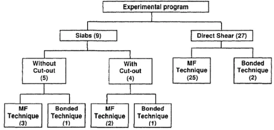
3.1 Description of the experimental program and the number of specimens . . 36
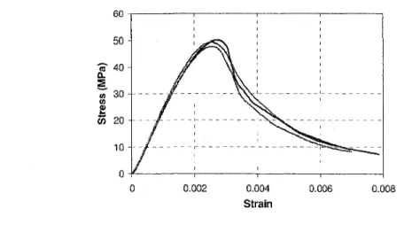
3.2 Representative results for the stress-strain relationship of concrete 37
3.3 Stress-strain relationships for the steel reinforcement 38 3.4 Stress-strain relationships for the FRP composites 39
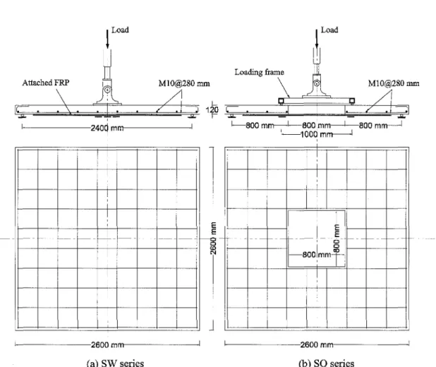
3.5 Test specimens of the FRP/concrete joints 40 3.6 Test setup for the direct shear application 44 3.7 Principal sketch of test setup and construction for SW and SO series . . . 47
3.9 Arrangement of FRP strips for SO series (dimensions in mm) 49
3.10 Construction of SW series specimen 51 3.11 Fastening FRP strips to concrete (a) drilling holes, (b) screwing fasteners
into the pre-drilled holes 52 3.12 Bonding FRP strips to concrete; applying adhesive layer (a) to concrete,
(b) to the FRP strip, (c) attaching FRP strip to concrete and (d) finishing 53 3.13 Typical strain gauge locations (concrete and steel reinforcement) for (a)
SW and (b) SO series (dimensions in mm) 54 3.14 Typical FRP strain gauge locations for (a) SW and (b) SO series
(dimen-sions in mm) 55 3.15 Typical potentiometer locations for (a) SW and (b) SO series (dimensions
in mm) 56 3.16 Test setup for the slab specimens (a) without cut-out, (b) with cut-out . . 57
4.1 Load-slip profiles for FRP/concrete joints with one fastener 59
4.2 Load-slip profiles for specimens SC01 and ST01 60 4.3 Load-slip profiles of the FRP/concrete joints attached with different
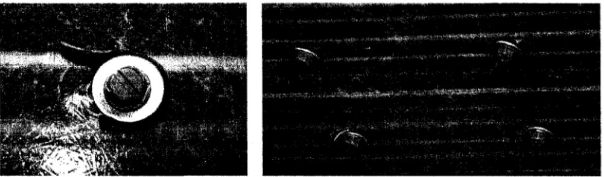
num-ber of (a) shot fasteners and (b) screwed fasteners 62 4.4 Fastener pullout off the concrete block for Specimen SH06, (b) FRP bearing
failure for specimens SC03 and SC04 64 4.5 Strain profiles along the FRP strip for specimens (a) SH06 and (b) SC06 . 64
4.6 Load-slip comparison between specimens SC01 and SC02 65 4.7 Load-slip comparison between specimens SC06, SC09, and SC12 66
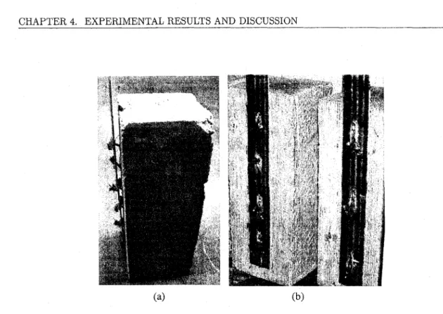
4.8 Failure modes for specimens (a) SC09 and (b) SC12 66 4.9 Bearing-slip models for (a) shot and (b) screwed fastener 68 4.10 Load-deflection relationships for SW series specimens 70 4.11 Crack pattern for SW series specimens after failure 72
4.12 Top corner cracks of Specimen SW-Ctrl 73 4.13 FRP debonding of Specimen SW-B-MS 73 4.14 FRP bearing and fastener bending of Specimen SW-F-MS-100 74
4.15 Specimen SW-F-MS-50 after second failure's occurrence 75
4.16 Specimen SW-F-SS-50 after failure 76 4.17 Load-strain relationships for concrete and steel for SW series specimens . . 78
4.18 FRP strain profiles for SW series specimens 80 4.19 Load-deflection relationships for SO series specimens 82
4.20 Crack pattern for SO series specimens 84 4.21 Concrete crushing of Specimen SO-Ctrl 85 4.22 FRP debonding initiation for Specimen SO-B 85
4.23 Specimen SO-F-1R-50 after failure 86 4.24 Bending of fasteners at the FRP strip end for Specimen SO-F-1R-50 . . . . 87
LIST OF FIGURES
4.25 Fastener pullout failure at the F R P strip end for SO-F-2R-50 88 4.26 Load-strain relationships for concrete and steel of SO series 89
4.27 F R P strain profiles for SO series specimens 90
5.1 The process of finite element analysis 95
5.2 Constitutive law of concrete 97 5.3 Bearing-slip models for the shot and the screwed fastener 99
5.4 Bond-slip models [Lu et a l , 2004] 100 5.5 Finite element models for the 2D analysis 104
5.6 Finite element models for the 3D analysis of strengthened slabs 105 5.7 Comparisons between numerical and experimental load-slip relationships
for direct shear specimens 107 5.8 Comparisons between numerical and experimental load-deflection
relation-ships for representative MF FRP-strengthened beams 112 5.9 Numerical interfacial slip profiles for representative MF FRP-strengthened
beams 114 5.10 Predicted profiles of fastener forces for representative MF FRP-strengthened
beams 116 5.11 Comparisons between numerical and experimental load-deflection
relation-ships for SW series specimens 118 5.12 Comparisons between numerical and experimental load-deflection
relation-ships for SO series specimens 119 5.13 Numerical interfacial slip profiles for SW series specimens 121
5.14 Numerical interfacial slip profiles for SO series specimens 122 5.15 Predicted profiles of fasteners forces for SW series specimens 124 5.16 Predicted profiles of fasteners forces for SO series specimens 125 5.17 FRP strengthening configurations of bonded FRP-strengthened slabs . . . 126
5.18 Load-deflection curves for Mosallam and Mosalam [2003] specimens . . . . 131 5.19 Load-deflection curves for Harajli and Soudki [2003]; Longworth et al.
[2004] specimens 131 5.20 (a) Slip and (b) interfacial shear stress profiles for Specimen SA1F15 tested
by Harajli and Soudki [2003] 133 5.21 (a) Slip and (b) interfacial shear stress profiles for Specimen C-REP-R1
tested by Mosallam and Mosalam [2003] 134 5.22 (a) Slip and (b) interfacial shear stress profiles for Specimen CFRP-F-0.35%
tested by Ebead and Marzouk [2004] 135 5.23 Slip profiles for Longworth et al. [2004] specimens 136
5.24 Tensile stress profiles along the FRP sheets for Ebead and Marzouk [2004]
specimens 137 5.25 Tensile stress profiles along the FRP sheets for Longworth et al. [2004]
5.26 Numerical results for Specimen SW-B-MS 139 5.27 Numerical results for Specimen SO-B 140 A.l Finite element model for an FRP-strengthened beam 148
A.2 Load-deflection curves for Lamanna et al. [2001] specimens 149 A.3 Interfacial slip profiles for Lamanna et al. [2001] specimens 149 A.4 Interfacial fasteners force profiles for Lamanna et al. [2001] specimens . . . 150
A.5 Load-deflection curves for Lamanna et al. [2004a] specimens 150 A.6 Interfacial slip profiles for Lamanna et al. [2004a] specimen 151 A.7 Interfacial fasteners force profiles for Lamanna et al. [2004a] specimen . . . 151
A.8 Load-deflection curves for Bank et al. [2003] specimens 152 A.9 Interfacial slip profiles for Bank et al. [2003] specimens 153 A. 10 Interfacial fasteners force profiles for Bank et al. [2003] specimens 153
A.11 Load-deflection curves for Lamanna et al. [2004b] specimens 154 A. 12 Interfacial slip profiles for Lamanna et al. [2004b] specimens 155
LIST OF TABLES
List of Tables
2.1 Mechanical properties of common fibres [Enochsson, 2005] 6 2.2 Typical mechanical properties of common resins [Enochsson, 2005] 7
3.1 Types of fastener 39 3.2 Configurations of the FRP/concrete joint specimens 41
3.3 Description of slab specimens 46
3.4 Slab configurations 46 3.5 Material properties of the slab specimens 50
4.1 Ultimate load capacities and modes of failure of the FRP/concrete joint
specimens 63 4.2 Test results for the SW series specimens 70
4.3 Maximum strains in FRP at failure for SW Series specimens 79
4.4 Test results for the SO series specimens 83 4.5 Maximum strains in FRP at failure for SO Series specimens 91
5.1 Comparison between experimental and numerical ultimate load capacities
of the FRP/concrete joint specimens 106 5.2 Material properties of MF FRP-strengthened RC beams 108
5.3 Configurations of MF FRP-strengthened concrete beams 109 5.4 Experimental and numerical results for maximum moment capacities and
modes of failure for MF FRP-strengthened beams I l l 5.5 Interfacial slip values along the interface for the beams tested by Lamanna
et al. [2004b] 113 5.6 Experimental and numerical results for maximum load capacities and
max-imum deflections for MF FRP-strengthened slabs 120 5.7 Material properties of bonded FRP-strengthened slabs 127 5.8 Specimen configurations of bonded FRP-strengthened slabs 128 5.9 Numerical and experimental results for bonded FRP-strengthened slabs . . 129
List of S y m b o l s
bc = Concrete member width
bf = F R P plate width
Ec = Elastic modulus of concrete
Efrp = Elastic modulus of F R P composite
Es = Elastic modulus of steel reinforcement
f'c = Concrete compressive strength
f'c = Concrete compressive strength
ffrpu = Tensile strength of FRP composite ft = Concrete tensile strength
fy = Steel yield strength
Ga = Shear modulus of bonding adhesive
Gc = Shear modulus of concrete
Gf = Total fracture energy of the bond-slip model
Cj = Fracture energy of the of the ascending branch of the bond-slip model's curve Ka = Stiffness of the adhesive layer
Kc = Elastic shear stiffness of concrete
K0 = Equivalent initial stiffness of the bond-slip model
S — Interfacial slip between FRP and concrete
Sb = Corresponding interfacial slip to the FRP bearing yield stress Sf — Corresponding interfacial slip to the FRP bearing strength Se = Elastic interfacial slip between FRP and concrete
Sp — Plastic interfacial slip between FRP and concrete
S0 — Corresponding interfacial slip to the maximum interfacial shear stress
ta = Thickness of the adhesive layer
tc = Thickness of the interfacial concrete layer
Pw = Width ratio of F R P plate to concrete member a = Bearing stress in F R P
ab — F R P bearing yield stress erf = FRP bearing strength
r = Interfacial shear stress between FRP and concrete
Chapter 1
Introduction
1.1 General
Reinforced concrete (RC) slabs can be divided into two main groups, namely beamless and beam supported slabs. Beamless slabs (flat slabs) are among the first types of reinforced concrete floor systems. Flat slabs have been used in different structural applications, such as floors and roofs of buildings, parking garages, walls of tanks, and offshore structures.
To economically reduce the amounts of materials used and to reduce storey heights for multi-storey structures, architects and engineers are constantly designing thinner slabs, which must satisfy both strength and serviceability requirements. When this tendency is combined with the fact that it is difficult to accurately model the behaviour of two-way slabs in practice, it can result in slab designs that are prone to excessive deflections or have insufficient flexural and/or shear capacity. In addition, several types of concrete structures in Canada and elsewhere, such as parking garages and infrastructures, are structurally deficient due mainly to deterioration and corrosion under harsh climates and the extensive use of de-icing salts [ISIS-Canada, 2001]. Additionally, increased service loads, more stringent building code requirements, as well as design and construction errors, can all cause a structure to become functionally obsolete and require strengthening [Nanni, 1999]. Furthermore, due to changing structural and/or functional requirements, it is often necessary to make sectional cut-outs in existing slabs. This can be due to the need for the installation of an elevator, escalator, staircase, utility duct for heating or air conditioning,
mitigated. Conventional methods of mitigation such as the addition of edge beams and columns around the cut-out may not be viable. In this case, strengthening of the deficient slab is needed.
The strengthening of reinforced concrete structural elements can be accomplished us-ing various techniques. One of the most common strengthenus-ing techniques is based on the use of external reinforcement [Mailvaganam, 1992]. Fibre reinforced polymer (FRP) composites are considered to be very promising materials for use as external reinforcement for structural elements. As a result there has been a numerous amount of research work conducted on the use of FRPs in strengthening reinforced concrete structural elements. This is due to the fact that FRPs are non-corroding materials, easy to handle and have light weight-to-strength ratios compared to the traditional materials such as steel. Ex-perimental studies have shown that externally bonded FRP composites can significantly increase the load carrying capacity of a structural member.
There are several methods of applying an FRP composite to strengthen a RC slab. One common technique involves bonding pre-cured strips to the concrete surface. Pre-cure allows having a high level of quality control compared to other in-situ application techniques such as the wet lay-up process. The wet lay-up process allows for better versatility in practice because applying the FRP around a corner or on curved and irregular surfaces is more easily accommodated. In each instance, the FRP laminate can either be placed in strips or placed in such a manner that the entire width of the slab is covered.
A decrease of ductility can often be expected in an FRP-strengthened concrete struc-ture, due to the linear elastic behaviour up to failure of the FRP composite and the low failure strain of concrete in tension. Unfortunately, concrete structures strengthened with bonded FRP generally fail in a brittle manner by sudden rupture of the composite or debonding from the concrete [Hormann et al., 2002]. It is often possible to design a strengthening system such that yielding of the steel reinforcement occurs before debonding of the composite. In this manner, some level of ductility can be maintained.
A new strengthening technique recently introduced for concrete structures consists of using mechanically fastened (MF) FRP strips with closely spaced powder-actuated fasteners [Bank, 2004], Unlike the conventional bonded technique, this new technique is
1.2. SCOPE
characterized by its high ductile behaviour without any FRP debonding. This so-called "MF technique" utilizes off-the-shelf tools to attach pultruded FRP strips to the concrete. It has many advantages such as a rapid installation using simple hand tools, no special labour skills are needed, and no surface preparation is required. In addition, with this system it is possible to use the strengthened structure immediately after the installation of the FRP strengthening strips.
A review of the existing literature reveals that, to date, little research has been con-ducted on the strengthening of two-way slabs with FRP sheets in comparison to the numerous studies on beams. In particular, there is apparently no published work on the strengthening of two-way slabs with mechanically fastened FRP strips. This thesis addresses this research gap.
1.2 Scope
The scope of this thesis includes the experimental investigation of the effectiveness of using the mechanically fastened technique for the flexural strengthening of RC two-way slabs. In addition, an objective is to investigate experimentally the interfacial behaviour between the mechanically fastened FRP and the concrete through direct shear tests on FRP/concrete joints. Also, the scope of this thesis includes a theoretical investigation on the MF strengthening technique. The theoretical investigation first consists of developing an appropriate analytical model that describes the interfacial behaviour between the me-chanically fastened FRP and the concrete substrate. Such a model is needed for accurate simulations of MF FRP-strengthened concrete structures. The interface model is incorpo-rated into a finite element analysis to investigate the behaviour of MF FRP-strengthened beams. Finally, additional analyses are carried out for FRP-strengthened slabs using both the conventionally bonded and the mechanically fastened systems.
1.3 Research Objectives
This research project consists of an experimental and theoretical study on RC slabs with and without a cut-out externally strengthened with FRP composites that are mechanically fastened to the concrete surface. This study is undertaken with the following objectives:
• To determine the feasibility of using mechanically fastened FRP strips as a practical method for the flexural strengthening of reinforced concrete slabs with and without a cut-out.
• To investigate the effect of the MF FRP reinforcement on the structural behaviour and ultimate strength of reinforced concrete slabs.
• To develop an appropriate model that describes the MF FRP/concrete interface. • To develop predictive finite element models to investigate the behaviour of
rein-forced concrete structures strengthened with the mechanically fastened and exter-nally bonded FRP systems.
1.4 Outline
This thesis reports the results of both the experimental and analytical aspects of the project. In this chapter, the objectives, background and scope of the project have been outlined. A review of the existing research and literature, relevant to the topic, is presented in Chapter 2. The experimental program, general details about the materials used in this project, the construction procedure, and the test setup for both the FRP/concrete joints and the FRP-strengthened slabs are given in Chapter 3. In Chapter 4, the experimental results and discussion of both the FRP/concrete joints and the slabs are reported. Finite element analyses of the MF FRP/concrete joints and the MF FRP-strengthened beams and slabs along with numerical modelling of bonded FRP-strengthened RC slabs are presented in Chapter 5. A comparison between the numerical and experimental results are also reported in this chapter. In Chapter 6, the conclusions and recommendations for future work are outlined.
Chapter 2
Literature Review
2.1 I n t r o d u c t i o n
This chapter highlights the advantages of using FRP composites and the applications of these materials in construction. A survey is presented on past research related to using FRP composites as materials for the external strengthening of RC beams and slabs. This survey also covers the use of the mechanically fastened FRP technique as a new alternate strengthening method for concrete structures.
2.2 F R P Composite Materials
FRP composites consist of high strength fibres embedded in a polymeric matrix or resin. The fibres in the FRP composites are the main load carrying elements, which exhibit a relatively high strength when pulled in tension. The matrix is the binding material of the composite. The main function of the matrix is to transmit the load to the fibres in the composite. The matrix also supports and protects the fibres and ensures that the fibres remain aligned. There are many types of fibres and resins that are used in manufacturing FRPs. The fibres are selected based on the strength and durability required for a specific application. The resins are selected based on the environment to which the FRP will be exposed and the method with which the FRP composites will be manufactured [Nanni,
common fibres. The strengths and stiffnesses are given for the longitudinal direction of the fibres.
Table 2.1: Mechanical properties of common fibres [Enochsson, 2005]
Fibre Type E glass S-2 glass Carbon (HS/S) Carbon (IM) Aramid (Kevlar 29) Aramid (kevlar 49) Elastic modulus (GPA) 69-72 86-90 160-250 276-317 83 131 Tensile strength (MPa) 2400-3800 4600-4800 1400-4930 2300-7100 2500 3600-4100 Failure Strain (%) 4.5-4.9 5.4-5.8 0.8-1.9 0.8-2.2 — 2.8
The term matrix or resin is used to designate the polymer material and/or mixture with various additives or chemically reactive components. Its chemical composition and physical properties fundamentally affect the processing and final properties of the FRP material. Processability, laminate properties, composite material performance and long-term durability are all dependent on the matrix composition. Table 2.2 shows some mechanical properties of common matrix materials.
There are several advantages of FRP composites as strengthening materials such as: (1) FRPs offer a combination of low specific gravity and high strength-to-weight ratios that are remarkably superior to those of steel, (2) a distinct property of FRPs is their non-corroding behaviour, which makes them extremely attractive for many applications, (3) FRP composites can be formed on-site in any shape as flexible sheets, (4) a significant advantage of using FRPs in many applications is their dimensional stability over a wide range of temperature, since their coefficients of thermal expansion are much lower than those of metals, (5) another unique characteristic of FRPs is their high internal damp-ing, which leads to a better vibration energy absorption and results in a reduced noise transmission or vibration [Kelly and Zweben, 2000].
The advantages of FRP composites have led structural engineers to use them as alter-native materials to traditional steel reinforcement. There are many applications of FRP
2.2. FRP COMPOSITE MATERIALS
T a b l e 2 . 2 : Typical mechanical properties of common resins [Enochsson, 2005]
Matrix/resin Polyster Vinylester Epoxy Elastic modulus (GPA) 3.1-4.6 3.1-3.3 2.6-3.8 Tensile strength (MPa) 50-75 70-81 60-85 Failure Strain (%) 1.0-6.5 3.0-8.0 1.5-8.0
composites in concrete structures as internal reinforcement as well as external strengthen-ing materials. Currently, the most commonly used FRP rebar manufacturstrengthen-ing procedure is the pultrusion method [Rizkalla et al., 2003]. This process enables a high proportion of fibres to be incorporated into the cross-section. As a result, the product achieves a rela-tively high strength in the longitudinal direction. On the other hand, externally bonded FRP systems come in a variety of forms, including wet lay-up systems and precured sys-tems. Typically, adhesives, primers and a putty are used to bond the precured shapes to the concrete surface. The primer is used to penetrate the surface of the concrete, pro-viding an improved bond for the saturating resin or adhesive. The putty is used to fill small surface voids in the substrate and to provide a flat surface to which the FRP can be bonded [Emmons, 1993].
Nowadays, FRP systems are used in several applications to strengthen existing RC structures instead of the traditional systems using steel [Nanni, 1999]. FRPs may be attached on a beam or a slab tension surface to provide additional flexural strength, on the sides of a beam to provide additional shear strength, or wrapped around columns to provide confinement and additional ductility. In addition, concrete and masonry walls may be strengthened to resist seismic and wind loads, concrete pipes may be wrapped with FRP sheets to resist higher internal pressures, and tanks may be strengthened to withstand higher pressures.
In an FRP-strengthened structure, the FRP materials are attached to an existing concrete member mainly to improve the load carrying capacity. Thus, the area of the provided reinforcement is increased. The attached materials act compositely with the original member, producing a section that has an improved strength. For instance, when the new material is attached to the tension side of the concrete member, it is able to
Figure 2.1: Examples of FRP strengthening for concrete structures [Enochsson, 2005]
exert the maximum effect in terms of the ultimate strength, stiffness and deflection of the structural system. It also restricts the initiation and the widening of cracks [Emmons, 1993; Machida and Maruyama, 2002].
2.3 Bonded F R P Strengthening Systems
A bonded FRP strengthening system is suitable for concrete beams, walls, slabs, columns, and can also be used to strengthen cut-out openings in slabs or walls. Different possi-bilities of strengthening concrete structures are shown in Figure 2.1. The possibility of designing the FRP material to adapt the manufacturing process for a specific strengthen-ing application has led to a variety of FRP strengthenstrengthen-ing systems such as the wet lay-up and precured FRP systems [Neale, 2000].
Wet lay-up FRP systems consist of dry unidirectional or multidirectional fibre sheets or fabrics impregnated on-site in a saturating resin. These systems can be used for most strengthening applications, especially in the case of seismic retrofitting and strengthening of curved structures such as wrapping of columns and silos, as shown in Figure 2.2. The fabric can also be wrapped around beams or columns loaded in compression or torsion to provide a confining pressure acting on the structure. A typical wet lay-up system consists of an epoxy primer, putty, dry or pre-impregnated fibre and an adhesive system.
2.3. BONDED FRP STRENGTHENING SYSTEMS
Figure 2.2: Strengthening of a concrete silo with FRP composite wrap system [Enochsson, 2005]
Precured FRP systems consist of flat pultruded profiles that can be obtained in dif-ferent grades and cross-sections. The first application with a precured FRP plate system was carried out in Switzerland at the beginning of the 1990s where a concrete bridge was strengthened due to an accident that ruptured the pre-stressing cables [Meier et al., 1992]. Since then a large number of structures have been strengthened worldwide. Other com-ponents of the system are the concrete primer and adhesive. The function of the primer is to enhance the bond for the adhesive to the concrete. The adhesive is a high viscosity filled paste such as epoxy adhesive with a typical bond layer thickness of 1-2 mm. After the concrete has been pre-treated, the adhesive layer is placed on to the plate and in some cases also on the concrete surface. The two adherents are then mounted together and a light pressure is applied on the plate. Thereafter the system is allowed to harden. Figure 2.3 shows the strengthening of a concrete bridge girder with precured FRP plates. A special type of FRP strengthening system is the NSM (near surface mounted) rein-forcement. NSM systems are used in cases where the strengthening system needs to be protected, for example in the case of possible impact. NSM systems are also suitable if the concrete surface is very uneven. Most NSM systems consist of pultruded FRP rods/strips that are bonded in side grooves in the concrete. It is important to control the thickness of the concrete cover when this method is chosen; a typical depth of at least 25 mm is
Figure 2.3: Strengthening of a bridge girder using precured CFRP plates [Enochsson, 2005]
normally needed. The pre-treatment for this method consists of sawing grooves in the concrete cover. The rods/strips are then bonded in these grooves with an epoxy adhesive or a high quality cement grout. Figure 2.4, shows a typical strengthening application with an NSM system [Enochsson, 2005].
2.3.1 Strengthening of RC Beams Using F R P Composites
The use of FRP composites for the flexural strengthening of reinforced concrete beams has been extensively investigated. It has generally been found that the epoxy-bonded plates improve the cracking behaviour of the beams by delaying the formation of flexural cracks and reducing crack widths at higher load levels. The gain in the flexural strength and stiffness is more significant in beams with lower steel reinforcement ratios [Saadatmanesh and Ehsani, 1991; Shin and Lee, 2003; Aidoo et al., 2006]. Most of the strengthened beams are observed to fail in a brittle manner at a deformation level less than that of the deformation capacity of the control specimens because the longitudinal composites often debond off of the concrete surface.
Some researchers have observed that the debonding of the longitudinal composites is delayed or prevented by adding transverse straps along the shear span. Three modes of failure can occur; namely, tensile rupture of the FRP sheets, peeling of the concrete cover,
2.3. BONDED FRP STRENGTHENING SYSTEMS
Figure 2.4: Strengthening of a bridge joint with NSMR system [Enochsson, 2005]
or FRP debonding [Ritchie et a l , 1991; Sergio et al., 2003; Ashour et a l , 2005]. Peeling failure of the concrete cover is the most dominant failure mode. It is found that increasing the FRP sheet length to cover the entire moment zones becomes ineffective when tensile rupture of the FRP sheets is the failure mode.
At the University of Sherbrooke, extensive investigations have been carried out to study the effect of FRP strengthening on RC beams. Simply supported specimens have been tested under four point loading by M'Bazaa [1995]. The effect of existing cracks on RC beams strengthened with FRPs has been investigated. It was concluded that the ex-isting cracks prior to strengthening reduce the initial beam stiffness but do not affect the ultimate strength. A further study was carried out by Chicoine [1997] to investigate the peeling-off failure mechanism using anchorage systems for the laminates. The specimens showed improved strength and ductility. Another investigation was performed to study the interfacial shear stresses between the FRP plates and concrete [Agouzoul, 1999]. Fur-ther tests were carried out on T-beams strengthened in flexure using CFRP composites
[Lamothe, 1999]. It was concluded that the reinforcement ratio had a significant effect on the improvement of the flexural strength.
The effects of strengthening at different levels of sustained loads for reinforced concrete beams strengthened with CFRP composites have also been studied [Shin and Lee, 2003]. It was found that the level of sustained load at the time of strengthening has more influence
strengthening, the stiffness of the strengthened beams at different levels of sustained load was lower than that of an initially strengthened beam. In addition, the number of cracks was experimentally observed to decrease as the beam was strengthened at lower levels of sustained load.
2.3.2 M o d e l l i n g of F R P - S t r e n g t h e n e d R C B e a m s
Despite the increasing number of applications of FRP strengthening techniques, there is in comparison a lack theoretical studies for FRP-strengthened RC structures. A nonlin-ear model was developed by Ferretti and Savoia [2003] for FRP-strengthened RC tensile members. A nonlinear constitutive model for concrete in tension was introduced using a fictitious crack model. The nonlinear governing equations were solved using the finite difference method. The numerical simulations showed that a small thickness of FRP ma-terial is very effective at reducing the crack width and increasing the axial stiffness under serviceability loads. Another numerical simulation was introduced to study the flexural strengthening of RC beams using FRP composites by Nitereka and Neale [1999]. Full bond was assumed between the concrete and both the steel reinforcement and the FRP laminates. A Lagrangian formulation was used in the finite element analysis in which both the material and the geometric nonlinearity were considered. A typical 2-node beam ele-ment was used with three degrees of freedom at each node (axial, transverse, and rotation nodal displacements). The beam cross-section was divided into several layers assuming strain compatibility between the adjacent layers. The numerical simulation confirmed the effectiveness of using the FRP composite as a strengthening technique for RC structures. Another model was introduced by Wong and Vecchio [2003] using a two-dimensional finite element program for RC elements strengthened either in shear or flexure with FRP com-posites. The concrete was represented using 2-D solid elements while the FRP composites and the steel reinforcement were represented using truss elements. Slippage at the bond interface between the FRP composites and the concrete beams was taken into account using link elements that represent the adhesive layer between the FRPs and the concrete. It was found that using the link elements resulted in results similar to those observed in the experimental work.
2.3. BONDED FRP STRENGTHENING SYSTEMS
Other researchers have used commercial softwares such as ABAQUS to simulate FRP-strengthened RC beams (e.g., Thimmhardy et al. [1995]). Reliable constitutive models for the steel reinforcement and concrete were used in conjunction with an existing material library. Eight-node plane stress elements were used to represent both the concrete and the adhesive layer, while truss elements were used to model the steel reinforcement and FRP strengthening plates. Another study by Hu et al. [2004] introduced a constitutive model to simulate the nonlinear behaviour of unidirectional fibrous composites in their in-plane shear stress-strain relationship. In the finite element analysis, an 8-node 3-D solid element was used to model the RC beam and a 4-node shell element was used to model the FRP plate. Perfect bond was assumed between the FRP composites and the concrete beams. A good agreement with the experimental results was achieved. Similar studies have been carried out by Neale et al. [2006] and Abdel Baky et al. [2007] in which appropriate interface elements were employed at the FRP/concrete interface. The advantage of this approach is that it accounts for the FRP debonding phenomena.
It is obvious from a survey of the literature that most of the finite element studies concerning the flexural response of FRP-strengthened RC beams have been restricted to the load-deformation relationships, ultimate load carrying capacities and strain distribu-tions along the bonded laminates. Less attention has been given to the study of local interactions between the FRP laminates and the concrete such as the effect of the local bond and cracked concrete characteristics on the interfacial behaviour of the strengthened beams.
2.3.3 F R P / C o n c r e t e Interfacial Behaviour
The existing applications of the FRP reinforcement in buildings, bridges, and tunnels have clearly demonstrated that the FRP bonding technique is remarkably efficient. It is known that the bond at the interface between the concrete and FRP composites has a significant effect on the overall performance of the strengthened member. Experimental studies have observed a brittle behaviour for the externally bonded FRP systems due to mechanisms such as peeling failure and/or delamination. Such premature failures lead to an inefficient usage of the FRP and prevents the strengthened members from reaching their full capacities [Kanakubo et al., 2003]. FRP peeling or separation may occur due to
the abrupt curtailment of the FRP plate.
Observations have shown that two different debonding types can occur in experiments, both of which result in the delamination of the FRP sheets off the concrete [Wu and Yin, 2003; Pham and Al-Mahaidi, 2004]. The first type of debonding happens in the adhesive layer, where the shear stress in the thin adhesive layer is higher than the normal stress. The other type involves micro diagonal cracks at the bond interface. Also it has been established that if the interfacial bond is well guaranteed, increasing the concrete fracture energy might result in distributed flexural cracks in the concrete and simultaneously avoid the debonding failure through the interfacial concrete.
The direct shear test has been found to be a very convenient experiment to under-stand the basic behaviour for FRPs bonded to concrete. Several investigations have been conducted on conventionally bonded FRP/concrete joints using direct shear tests [Jones et al., 1980; Triantafillou and Plevris, 1992; Chajes et al., 1996; Bizindavyi and Neale, 1999]. In this test, the FRP laminate is subjected to a direct tensile load such that there is a direct shear at the FRP/concrete interface. Transfer lengths and bond strengths for FRP plates bonded to concrete blocks have been investigated by many researchers [Chajes et al., 1996; Bizindavyi and Neale, 1999]. It has been established that the transfer length is constant for all load levels lower than the initial cracking load. Beyond the cracking load, the transfer length increases with the crack propagation. Tests have shown that there is a bond development length beyond which no further increase in failure load can be achieved. To achieve the best possible bond, the concrete surface should be mechani-cally abraded or sandblasted. Also, it has been reported that the transfer length increases as the number of plies is increased.
In another investigation the plate ends were extended under the end supports in order to obtain full plate end anchorage [Garden and Hollaway, 1998]. It was found that plate separation was prevented, but peeling failure of the concrete cover still occurred. Other end anchorage techniques have been used such as U-shape and L-shape jackets and steel bolts. The end anchorage techniques increase the ultimate capacity, but do not always prevent peeling failure. The behaviour of bonded FRP/concrete joints under cyclic loading was investigated by Bizindavyi et al. [2003]. The failure modes were either plate rupture and/or concrete shearing. Higher values of slip were obtained when high cyclic stress
2.3. BONDED FRP STRENGTHENING SYSTEMS
ranges were applied. Moreover, as expected joints having smaller bond widths exhibited higher values of slip than those having larger widths.
An evaluation of some key factors that affect the bond of FRP laminates to concrete was carried out by De Lorenzis et al. [2001]. The specimen used was a plain concrete beam with an inverted T shape. A steel hinge at the top and a saw cut at the bottom, both located at mid-span, were used to control the distribution of the internal forces. This allowed an accurate computation of the tensile stresses in the FRP. It appeared that the laminate stiffness significantly influenced the bond failure load. In addition, the performance of the specimen with its surface roughened by chiselling was much better than that of the specimen with a sandblasted surface. Failure occurred in the former by rupture of the FRP sheet at a remarkably higher load. A similar study led to a proposed local bond stress-slip test for concrete prisms cracked at the centre and reinforced with FRP laminates [Nakaba et a l , 2001]. It was concluded that the maximum tensile force increased as the stiffness of the FRP was increased. The maximum local bond stress was not influenced by the FRP type, but it was increased as the concrete compressive strength was increased. A similar bond test was conducted to verify the effect of the bond layer properties [Harmon et a l , 2003]. Two concrete blocks were connected together by an FRP strip, which acted as flexural reinforcement. Results showed that the thickness and shear modulus of the bond layer were critical in determining the bond performance. Premature failure might occur if the bond layer was not sufficiently thick.
Another bond test was carried out by De Lorenzis et al. [2001] on unreinforced concrete beams strengthened with NSM CFRP rods. At the mid-span, the beam had a steel hinge at the top and a saw cut at the bottom. The effect of both of the bonded length and the groove size were investigated. As the groove size was increased, the thickness of the epoxy cover increased, which resulted in a higher resistance to splitting. Consequently, the ultimate load was increased and the failure shifted from the epoxy to the surrounding concrete. A further study was carried out using deformed and sandblasted rods [De Loren-zis and Nanni, 2002]. The deformed rods were more efficient than the sandblasted ones in terms of bond performance. The concrete tensile strength had no effect when failure was controlled by splitting of the rod, while it did have a significant effect when the groove was deep enough to cause failure in the surrounding concrete.
The observed modes of failure for FRP-strengthened sections are different from those for unstrengthened ones [Nguyen et al., 2001; Wu and Yin, 2003; Thomsen et al., 2004]. From the experimental observations, the final failure modes for a strengthened reinforced concrete section can be summarized in two main modes which are the interfacial debonding of the FRP sheets, and the rupture of the FRP sheets, as depicted in Figure 2.5. Interfacial debonding also has three types of fracturing behaviour: (a) debonding within the epoxy adhesive layer due to a weak bond as shown in Figure 2.5-a, (b) delamination of the FRP composite due to many micro diagonal cracks that occur in the interfacial concrete, as shown in Figure 2.5-b, and (c) debonding, as shown in Figure 2.5-c, in which a secondary diagonal shear or flexural crack occurs beside the first flexural concrete crack at the mid-span, after which the debonding propagates. For beams that fail by FRP rupture, there are two cracking behaviours; the first is a flexural crack at the mid-span with some micro diagonal cracks, as shown in Figure 2.5-d, while the second consists of multiple flexural cracks distributed along the bond interface, as shown in Figure 2.5-e. The FRP rupture usually happens near the mid-span. Beams that fail by FRP rupture have a higher load
capacity than those exhibiting debonding failure [Wu and Yin, 2003].
Nguyen has observed that the composite behaviour of FRP-strengthened beams, which fail by FRP debonding, can be divided into three distinct zones: (1) distressed, (2) bond development, and (3) full composite behaviour zones. The bond development length was found to be nearly constant, although the beams were reinforced with different lengths of FRP [Nguyen et al., 2001]. Thomsen summarized the failure modes that may happen for strengthened RC beams into two main types [Thomsen et al., 2004]. The first type exhibits composite action up to failure, which includes steel yielding, concrete crushing, FRP rupture for well-bonded composites, or shear failure. The second type occurs due to the loss of composite action (debonding failure), which includes end peeling of the FRP plate due to high shear stresses transferred between the plate and the concrete and mid-span debonding associated with flexural cracks at the maximum bending moment. This type of failure is more ductile than the previous one because the steel yields first thus allowing for greater deflection and ductility.
2.3. BONDED FRP STRENGTHENING SYSTEMS
Jnterfaciai Debonding
Figure 2.5: Cracking behaviours and final failure modes for FRP-strengthened beams [Wu and
Plate end in:erfacial , , _ ^ , . ,. T- , , ,. _
LDC aebondiug IC deboaains Cover separation
deboudnig
F i g u r e 2 . 6 : Debonding failure modes for F R P - s t r e n g t h e n e d b e a m s [Teng et al., 2004]
FRP-strengthened RC elements, as shown in Figure 2.6 [Teng et al., 2004]. The distinct identified debonding failure modes include: (a) cover separation, (b) plate end interfa-cial debonding, (c) intermediate (flexural or flexural-shear) crack (IC) induced interfainterfa-cial debonding, and (d) critical diagonal crack (CDC) induced interfacial debonding. It was found that the IC debonding failure mode is likely to control the flexural strengthening design of RC structures in many cases as plate end debonding can often be suppressed with appropriate anchorage measures such as U-jackets. In this failure mode, debonding initiates in the high moment region as a result of the occurrence of a major flexural crack and then propagates towards a plate end, as shown in Figure 2.6.
2.3.5 Modelling of F R P / C o n c r e t e Interface
A finite element (FE) parametric study was carried out by Lu et al. [2004, 2007] in order to establish the relationship between various bond parameters and geometrical and ma-terial parameters. Both the FRP and concrete elements were connected directly without interface elements in order to model the debonding by concrete fracture. When the adhe-sive layer had a good bond strength, the debonding of the FRP plate from the concrete occurred within a thin layer of concrete adjacent to the adhesive layer. The thickness of this layer was about 2-5 mm. To simulate concrete failure within such a thin layer, a very fine mesh needs to be employed. A very fine mesh arrangement was suggested using the meso-scale FE model [Lu et al., 2005]. In this model, the element size was about 0.25-0.5 mm, thus there were enough elements in the FE model to represent the crack
propaga-2.3. BONDED FRP STRENGTHENING SYSTEMS
tion in the concrete. This parametric study showed that the local bond strength and the corresponding slip are almost linearly related to the tensile strength of the concrete, while the total interfacial fracture energy is almost linearly related to the square root of the concrete tensile strength. The meso-scale FE model showed a very good agreement with the experimental results.
Relatively few studies have been carried out concerning the intermediate crack (IC) debonding mode, which is caused by flexural cracks. In this mode, debonding initiates in the high moment region due to a major flexural crack and then propagates towards the plate end [Teng et al., 2004]. A theoretical study was introduced to investigate the use of the smeared crack approach in the finite element analysis to predict the IC debonding of FRP-strengthened beams. This approach was unable to predict the strain/slip concentra-tion at the crack locaconcentra-tion, unless a very fine mesh was used. To overcome this problem, the Lu et al. bond-slip model was used in which a dual criterion for local interfacial debonding was applied to the interface elements [Lu et al., 2004]. This dual criterion considered both the shear and the peeling stresses at the FRP/concrete interface. The adhesive layer was modelled using interface elements, which were defined by two springs. The shear spring was used to represent the interfacial shear and the tension-compression spring was used to present the peeling off. This FE model was used to analyze 45 FRP-strengthened RC beams that, failed by IC debonding. A very good agreement was reported in comparison with the experimental data.
Other researchers defined the FRP/concrete interface in the finite element analyses using special interface elements having a pre-defined bond-slip relationship to link the FRP and the concrete elements [Sand and Remlo, 2001; Wong and Vecchio, 2003; Teng et al., 2004; Ebead and Neale, 2007]. The pre-defined bond-slip relationship was controlled by several parameters related to the characteristics of the FRP composite, adhesive and concrete. It was found that the interfacial behaviour between the FRP and the concrete is affected by the properties of the concrete, especially the concrete shear strength, as a result of the fact that only very few millimetres inside the concrete contribute to the total slip at the interface. Hence, the interfacial stress, slip and strength are directly proportional to the concrete tensile strength, and depend approximately on the square root of the concrete compressive strength.
2.3.6 Strengthening of RC Slabs Using Bonded F R P s
In the following sections, a survey is presented on the use of FRP composites as an external strengthening technique for RC slabs in both shear and flexure. Also, a review of existing research relevant to the numerical analysis of FRP-strengthened slabs is provided.
2.3.6.1 Punching Shear Strengthening of RC Slabs
In the case of concrete slabs directly supported on columns, the shear stresses at the slab-column connection can cause punching failure. This type of failure is brittle and occurs suddenly without warning. A very common strengthening technique for such cases is based on using stud-shear reinforcement to increase the punching-shear strength and ductility of slab-column connections [Elgabry and Ghali, 1987; Ebead and Marzouk, 2002; El-Salakawy et al., 2003]. Test results have confirmed the effectiveness of well-anchored stud shear reinforcement in increasing the shear strength and ductility of slab-column connections. However, this method is not viable in many cases and using FRP composites is a good alternative for such cases.
Ebead [2002] has studied the use of both CFRP strips and GFRP laminates for strengthening concrete slabs in shear. The strengthening materials were bonded to the concrete and fixed by vertical steel bolts to provide vertical shear reinforcement and to ensure a full interaction between the strengthening materials and the concrete, as shown in Figure 2.7. It was concluded that the strengthened specimens showed an average increase of about 9% in both stiffness and load carrying capacity over that of the corresponding reference specimen; the failure mode was classified as sudden punching shear failure. This gain was very low due to the local failure occurring in the FRP materials at the bolt loca-tions, and due to the weak out-of-plane resistance of the FRP materials. A similar study was carried out by using a combination of shear bolts inserted into pre-drilled holes and prestressed against the concrete surface to improve the punching shear capacity, combined with external FRP reinforcement bonded to the tension face of slabs in two perpendicular directions to increase the flexural capacity of the slab [Harajli et al., 2006]. It was found that the use of this combination increased the flexural strength of the slab and resulted in a substantial improvement of the punching shear capacity. The corresponding increases
2.3. BONDED FRP STRENGTHENING SYSTEMS
Figure 2.7: FRP strengthening of slab column connection [Ebead, 2002]
attained levels between 34% and 77%.
Another study was introduced by Harajli and Soudki [2003] using CFRP sheets as strengthening in order to improve the shear capacity of the concrete slabs. It was observed that the CFRP increased the flexural stiffness and improved the punching shear strength of the slabs. The increase in the flexural capacity modified the failure mode from a pure flexural mode to a combined flexure-shear mode or pure punching mode. Figure 2.8 shows a typical crack pattern at failure for one of these strengthened slabs. A further study was conducted using orthogonal, skewed and combined (orthogonal + skewed) configurations of CFRP strips bonded to slab column connections [Sharaf and Soudki, 2004; Sharaf et al., 2006]. Results showed that different CFRP strip configurations did not affect the punching shear load but had a significant effect on the flexural cracking pattern.
Another study investigated the punching shear strength of RC slabs externally strength-ened by CFRP composites [Rochdi et al., 2004]. The slabs were strengthstrength-ened with bidi-rectional CFRP sheets bonded to the tension surface over the whole slab width. It was found that the deflections of the strengthened slabs were considerably lower than those of the control slab. Another experimental investigation was conducted on the behaviour of existing RC slabs strengthened using shear reinforcement consisting of horizontal exter-nally bonded CFRP composites and CFRP L-shaped plates inserted in pre-drilled holes in the slab [Biddah, 2004]. A similar study was carried out using CFRP laminates in a stitch-like manner in pre-drilled holes in the slabs [Binici and Bayrak, 2005; Sissakis and
/ I UP Iwal t'.iiluft' ut tuiUs joi'iilions •. \ V \
Figure 2.8: Punching shear failure of CFRP-strengthened slab [Harajli and Soudki, 2003]
Sheikh, 2007]. The continuous loop of CFRP laminate formed a solid ring of reinforce-ment that also confined the concrete, as shown in Figure 2.9. The experireinforce-mental results showed that this technique was effective since it led to higher ultimate loads and higher deflections than those of other techniques.
2.3.6.2 Flexural Strengthening of RC Slabs
One-way slab strengthening using FRP composites has been investigated in many exper-imental programs. Simply supported one-way slabs were tested under three-point flexure test conditions by Seim et al. [2001] and Taan and Davies [2004]. It was concluded that the thickness of the adhesive layer did not result in a significantly different response. The slabs failed mainly by delamination of the FRP close to the mid-span and continued to-wards the ends with a transition to peeling off of the FRP composites showing a more brittle failure than the reference specimens. Another study was carried out by [Erki and Heffernan, 1995] on one-way and two-way simple RC slabs strengthened externally with FRP sheets. Different orientations were used for the FRP textile directions in the same directions as the steel reinforcement and inclined by 45° on the steel direction. The slabs strengthened with FRP sheets showed an improvement in the flexural stiffness of the slabs, which resulted in delaying the first flexural crack. The slabs strengthened with the 45°
2.3. BONDED FRP STRENGTHENING SYSTEMS
(b) Elevation
Figure 2.9: Installation of external CFRP stirrups [Binici and Bayrak, 2005]
orientation of the FRP sheets were neither as stiff nor as strong as the slab strengthened with FRP sheets oriented in the same directions of the steel.
An investigation on the flexural strengthening of two-way slabs using CFRP strips and GFRP laminates was conducted by Ebead [2002]. The flexural strengthening materials were bonded at the middle of the slab on the tension side in both directions. It was con-cluded that the strengthened specimens showed an average increase in the load capacity of about 30-40% over that of the control specimen. Another investigation on the flexural strengthening of reinforced concrete two-way slabs with CFRP strips bonded to the tensile face was carried out by Limam et al. [2003]. One slab was strengthened with CFRP strips while the other was a control specimen without strengthening. The CFRP strips were distributed at an equal spacing over the whole slab width in each direction. The strength-ened slab showed a higher load capacity up to 250% more than that of the unstrengthstrength-ened specimen but with much lower ductility. The debonding failure of FRP-strengthened slab is shown in Figure 2.10.
A study was carried out on steel-free fibre reinforced one-way concrete slabs strength-ened with high elasticity/strength CFRP sheets by Hassan et al. [2004] where 0.2% by volume of polypropylene fibres was mixed with the concrete. The tests proved that both
![Table 2.1: Mechanical properties of common fibres [Enochsson, 2005]](https://thumb-eu.123doks.com/thumbv2/123doknet/5418265.126616/23.922.235.731.288.489/table-mechanical-properties-common-fibres-enochsson.webp)
![Figure 2.2: Strengthening of a concrete silo with FRP composite wrap system [Enochsson, 2005]](https://thumb-eu.123doks.com/thumbv2/123doknet/5418265.126616/26.922.280.704.155.428/figure-strengthening-concrete-silo-frp-composite-wrap-enochsson.webp)
![Figure 2.5: Cracking behaviours and final failure modes for FRP-strengthened beams [Wu and Yin, 2003]](https://thumb-eu.123doks.com/thumbv2/123doknet/5418265.126616/34.924.292.713.207.790/figure-cracking-behaviours-final-failure-modes-strengthened-beams.webp)
![Figure 2.15: Load-deflection comparison between the control beam and the MF FRP- FRP-strengthened beams [Bank et al., 2003]](https://thumb-eu.123doks.com/thumbv2/123doknet/5418265.126616/48.924.268.708.169.480/figure-load-deflection-comparison-control-strengthened-beams-bank.webp)