HAL Id: hal-01723579
https://hal.archives-ouvertes.fr/hal-01723579
Submitted on 5 Mar 2018
HAL is a multi-disciplinary open access
archive for the deposit and dissemination of sci-entific research documents, whether they are pub-lished or not. The documents may come from teaching and research institutions in France or abroad, or from public or private research centers.
L’archive ouverte pluridisciplinaire HAL, est destinée au dépôt et à la diffusion de documents scientifiques de niveau recherche, publiés ou non, émanant des établissements d’enseignement et de recherche français ou étrangers, des laboratoires publics ou privés.
A single layer stub-patch phoenix cell for large band
reflectarrays
Hassan Salti, Raphaël Gillard
To cite this version:
Hassan Salti, Raphaël Gillard. A single layer stub-patch phoenix cell for large band reflectarrays. 2017 11th European Conference on Antennas and Propagation (EUCAP), Mar 2017, Paris, France. �10.23919/EuCAP.2017.7928391�. �hal-01723579�
A Single Layer Stub-Patch Phoenix Cell for Large
Band Reflectarrays
Hassan Salti1, Raphael Gillard2
1 Electrical Engineering Department, School of Engineering, ACK, Mishref, Kuwait, [email protected]*
2 Institute of Electronics and Telecommunication of Rennes, INSA de Rennes CS 70839 – 35708 Rennes Cedex 7, France
Abstract—A novel Phoenix cell for large band reflectarray
antennas is presented here. The cell starts with a simple square patch whose phase shift is controlled by its sides’ length. The size of the patch is then fixed and open-stubs with variable length are connected to it. To complete the phase range at the central frequency, the stub-loaded patch then shrinks gradually until it disappears completely allowing the cell to rebirth. The cell is characterized by a phase range of 360˚ at the central frequency, linear phase responses with respect to frequency and a reduced phase dispersion of less than 34˚/GHz within a 40% bandwidth. The suggested cell retains the same bandwidth when accounting for incidence angles of up to 30˚ and a reduced bandwidth of 32% accounting for higher incidence angles of up to 45˚.
Index Terms—reflectarray, large band, Phoenix. I. INTRODUCTION
Phoenix cells have been introduced as an efficient solution to produce single layer, low cost and large band reflectarray antennas [1]. Unlike other single-layer reflectarray cells, Phoenix cells are characterized by a rebirth capability and a large bandwidth.
The first characteristic, the rebirth capability, produces reflectarray layouts with no abrupt geometrical variations between nearby elements and as a consequence, reduces the undesired effects of mutual coupling. Indeed, abrupt geometrical variations are usually encountered when an abrupt phase transition is required and produce serious unaccounted coupling effects between a particular cell and its surrounding elements. This adds uncertainty on the reflected phase which is initially predicted by assuming periodic boundary conditions. Then, it may be responsible for severe radiation pattern degradation [2].
On the other hand, the phase responses of Phoenix cells are quasi linear with a relatively reduced phase dispersion over a large frequency band. This is achieved by combining two modes of resonance: slot-slot resonances as in [1], [3] or complementary patch-slot resonances as suggested in [4], [5].
Therefore, Phoenix cell approach is a serious competitor compared to other large band approaches such as multi-layer cells which are relatively complex and expensive to fabricate [6], [7] or others that do not incorporate the rebirth capability [8], [9].
In this paper, a new Phoenix cell with improved bandwidth characteristics is suggested. Unlike its predecessors, this cell incorporates three modes of operation before its rebirth: a patch mode, a stub mode, and a
combined patch-stub mode. As a result, it behaves better in terms of phase dispersion and bandwidth. The cell also retains its good performance over a large range of incidence angles.
This paper is organized as follows; at first the cell design and rebirth cycle are presented. Then, its principle of operation incorporating a patch and stub resonances is explained and its performance under normal incidence is provided. Finally, its behavior under various incidence angles is investigated and its final performances are summarized.
II. PATCH-STUB PHOENIX CELL
A. The Rebirth Cycle
As illustrated in Fig. 1, the Phoenix cell’s cycle starts with a pure Duroïd substrate with relative permittivity ɛr = 2.17 backed by a ground plane. The cell is supposed to operate around a central frequency f0 = 12.5GHz and its dimensions are fixed to λ0/2 x λ0/2, where λ0 = 24mmis the
Fig. 1. Patch-Stub Phoenix cell: the rebirth cycle (MαS: Mode α’s Start; MαI: Mode α’s Intermediate states; MαE: Mode α’s End).
wavelength of the incident wave at the central frequency. The height of the substrate is fixed to approximately λ0/4√ λ0/6 = 4mm as to start with an initial phase shift of around 0˚.
To create the first mode of operation, namely the patch mode, a simple square patch is inserted at the center of the cell (cf. Fig. 1 – Mode 1). The phase shift introduced by the cell is then controlled by the length LP of the square patch (cf. Fig. 2) which increases until it reaches λ0/4 = 4mm.
In mode 2, namely the stub mode, the size of the square patch is fixed to the maximum it reached in the previous mode (i.e. λ0/4 x λ0/4). Then, four I-shaped open-circuited stubs are attached perpendicularly to the patch, one at the center of each of its four edges (cf. Fig. 1 – Mode 2). To maintain the symmetry and allow the cell to operate in dual-polarization, the four stubs share the same fixed width of WS = λ0/120 = 0.2mm and the same physical length LSI (cf. Fig. 2) which is gradually increased until it reaches LSI = λ0/16 = 1.5mm. The shape of the stub is then switched to a T-shape in order to reduce the overall surface equipped by the stubs and allow for higher physical stubs’ length. The second mode of operation stops when the length LST of the “T hat” (cf. Fig. 2) reaches λ0/4 = 6mm.
The mode then switches to mode 3, namely the patch-stub mode, during which the patch-stub-loaded patch shrinks by a ratio Rs (cf. Fig. 1 – Mode 3)as follows:
λ /4 ; λ /120
LST = λ0/4 ; LSI = λ0/16 + (1-RS) λ /4 When Rs reaches one, both patch and stub disappear allowing the cell to rebirth and start a new cycle.
Therefore, as illustrated in Fig. 2, the phase of the cell is consecutively controlled by:
• Mode 1: The length of the patch LP. • Mode 2: The length of the stub LSI then LST. • Mode 3: The shrinking ratio RS.
We note here that the mode’s name (i.e. patch, stub or patch-stub) is just linked to the parameter used to control the phase in this mode.
B. Principle of Operation
To analyze the operation of the cell, the cell is simulated in HFSS commercial software under normal incidence and using periodic boundary conditions. Thus, the cell is assumed to be placed at the center of an infinite array of identical elements.
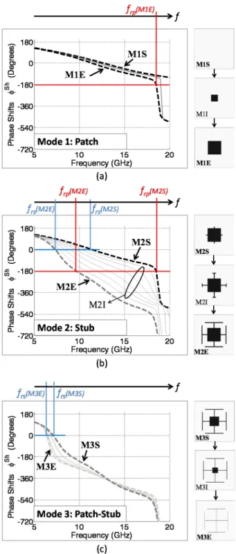
As depicted in Fig. 3.a, at the start of mode 1 (i.e. M1S), there is no resonance in the frequency range [5-20] GHz. When the patch is added, a patch resonance appears at a frequency frp. This frequency decreases when Lp increases until it reaches frp(M1E) 18.5GHz at the end of mode 1.
In mode 2, the cell incorporates a patch and a stub. With the increase of the stub length, the stub resonance appears at a frequency frs. Obviously, as illustrated in Fig. 3.b, the
resonant frequency frs decreases from frs(M2S) 11.5GHz till frs(M2E) 7GHz when the length of the stub increases. Simultaneously, as it is connected to the patch, the stub also affects the resonant frequency of this one which then decreases till frp(M2E) 10GHz with the increase of stub’s length. As a consequence, linear and parallel phase responses with respect to frequency are obtained in vicinity to the central frequency f0 = 12.5GHz.
Finally, in mode 3 (cf. Fig. 3.c), the stub resonant frequency continues to decrease as its physical length increases due to the reduction of the patch size as well as the decrease of its width. At the end of mode 3, it reaches
frs(M3E) 6.5GHz. On the other hand, as the decrease in size of the patch is compensated by an increase of the stub connected to it, one can conclude that changes in the phase response in this mode are mainly due to the resonance of the stub.
C. Phase Responses and Bandwidth
The phase responses of the suggested cell in all modes are combined in Fig. 4. In this figure, dashed curves represent the start/end of a mode (i.e. MαS/MαE) and the continuous lines represent intermediate states (i.e. MαI). As can be noticed, a phase range of 360˚ is achieved at the central frequency. The phase ranges covered by each of the
three modes of operation at the central frequency f0 are summarized in Table I. Although a 292˚ phase range is covered by Mode 2 solely, we note that Modes 1 and 3 are required to complete the remaining 68˚ from one side and provide the rebirth capability for the cell from the other side.
Furthermore, within a frequency band ranging from 10 to 15GHz, all phase responses are quasi-linear. The maximum phase dispersion is obtained at the transition from mode 2 to mode 3 and is equivalent to 55˚/GHz whereas the smallest one is obtained at the beginning of mode one and is equivalent to 21˚/GHz. As such, the difference between the smallest and the highest phase dispersion is maintained less than 34˚/GHz within a 40% bandwidth. Compared to cells in [4], [5] the cell we suggest here performs better in terms of maximum dispersion and phase range at f0, whereas compared to cells in [1], [3], it is characterized by a higher bandwidth.
III. EFFECTS OF INCIDENCE ANGLES
A. Phase Errors at the Central Frequency
The cell’s phase responses are now investigated under different angles of incidence. To do so, the previously defined boundary conditions are changed to master/slave conditions and a Floquet port is used instead of a traditional wave port. Thus, the cell is always supposed to be placed in an infinite array of identical elements but under different angles of incident wave θinc. All simulations are carried out in HFSS commercial software.
Fig. 5 groups the simulated phases at the central frequency f0 = 12.5GHz for selected cell configurations in mode 1, 2 and 3 and for θinc = 0˚, θinc = 30˚ and 45˚. As can be seen, the cell behaves quite well under incidence angles below 30˚ (i.e. θinc ≤ 30˚) as the phase error remains below 17˚ in all modes and for all the cell’s configurations. Even for higher incident angles of up to 45˚ (i.e. θinc ≤ 45˚) the phase error remains under 30˚ within a phase range of 292˚ (which is covered by mode 2) and reaches 38˚ within the remaining phase range (which is covered by mode 1 and 3).
Fig. 5. Patch-Stub Phoenix cell: effects of incidence angles at the central frequency (at f0=12.5GHz).
Fig. 4. Patch-Stub Phoenix cell under normal incidence: simulated phase responses versus frequency.
TABLE I. PHASE RANGE AT THE CENTRAL FREQUENCY Phases at f0 = 12.5GHz Phase Range at
f0 = 12.5GHz # Mode from to 1 Patch 5˚ -26˚ 31˚ 2 Stub -26˚ -318˚ 292˚ 3 Patch-Stub -318˚ -355˚ 37˚ All All 5˚ -355˚ 360˚ 5 10 15 20 -720 -540 -360 -180 0 180 Frequency (GHz) P h as e S h if ts φ Sh (D e g rees ) 10 10.5 11 11.5 12 12.5 13 13.5 14 14.5 15 -450 -400 -350 -300 -250 -200 -150 -100 -50 0 50 Frequency (GHz) Phas e Shif ts φ Sh (D eg rees ) Mode 1: Patch Mode 2: Stub Mode 3: Patch-Stub 360˚ phase range Mode 1: Patch Mode 2: Stub Mode 3: Patch-Stub
B. Effects on Phase Responses and Bandwidth
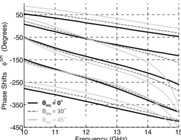
Fig. 6 shows the phase responses of a set of cell’s configurations (configurations 1, 4, 6, 8, 10 of Fig. 5) when θinc takes the values θinc = 0˚, θinc = 30˚ and 45˚. As can be noticed, the linearity and phase dispersion of these phase curves are almost the same for incidence angles below 30˚ (i.e. θinc ≤ 30˚). Same conclusion is extracted from Fig. 6 for higher incident angles of up to 45˚ (i.e. θinc ≤ 45˚) but within a reduced frequency band ranging from 10 to 14GHz. Indeed, for incidence angles above 30˚, the cell becomes more dispersive around 15GHz which affects the phase dispersion in the range 14-15GHz.
As a conclusion, accounting for incidence angles of up to 30˚ the suggested cell retains phase dispersion less than 34˚/GHz within a 40% bandwidth. Accounting for higher incidence angles of up to 45˚ the suggested cell retains the same phase dispersion but within a reduced bandwidth of 32%.
IV. CONCLUSION
In this paper, a novel Phoenix cell for large band reflectarray antennas is suggested. As a Phoenix cell, it is characterized by a rebirth capability allowing for reflectarray layouts with no abrupt variations and thus improved gain curves. In addition, unlike its predecessors, it involves three modes of operation, a patch, a stub and a combined patch– stub mode. As a consequence, a full 360˚ phase range at the central frequency is obtained as well as linear and parallel phase responses within a large frequency band. The obtained phase dispersion is maintained less than 34˚/GHz within a bandwidth of 40% and for incidence angles of up to 30˚. Furthermore, for higher incident angles of up to 45˚, the cell is capable of retaining the same phase dispersion behavior within a 32% bandwidth.
ACKNOWLEDGMENT
The authors would like to thank the Australian College of Kuwait for partially funding the research work presented in this paper.
V. REFERENCES
[1] L. Mustafa, R. Gillard, F. Peris, R. Loison, H. Legay, E. Girard, “The Phoenix cell: a new reflectarray cell with large bandwidth and rebirth capabilities,” IEEE Antennas and wireless propagation letters, vol. 10, pp. 71-74, 2011.
[2] M.-A. Milon, R. Gillard, H. Legay, “Rigorous analysis of the reflectarray radiating elements: Characterization of the specular reflection effect and the mutual coupling effect,” in Proc. of the 29th ESA Workshop on Multiple Beams and Reconfigurable Antennas, pp. 39-42, 2007.
[3] R. Deng, F. Yang, S. Xu, and M. Li, “A low-cost metal-only reflectarray using modified slot-type Phoenix element with 360˚ phase coverage”, IEEE Transactions on antennas and propagation, vol. 64, no. 4, pp. 1556-1560, 2016.
[4] T. Makdissy, R. Gillard, E. Fourn, E. Girard, H. Legay, “A patch-slot combination approach for large band reflectarrays,” in IEEE European Microwave Conference, pp. 759-762, 2012.
[5] H. Salti, R. Gillard, “Slot-Patch Cell with Low Phase Distortion for Large Band Reflectarrays”, in Proc. of the Fifth International Conference on Digital Information and Communication Technology and its Applications, pp. 187-189, 2015.
[6] R. Florencio, J. A. Encinar, R. R. Boix, V. Losada, G. Toso, “Reflectarray Antennas for Dual Polarization and Broadband Telecom Satellite Applications”, IEEE Transactions on antennas and propagation, vol. 63, no. 4, pp. 1234 - 1246, 2015.
[7] E. Carrasco, J.A. Encinar, M. Barba, “Bandwidth Improvement in Large Reflectarrays by Using True-Time Delay,” IEEE Transactions on antennas and propagation, vol. 56, no. 8, pp. 2496 - 2503, 2008. [8] Fei Xue, Hong-Jian Wang, Min Yi, Guang Liu, Xing-chao Dong,
“Design of a broadband single-layer linearly polarized reflectarray using four-arm spiral elements,” IEEE Antennas and wireless propagation letters, in press.
[9] M. Rafaei-Booket, Z. Atlasbaf, M. Shahabadi, “Broadband reflectarray antenna on a periodically perforated substrate,” IEEE Transactions on antennas and propagation, vol. 64, no. 8, pp. 3711-3717, 2016.
Fig. 6. Patch-Stub Phoenix cell: effects of incidence angles on phase responses versus frequency.
10 11 12 13 14 15 -450 -350 -250 -150 -50 50 Frequency (GHz) P has e S h if ts φ Sh ( D egr ees ) θinc= 0˚ θinc= 30˚ θinc= 45˚