Open Research Online
The Open University’s repository of research publications
and other research outputs
Tracking a table tennis ball for umpiring purposes
using a multi-agent system
Conference Item
How to cite:
Myint, Hnin; Wong, Patrick; Dooley, Laurence and Hopgood, Adrian (2016).
Tracking a table tennis
ball for umpiring purposes using a multi-agent system.
In: The 20th International Conference on Image
Processing, Computer Vision, & Pattern Recognition, 25th - 28th July 2016, Las Vegas, USA.
For guidance on citations see FAQs.
c
[not recorded]
Version: Accepted Manuscript
Copyright and Moral Rights for the articles on this site are retained by the individual authors and/or other
copyright owners. For more information on Open Research Online’s data policy on reuse of materials please
consult the policies page.
TRACKING A TABLE TENNIS BALL FOR UMPIRING PURPOSES USING A
MULTI-AGENT SYSTEM
Hnin Myint, Patrick Wong, Laurence Dooley
The Open University
United Kingdom
{hnin.myint, patrick.wong,
Laurence.Dooley}@open.ac.uk
Adrian Hopgood
HEC Liege – Management School
University of Liege
Belgium
[email protected]
ABSTRACT
Tracking a table tennis ball for umpiring purposes is a challenging task as, in real-match scenarios, the ball travels fast and can become occluded or merged with other background objects. This paper presents the design of a multi-view based tracking system that can overcome the challenges of tracking a ball in real match sequences. The system has been tested on a complete table tennis rally and the results are very promising. The system is able to continuously track the ball with only marginal variations in detection. Furthermore, the initialization of the multi-camera system means it is both a portable and cost-effective solution for umpiring purposes.
Index Terms— object detection, tracking, view,
multi-agent system, table tennis
Regular Research Paper – Computer Vision Application 1. INTRODUCTION
Table tennis is a popular Olympic sport with millions of regular players and tournaments held worldwide. In tournaments, one important task is to umpire the matches accurately. Umpiring a table tennis match is challenging even for professionally trained practitioners as many observations are required within a very short period of time. For example, during the service part of a rally, 31 observations are required within a second [1]. Furthermore, some of the observations and judgements described by the table tennis rules are very difficult for humans to make, such as to whether the ball touches the net, hits the edge of the table or exceeds the minimum height allowed during services. To this end, a purpose-built computer vision system that is able to evaluate and assist in identifying these difficult observations provides the motivation for this work. One important activity of such a system is to accurately and rapidly track the location of the ball during a match. While the ultimate objective is to develop an automatic umpiring system, the focus in this paper is upon the design of this purposed-built ball tracking system. In order for an automatic umpiring system to be widely
applied, it needs to be portable, inexpensive, and able to accurately track in real-time objects such as a table tennis ball in real match scenes.
The remainder of the paper is organized as follows: Section 2 reviews the literature relating to tracking table tennis balls, while Section 3 describes the proposed multi-view ball detection and tracking framework. Section 4 presents the experimental set up, results and discussion, while Section 5 makes some concluding comments.
2. LITERATURE REVIEW
Although many publications related to object tracking are available, the techniques that produce satisfactory results are usually object and application specific [1]. Thus the survey of literature for this paper will focus on tracking a table tennis ball. Two previous solutions for ball tracking for umpiring purposes have been proposed [1] and [2], while the other relevant methods [4-7] have tended to involve playing robots rather than real matches. A two-pass color thresholding (CT) technique is proposed by [1] to identify the ball from a real match scene. While satisfactory results were achieved, it only covered the service part of the rallies during which the ball is not traveling at very high speed. In contrast, the automated scoring system in [2] tracks the table tennis ball in real time and relates to the table and net to determine when a point is scored. However, the setting is based on a laboratory environment with the ball painted a special neon green against a uniformly black background. Such a prescribed environment significantly reduces the ball detection challenge, and so this is unacceptable for formal tournaments, as the Laws of Table Tennis mandate the color of ball can only be matt white or orange [3]. The growth of sampled points method was proposed by [4], which aims to recover pixels unintentionally lost during the adjacent frame differencing. Although experimental results reveal promising ball detection performance, background pixels can be incorrectly classified as belonging to the ball, which degrades the overall detection accuracy. On the other hand, [5] attempted to improve the tracking performance by employing an iterative dynamic window tracking method. Despite the
system being able to track the ball reasonably well, the computational complexity involved mitigated against real-time operation. An alternative approach to the ball tracking, involved a multi-view scheme with an aerodynamic model of the ball’s three dimensional (3D) flight path [6] and [7]. It was further improved in [7] with an additional bouncing model, which takes into consideration the bouncing characteristic of the ball. While some degree of improvement in the tracking of a table tennis ball is achieved, the test video sequences used comprised relatively simple backgrounds, which does not resemble a real match scene, where the view can become obstructed by the players against complex backgrounds where ball merging can occur. Moreover, in the dual-camera based 3D trajectory reconstruction algorithm, it is critical that both cameras detect the ball at the same time in order to calculate the 3D position of the ball. This restriction means that the 3D position of the ball cannot be determined when one of the cameras fails to detect the ball. In addition, a vision system using multiple cameras must simultaneously process frames from different views, thus incurring a heavy workload which impacts on the system’s performance.
In summary, no existing literature addresses the challenges of tracking the ball in a full real match rally, which is an essential requirement for a realistic automatic umpiring system. Furthermore, the success of current solutions heavily relies on the availability of aerial views of the scene, which renders the ball against a relatively simple background i.e., a uniform colored table and floor [4]-[7]. Obtaining aerial views is not always possible as most table tennis tournaments take place at multi-purpose sport venues and fixing cameras to the ceiling or high wall is not allowed. This paper thus proposes a novel and portable multi-view ball tracking system which is designed to manage challenging ball detection situations in real match scenes.
3. Multi-View Ball Tracking Framework
To umpire a match automatically, one basic requirement is to track the ball’s real world 3D position and use it to compare with the positions of other objects such as the table and net. The main difficulties of tracking the ball in a match scene are that the view of the ball can be occluded, merged with objects in the background, its trajectory can change suddenly as it is struck and it travels fast. Six example frames reflecting these challenging detection situations are shown in Figure 1. One approach to overcome occlusion is to employ a multi-view system which monitors the ball at different angles. This approach also enables the derivation of the ball’s 3D position. However, this requires a high degree of inter-view co-ordination as well as the ability to resolve conflicts when inconsistent information is received.
Ball blurry Ball reflection
Color merging Complex background
Multiple moving objects (ball and hand)
Multiple moving objects (ball and spectators) Figure 1. Ball Detection challenging scenarios To tackle this problem, a purposed-built Multi-Agent System (MAS) is proposed. A MAS consists of a number of inter-connected intelligent agents, which can either independently or jointly achieve goals. The main strengths of a MAS are: i) agents with various specialist knowledge can work together to complete complicated tasks; ii) it is a distributed structure that facilitates shared workloads via a network of computers; and iii) it is a modular design so the system is scalable [8]. This makes a MAS an ideal platform for the multi-view ball tracking application, where each camera can be controlled by ball detection agents, which possess the specialist knowledge in detecting balls from their views independently. Another agent can play the role of a coordinator controlling the flow of the information between the ball detection agents and resolve conflicts if conflicting information from different agents is received. The agents can also be run on a network of computers and this can enhance the system performance, especially if real-time tracking is required. When more cameras are needed by the tracking system, the system can be scaled up by simply adding more ball detection agents. Another important benefit is that the MAS software manages the networking and communication aspects of the system, so users do have to deal with these aspects. Furthermore, MASs
have also been applied in other object tracking applications [9] and [10]. More details of the proposed MAS based ball tracking system are given in Section 3.1.
In terms of the color merging problem, a combined CT and motion-based background subtraction (BS) approach is adopted to segment the ball from the background. It dynamically adapts the color thresholds and jointly uses the CT and BS information to segment difficult objects [11]. To tackle sudden changes of trajectory, the proposed approach captures frames at 300 frames per second (fps). At this rate, the motion vector of the ball between two successive frames is relatively small and a simple second-order motion model can be used to model the trajectory. This approach also helps capture the fast traveling ball more clearly.
3.1. Camera Configuration and MAS Architecture
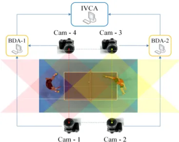
Although capturing the image of an object from multiple angles can increase the probability of detection, consideration has to be given to the design configuration of the multi-view system, i.e., how many cameras are employed, where each camera is placed and how they are paired with another camera to derive the 3D position of the object. To achieve a pragmatic balance between detection accuracy and cost, four cameras were used at the positions shown in Figure 2. They jointly track the ball spatially within an area comprising the table and players. Each camera covers approximately two thirds of the length of the table, but from different perspectives. In this arrangement, the main playing area is thus covered by four cameras, with the coverage overlapping around the net area, where particular attention is needed for umpiring. As each individual camera does not have to cover the entire table, the cameras can be placed closer to the objects of interest (e.g. ball and table) so that better depth resolution is achieved when deriving their 3D positions and the objects appear bigger in the views. The 3D positions of the objects can also be derived from either the opposite facing pairs or the side-by-side pairs using triangulation and geometry calculations. A limitation of this configuration is that when the position of the ball is at or near the vertical plane joining the principal points of the opposite facing cameras (see red and yellow dotted lines in Figure 2), the 3D positions cannot be determined using triangulation because the angle between the ball and the two cameras is zero. The position of the ball in these situations is thus extrapolated using a second-order equation of motion (SOEM) to model the trajectory of the table tennis ball during a rally.
Figure 2. Multi-view camera setup
As shown in Figure 2, each opposite facing camera pair is connected to a Ball Detection Agent (BDA), which detects the two-dimensional (2D) position of the ball from each view. From this, the 3D real world position of the ball is derived and sent to the Inter-View Correction Agent (IVCA) for storage. IVCA checks the consistency of the ball’s 3D position from multiple BDAs and uses this information to estimate the ball position. If a particular view gives an incorrect ball location, the corrected screen position of the ball is sent to the relevant BDA managing that view, for correction. As each BDA only monitors a portion of the table, the IVCA selectively instructs which BDA to report the ball position and which to hibernate. The IVCA then sends the 3D ball position to other agents (not shown in Figure 2 for clarity) for an umpiring decision.
The ball detection process employed by BDA uses a modified
Combined Adaptive Color Thresholding and Motion Detection (MACTMD) algorithm [11], which exhibits robust
ball detection but only in a conventional adjacent camera arrangement. Modifications have been introduced so the ball’s 3D position can be derived from opposite-facing cameras. Also since ACTMD was written in C++ while the MAS framework employed is written in Java, a pipe based inter-process communication module was developed to bridge the employed MAS and modified ACTMD.
Figure 3 shows the connections and information flows between the MAS modules. At initialization, the IVCA instructs BDAs to report the ball position. If the ball is visible, the ball position is returned, otherwise the BDA states a “no ball” and is hibernated. BDAs obtain the ball position through a pipe connection to the MACTMD, which detects the ball from video signals from opposite-facing cameras. The process continues until the ball is detected in the overlapped
zone where it is visible by both camera pairs (area near the middle of the table in Figure 2), at which time the IVCA will instruct the relevant BDA to wake up and report the ball position. When the ball eventually disappears from the view of the BDA which initially observed the ball, the IVCA instructs it to hibernate. This process continues until the end of the rally.
Figure 3. Architecture of the MAS
3.2. Compensating measuring errors
While the proposed camera configuration can provide robust ball detection, experimental results confirm that camera alignment is very challenging and time consuming. Any misalignment could cause measurement errors in the 3D position of the detected ball, thereby impacting upon the accuracy of the overall umpiring system. For this reason, an error model was developed to compensate for these errors, which are represented by 3-D vectors. Empirical analysis showed that the measurement error exhibited a non-linear relationship to the ball location, so quadratic surfaces were chosen for the error modelling, with data being fitted to surfaces using a standard Multivariate Polynomial Regression [12]. The error model equations are given in (1), where E(x, y, z) is the 3-D error vector, F(x,y,z), G(x,y,z), H(x,y,z)
are functions determining the magnitudes of the i, j, k components respectively, and (x, y, z) is the measuring ball location.
E(x, y, z) = F(x,y,z)i, G(x,y,z)j, H(x,y,z)k ………..…… (1) Thus the error model takes the 3D ball location as input and produces an error vector for that particular location.
Equations (2), (3) and (4) define the quadratic surfaces of
F(x,y,z), G(x,y,z), H(x,y,z) respectively,where an, bn, cn, dn, en,
fn, gn, hn, in and jn are coefficients of the surfaces, for n = 1, 2
and 3.
F(x,y,z)=a1x2+b1y2+c1z2+d1xy+e1xz+f1yz+g1x+h1y+i1z+j1 …..(2)
G(x,y,z)=a2x2+b2y2+c2z2+d2xy+e2xz+f2yz+g2x+h2y+i2z+j2 …..(3)
H(x,y,z)=a3x2+b3y2+c3z2+d3xy+e3xz+f3yz+g3x+h3y+i3z+j3 …..(4)
For calibration purposes, a checker board which has 4 rows and 5 columns of identical sized black squares distributed evenly upon a white board, was employed. It was carefully placed at various known positions during sequence filming as shown in Figure 4. As the position of each square corner on the checkerboard can be easily calculated, this provided a rich set of reference points for training the error model.
Figure 4 A double-sided checker board used for calibration To prevent overfitting, a small subset of 32 points were randomly selected from some known positions on the checker board as training data and 45 “unseen” points were chosen for testing. Figure 5(a) shows the 45 uncompensated calculated (red) and expected (blue) ball locations, while Figure 5(b) shows the corrected ball locations after error compensation. It is evident the calculated and expected positions are much closer, with the average Euclidean distance between them being reduced from 4.8cm to only 0.1cm.
(b) Compensated ball positions
Figure 5. Expected and calculated 3D position of the ball
4. EXPERIMENTAL SETUP AND RESULTS
The MAS has been developed using a Java Agent DEvelopment Framework (JADE) [13], which is open-source and platform independent. It complies with the de-facto standard set by Foundation for Intelligent Physical Agents. The proposed system can be distributed across a network of computers and agents can be migrated from one machine to another if required. All experiments were conducted on a computer with an Intel® Core™ i7 CPU @ 2.80 GHz with the detecting and tracking algorithms implemented in C++ employing OpenCV [14].
To test the system, a 4-view match scene sequence was captured, consisting of 450 frames per view, with spatial resolution of 512×384 pixels and a capture rate 300 frames per second (fps). Both resolution and frame rates were limited by the entry-level high speed camera hardware. The sequence was of duration 1.5 seconds and consisted of a complete table tennis rally which included challenging ball detection conditions such as sudden changes in trajectory, occlusion, uneven illumination, multiple object motion and camera noise. The video is available at the Open University Table Tennis video database [15]. Furthermore, due to the high capturing rate and shutter speed, the video is of low contrast. Cyclic variations in illumination is also evident due to the higher capturing rate than the standard 50Hz used by the lights. As it is a complete rally, it consists of a service, ball traveling back and forth between the table and striking by the players, and an eventual foul. A summary of the characteristics of the test sequence is shown in Table 1. To evaluate the detection performance of the system, the detected 2D ball locations are reprojected to the 3D space and compared with the 3D reprojected ball locations identified by human volunteers.
Table 1 Characteristics of the test sequence No. of view 4
No of frames per view 450 (for one complete rally) Size of frame (pixels) 512×384
Capture rate 300 fps Ball radius 4 pixels Ball colour White Key detection
Challenges
Complex background, color merging, ball reflection, multiple moving objects, occlusion, very small ball size To establish a ground truth for detection, the set of ball locations were manually identified in each frame of each view (a total of 1800 locations) and then mapped into 3D space. As this is a very time consuming process, only one test sequence was produced, though this sequence does contain all the key events of a typical table tennis rally. An example frame from this sequence is shown in Figure 6, where the red circle indicates the detected ball position while the green square defines the region of interest (ROI) within which object detection takes place. Figure 7 shows the corresponding views for all four cameras and the detection results in the sample frame, with the ball clearly visible and successfully detected by all four cameras.
Figure 6. Ball detected against a very similar color background
(a) 3D ball trajectory from the server to receiver
(b) 3D ball trajectory from the receiver to server Labels:
1: Start of the service at Frame #1,
2: The ball bounces on the server side of the table 3: The ball crosses over the net
4: The ball bounces on the receiver side of the table 5: The ball is stroke by the receiver
6: The ball bounces on the server side of the table 7: The rally ends.
Figure 8. Trajectory comparison between the ground truth and the detected ball locations
Figure 8 shows the result comparison between the ground truth (red) and the detected ball locations (blue). The two trajectories almost overlap, indicating good ball detection accuracy, including crucially some of the detection challenges identified earlier. In particular, the system satisfactorily resolves problems like color merging and occlusion, by consistently detecting the ball. Figure 6 shows an example of these successful detections when the color of the background object (white) is very similar to the ball (color merging), while Figure 9 shows a successful detection when the ball is partially occluded in one of the views.
(a) The ball is partially occluded by the player’s bat
(b) The ball is visible and detected by the corresponding opposite facing camera.
Figure 9 Examples of occlusion. The occluded ball is recovered using the inter-view correction method.
However, some errors do occur, especially in regions where the position of the ball is near the plane that joins the principal points of the opposite facing cameras. This means the ball positions estimated by the SOEM can be inaccurate when there are too much noise in the ball trajectory. Nevertheless, successful detections resume shortly after the ball passes that region.
The average Euclidean distance between the detected ball location and ground truth is 3 cm if the ball locations in the region near the plane that joins the principal points of the opposite facing cameras are omitted, otherwise it is 11 cm. The accuracy of umpiring is most important near the net or table edge, where the detection errors are relatively low. The time taken to detect the ball in a frame is 2.8ms. However, if 4 BDA and an IVCA are employed instead and each agent runs on a separate computer, this time can be
reduced to around 0.56ms. This means the full 450 frame test sequence (1.5 seconds) can be processed within 2.52 seconds. The time lag is only 1.02 seconds, which is an acceptable window for making an accurate umpiring decision.
5. CONCLUSION
This paper has presented a MAS-based ball tracking system, which is designed to be low-cost, portable and for umpiring purposes. A multi-view camera configuration was designed such that a minimum number of cameras were required yet it was able to cover a large area and provide enough video clarity for tackling the detection challenges. Furthermore, a measurement error correction model was derived and the model significantly reduced the detection errors. With no need to fix a camera to the ceiling, the system is portable, which is very important as most table tennis tournaments take place at multi-purpose sport venues where installation of fixed equipment is not permissible.
The ball tracking system has been tested on a complete rally sequence from a real match scene and the result is very promising. The detected ball locations are very similar to the ground truth. Although detection errors occur sometimes, the system is able to recover and resume successful detections. The errors could be reduced with a more accurate extrapolation model.
The agent-based design allows parallel computation and scalability. Although a single computer was used in these trials, individual agents can run on separate computers, thereby enabling real-time tracking. More cameras (and agents) can be added to the system without significantly changing the program or its performance.
6. REFERENCES
[1] K. C. P. Wong and L. S. Dooley, ‘High-motion table tennis ball tracking for umpiring applications’, in 2010 IEEE 10th
International Conference on Signal Processing (ICSP), 2010,
pp. 2460–2463.
[2] G. Byrd, ‘21st Century Pong’, IEEE, vol. 48, no. 10, pp. 80– 84, Oct. 2015.
[3] "Law of Table Tennis", International Table Tennis Federation Handbook, [Online]. Available:
http://www.ittf.com/ittf_handbook/hb.asp?s_number=2 [Accessed: 22-Mar-2016].
[4] Z. Zhang, D. Xu, and M. Tan, ‘Visual Measurement and Prediction of Ball Trajectory for Table Tennis Robot’, IEEE
Trans. Instrum. Meas., vol. 59, no. 12, pp. 3195 –3205, Dec.
2010.
[5] J. Liu, Z. Fang, K. Zhang, and M. Tan, ‘Improved high-speed vision system for table tennis robot’, in 2014 IEEE
International Conference on Mechatronics and Automation (ICMA), 2014, pp. 652–657.
[6] X. Chen, Q. Huang, W. Zhang, Z. Yu, R. Li, and P. Lv, ‘Ping-pong trajectory perception and prediction by a PC based High speed four-camera vision system’, in 2011 9th
World Congress on Intelligent Control and Automation (WCICA), 2011, pp. 1087 –1092.
[7] H. Bao, X. Chen, Z. Wang, M. Pan, and F. Meng, ‘Bouncing model for the table tennis trajectory prediction and the strategy of hitting the ball’, in 2012 International Conference
on Mechatronics and Automation (ICMA), 2012, pp. 2002 –
2006.
[8] A.A. Hopgood, 'Intelligent Systems for Engineers and Scientists', 3rd edition, CRC Press, (2012), ISBN 9781439821206.
[9] M. Chakroun, A. Wali, and A. M. Alimi, ‘Multi-agent system for moving object segmentation and tracking’, in 2011 8th
IEEE International Conference on Advanced Video and Signal-Based Surveillance (AVSS), 2011, pp. 424 –429.
[10] Y. Li, Y. Wang, Y. Qi, and H. Li, ‘Multi-agent based particle filter for moving object tracking’, in 2010 International
Conference on Computer Application and System Modeling (ICCASM), 2010, vol. 4, pp. V4–124 –V4–128.
[11] H. Myint, P. Wong, L. Dooley, and A. Hopgood, ‘Tracking a table tennis ball for umpiring purposes’, in 2015 14th IAPR
International Conference on Machine Vision Applications (MVA), 2015, pp. 170–173.
[12] Rawlings, J.O., Pantula, S.G. and Dickey, D.A. “Applied Regression Analysis: A Research Tool” Second Edition, Springer-Verlag, 1998
[13] ‘JAVA Agent DEvelopment Framework’. [Online]. Available: http://jade.tilab.com/ [Accessed: 22-Mar-2016] [14] ‘Open Source Computer Vision Library’. [Online]. Available:
http://opencv.org/. [Accessed: 22-Mar-2016].
[15] ‘The Open University table tennis video database’. [Online]. Available: http://users.mct.open.ac.uk/xgmt/outtdb/. [Accessed: 22-Mar-2016].

![Figure 5. Expected and calculated 3D position of the ball 4. EXPERIMENTAL SETUP AND RESULTS The MAS has been developed using a Java Agent DEvelopment Framework (JADE) [13], which is open-source and platform independent](https://thumb-eu.123doks.com/thumbv2/123doknet/5842330.141629/6.892.460.813.214.390/expected-calculated-experimental-results-developed-development-framework-independent.webp)

