Engineered Zeolitic Materials:
Synthesis and Application
Thèse
Nima Masoumifard
Doctorat en génie chimique
Philosophiae Doctor (Ph.D.)
Québec, Canada
Engineered Zeolitic Materials:
Synthesis and Application
Thèse
Nima Masoumifard
Sous la direction de :
Freddy Kleitz, directeur de recherche
Serge Kaliaguine, codirecteur de recherche
iii
Résumé
Les zéolithes étant des matériaux cristallins microporeux ont démontré leurs potentiels et leur polyvalence dans un nombre très important d'applications. Les propriétés uniques des zéolithes ont poussé les chercheurs à leur trouver constamment de nouvelles utilités pour tirer le meilleur parti de ces matériaux extraordinaires. Modifier les caractéristiques des zéolithes classiques ou les combiner en synergie avec d'autres matériaux se trouvent être deux approches viables pour trouver encore de nouvelles applications. Dans ce travail de doctorat, ces deux approches ont été utilisées séparément, premièrement avec la modification morphologique de la ZSM-12 et deuxièmement lors de la formation des matériaux de type cœur/coquille (silice mésoporeuses@silicalite-1). La ZSM-12 est une zéolithe à haute teneur en silice qui a récemment attiré beaucoup l’attention par ses performances supérieures dans les domaines de l'adsorption et de la catalyse. Afin de synthétiser la ZSM-12 avec une pureté élevée et une morphologie contrôlée, la cristallisation de la zéolithe ZSM-12 a été étudiée en détail en fonction des différents réactifs chimiques disponibles (agent directeur de structure, types de silicium et source d'aluminium) et des paramètres réactionnels (l'alcalinité, ratio entre Na, Al et eau). Les résultats présentés dans cette étude ont montré que, contrairement à l’utilisation du structurant organique TEAOH, en utilisant un autre structurant, le MTEAOH, ainsi que le Al(o-i-Pr)3, cela a permis la formation de monocristaux ZSM-12 monodisperses dans un temps plus court. L’alcalinité et la teneur en Na jouent également des rôles déterminants lors de ces synthèses.
Les structures de types cœur/coquille avec une zéolithe polycristalline silicalite-1 en tant que coquille, entourant un cœur formé par une microsphère de silice mésoporeuse (tailles de particules de 1,5, 3 et 20-45 µm) ont été synthétisés soit sous forme pure ou chargée avec des espèces hôtes métalliques. Des techniques de nucléations de la zéolithe sur le noyau ont été utilisées pour faire croitre la coquille de façon fiable et arriver à former ces matériaux. C’est la qualité des produits finaux en termes de connectivité des réseaux poreux et d'intégrité de la coquille, qui permet d’obtenir une stéréosélectivité. Ceci a été étudié en faisant varier les paramètres de synthèse, par exemple, lors de prétraitements qui comprennent ; la modification de surface, la nucléation, la calcination et le nombre d’étapes secondaires de cristallisation hydrothermale. En fonction de la taille du noyau mésoporeux et des espèces hôtes incorporées, l'efficacité de la nucléation se révèle être influencée par la technique de modification de surface choisie. En effet, les microsphères de silice
iv
mésoporeuses contenant des espèces métalliques nécessitent un traitement supplémentaire de fonctionnalisation chimique sur leur surface externe avec des précurseurs tels que le (3-aminopropyl) triéthoxysilane (APTES), plutôt que d'utiliser une modification de surface avec des polymères ioniques. Nous avons également montré que, selon la taille du noyau, de deux à quatre traitements hydrothermaux rapides sont nécessaires pour envelopper totalement le noyau sans aucune agrégation et sans dissoudre le noyau.
De tels matériaux avec une enveloppe de tamis moléculaire cristallin peuvent être utilisés dans une grande variété d'applications, en particulier pour de l'adsorption et de la catalyse stéréo-sélective. Ce type de matériaux a été étudié lors d'une série d'expériences sur l’adsorption sélective du glycérol provenant de biodiesel brut avec des compositions différentes et à des températures différentes. Les résultats obtenus ont été comparés à ceux utilisant des adsorbants classiques comme par exemple du gel de sphères de silice mésoporeux, des zéolithes classiques, silicalite-1, Si-BEA et ZSM-5(H+), sous forment de cristaux, ainsi que le mélange physique de ces matériaux références, à savoir un mélange silicalite-1 et le gel de silice sphères. Bien que le gel de sphères de silice mésoporeux ait montré une capacité d'adsorption de glycérol un peu plus élevée, l'étude a révélé que les adsorbants mésoporeux ont tendance à piéger une quantité importante de molécules plus volumineuses, telles que les « fatty acid methyl ester » (FAME), dans leur vaste réseau de pores. Cependant, dans l’adsorbant à porosité hiérarchisée, la fine couche de zéolite silicalite-1 microporeuse joue un rôle de membrane empêchant la diffusion des molécules de FAME dans les mésopores composant le noyau/cœur de l’adsorbant composite, tandis que le volume des mésopores du noyau permet l’adsorption du glycérol sous forme de multicouches. Finalement, cette caractéristique du matériau cœur/coquille a sensiblement amélioré les performances en termes de rendement de purification et de capacité d'adsorption, par rapport à d'autres adsorbants classiques, y compris le gel de silice mésoporeuse et les zéolithes.
v
Abstract
Zeolites as microporous crystalline materials have shown competence and versatility in a huge number of applications. Their unique properties have persuaded researchers to constantly look for novel pathways to get the most out of these extraordinary substances. Modifying the properties of classical zeolites or combining them synergistically with other materials are found to be two viable techniques to attain efficient zeolitic materials with improved characteristics. In this dissertation, these two approaches were separately used to study, first, the morphological modification of ZSM-12 and second, the formation of mesoporous silica@silicalite-1 core-shell materials. ZSM-12 is a high silica zeolite which has recently attracted much attention owing to its superior performance in adsorption and catalysis. In order to synthesize ZSM-12 with high purity and controlled size and morphology, the crystallization behavior of ZSM-12 zeolite was thoroughly studied by screening different commercially available chemical sources (structure-directing agents, silicon and aluminum source types) and compositions (alkalinity and Na, Al and water contents). The results presented in this study showed that, in contrast to TEAOH organic template, using MTEAOH and Al(o-i-Pr)3 could lead to the formation of mono-sized ZSM-12 single crystals in a shorter time. Alkalinity and Na+ contents were found to be playing the major roles.
Following the second approach, zeolitic core-shell composites with a polycrystalline silicalite-1 shell, enclosing a mesoporous silica microsphere core (particle sizes of 1.5, 3 and 20-45 µm) in either pure form or loaded with metal guest species, were synthesized. Seeded growth technique was used as one of the reliable ways for the synthesis of such a material. The quality of the final products in terms of the pore network connectivity and shell integrity, which, together, ensure the shape-selective capability, was studied by varying synthesis parameters, such as core pre-treatments which include surface modification, seeding and calcination steps and the number of secondary hydrothermal crystallization steps. Depending on the core size and the presence of guest species, the quality of the seeding step was found to be influenced by the surface modification technique used, i.e., mesoporous silica microspheres which contain guest species need an additional treatment of chemical functionalization of the external surface with species such as APTES, rather than using a simple surface modification with ionic polymers. It was also shown that depending on the core size, two to four short hydrothermal treatments are required to fully cover the core, with no aggregation and core dissolution. Such materials with a molecular
vi
sieve crystalline shell can be used in a wide variety of applications, particularly for shape-selective adsorption and catalysis purposes.
Selective adsorption capability of the final product was investigated by conducting a series of batch glycerol adsorption experiments from crude biodiesel with different compositions at different temperatures. Glycerol content of the purified biodiesel by using the core@shell material was compared to those purified by using conventional adsorbents including bare mesoporous silica gel spheres, classical zeolites, e.g., silicalite-1, pure siliceous β-zeolite (Si-BEA) and ZSM-5(H+) crystals as well as a physical mixture of the constitutive materials, i.e., equally mixed silicalite-1 and silica gel spheres. Although mesoporous silica gel spheres showed slightly higher glycerol adsorption capacity, the study revealed that the mesoporous adsorbents tended to trap a significant number of bulkier molecules, such as FAMEs, in their large pore networks (dpore> 6 nm). However, the silicalite-1 shell provided a microporous membrane which hindered the diffusion of FAME into the mesopores while the composite adsorbents benefited from large pore volume of mesoporous silica as core compartment, allowing a multi-layer glycerol adsorption. This feature of the synthesized core@shell material considerably enhanced the dry washing performance in terms of purification yield and adsorption capacity, in comparison to other conventional adsorbents including mesoporous silica gel and classical zeolites.
vii
Table of Content
RÉSUMÉ ... III ABSTRACT ... V TABLE OF CONTENT ... VII LIST OF TABLES ... XII LIST OF FIGURES ... XIII LIST OF SCHEMES ... XX ABBREVIATIONS ... XXI ACKNOWLEDGMENTS ... XXIV FOREWORD ... XXV CHAPTER 1 - STATE-OF-THE-ART ... 1 1.1 Introduction... 1
1.2 Zeolites as Ordered Microporous Materials ... 1
1.2.1 Zeolite History ... 2
1.2.2 Zeolite Structure ... 3
1.2.3 Zeolite Classification ... 4
1.2.4 Zeolite Properties ... 5
1.2.5 Zeolite Synthesis ... 7
1.2.5.1 Formation Mechanism and Key Synthesis Elements ... 8
1.2.6 The Drawbacks of Classical Zeolites- Problem Description ... 11
1.3 Proposed Solutions ... 11
1.3.1 Large Pore Materials - Pros and Cons ... 12
1.3.2 Zeolitic Materials with Short Micropores ... 15
1.3.2.1 Nanozeolites- Pros and Cons ... 15
1.3.2.2 Hierarchical Zeolite - Pros and Cons ... 18
1.3.2.2.1 Hierarchical Zeolitic Structures - Synthesis Approaches ... 20
1.3.2.2.2 Macroscopic Structured Hierarchical Zeolites ... 25
1.3.2.3 Why Core@Shell and Hollow Zeolites? ... 27
1.4 Zeolitic Core@Shell Composites ... 28
viii
1.4.2 History ... 30
1.4.3 Zeolitic Core@Shell with Zeolite as Shell (Core@Zeolite)... 31
1.5 Synthesis of Core@Zeolite Materials ... 32
1.5.1 Zeolitic Coatings on Macroscopic Structures ... 32
1.5.1.1 Synthesis of Macroscopic Coated Zeolitic Structures ... 35
1.5.2 Synthesis of Zeolitic Core@Shell ... 37
1.5.2.1 Seeded Growth Technique ... 37
1.5.2.1.1 History ... 38
1.5.2.1.2 Notes on Synthesis Steps ... 44
1.5.2.1.3 Pros and Cons ... 45
1.5.2.2 In-Situ Technique ... 47
1.5.2.3 Physical Coating Technique ... 57
1.6. Synthesis of Hollow and Yolk-Shell Zeolitic Material ... 59
1.6.1 Templating Technique - Seeded Growth Technique ... 60
1.6.2 Post Treatment ... 63
1.6.2.1 Dissolution (Selective Desilication) ... 64
1.6.2.2 Dissolution-Recrystallization Technique ... 67 1.7 Applications ... 70 1.7.1 Adsorptive Separation ... 71 1.7.2 Catalysis ... 72 1.7.2.1 Shape Selectivity ... 72 1.7.2.2 Bi-functionality ... 74 1.7.2.3 Protecting Layer ... 74 1.7.2.4 Sintering Resistance ... 75
1.7.2.5 Passivation of External Surface Area ... 76
1.7.2.6 Easy Recovery ... 77
1.8 Organization of the Thesis ... 77
1.9 References ... 78
CHAPTER 2 - SYNERGY BETWEEN STRUCTURE DIRECTION AND ALKALINITY TOWARD FAST CRYSTALLIZATION, CONTROLLED MORPHOLOGY AND HIGH PHASE PURITY OF ZSM-12 ZEOLITE ... 90
ix Abstract ... 92 2.1 Introduction... 93 2.2 Experimental ... 97 2.2.1 Chemicals ... 97 2.2.2 Zeolite Preparation ... 97 2.2.2.1 Benchmark Syntheses ... 97 2.2.2.2 Proposed Synthesis: ... 98
2.2.2.2.1 TEA+ as Organic Template ... 98
2.2.2.2.2 MTEA+ as Organic Template ... 98
2.2.3 Characterization ... 99
2.3 Result and Discussion ... 101
2.3.1 TEA+ as Organic Template ... 101
2.3.1.1 Issues with the Use of TEA+- Why MTEA+? ... 108
2.3.2 MTEA+ as the Organic Template... 109
2.3.2.1 Using MTEAOH as Organic Template ... 110
2.3.2.1.1 Crystallization Time- Rapid Crystallization ... 115
2.3.2.1.2 Controlled Size and Morphology ... 116
2.3.2.2 Effect of Al Source ... 116
2.3.2.3 Effect of Water Content ... 117
2.3.2.4 Effect of Si Source ... 117 2.3.2.5 Effect of Al Content ... 117 2.3.2.5.1 Al-Rich ZSM-12 ... 117 2.3.2.5.2 Pure Silica ZSM-12 ... 123 2.4 Conclusions ... 127 2.5 Acknowledgement ... 128 2.6 Supporting Information ... 129 2.6.1 Experimental Section ... 129
2.6.1.1 MTEA+-Based ZSM-12 Benchmark ... 129
2.6.1.2 TEA+-Based ZSM-12 Benchmark ... 129
x
CHAPTER 3 - SYNTHESIS OF MICROPOROUS/MESOPOROUS CORE-SHELL MATERIALS WITH CRYSTALLINE ZEOLITIC SHELL AND SUPPORTED METAL
OXIDE SILICA CORE ... 142
Résumé ... 143
Abstract ... 144
3.1 Introduction... 145
3.2 Experimental ... 147
3.2.1 Pure Mesoporous Silica@Silicalite-1 Preparation ... 147
3.2.2 Preparation of Metal-Containing Mesoporous Silica Microspheres ... 148
3.2.3 Preparation of Supported Metal Oxide Mesoporous Silica@Silicalite-1 ... 149
3.2.4 Materials Characterization ... 150
3.3 Results and Discussion ... 151
3.3.1 Effect of Secondary Growth Repetitions Using Pure Silica Cores ... 152
3.3.2 Effect of Surface Modifications Using Metal-Containing Cores ... 157
3.4 Conclusion ... 167
3.5 Acknowledgements ... 167
3.6 Supporting Information ... 168
3.7 References ... 179
CHAPTER 4 - ZEOLITIC CORE@SHELL ADSORBENTS FOR THE SELECTIVE REMOVAL OF FREE GLYCEROL FROM CRUDE BIODIESEL ... 181
Résumé ... 182
Abstract ... 183
4.1 Introduction... 184
4.2 Experimental Section ... 187
4.2.1 Preparation of Biodiesel ... 187
4.2.2 Synthesis of the Core@Shell Adsorbents ... 187
4.2.2.1 Preparation of Silicalite-1 Nanocrystals ... 188
4.2.2.2 Preparation of Core Materials ... 188
4.2.2.3 Preparation of Core@Shell Products ... 189
4.2.3 Material Characterization ... 190
4.2.4 Glycerol Adsorption Test ... 190
xi
4.3 Results and Discussion ... 193
4.3.1 Synthesis and Characterization of the Sorbents ... 193
4.3.2 Purification of Crude Biodiesel ... 205
4.3.2.1 Glycerol Adsorption from Methanol-Free Biodiesel ... 206
4.3.2.2 Glycerol Adsorption from Methanol-Free Biodiesel at Elevated Temperatures ... 212
4.3.2.3 Glycerol Adsorption from Methanol-Containing Biodiesel ... 214
4.3.2.4 Glycerol Adsorption from Methanol-Containing Biodiesel at Elevated Temperature .. 216
4.4 Conclusions ... 219
4.5 Acknowledgements ... 219
4.6 Supporting Information ... 220
4.7 References ... 229
CHAPTER 5 - GENERAL CONCLUSIONS AND PERSPECTIVES ... 232
5.1 Future Work ... 235
APPENDIX - HEXAGONAL MESOPOROUS SILICA SPHERES (HMS) ... 237
Morphology Control ... 238
Optimized Synthesis Method ... 239
xii
List of Tables
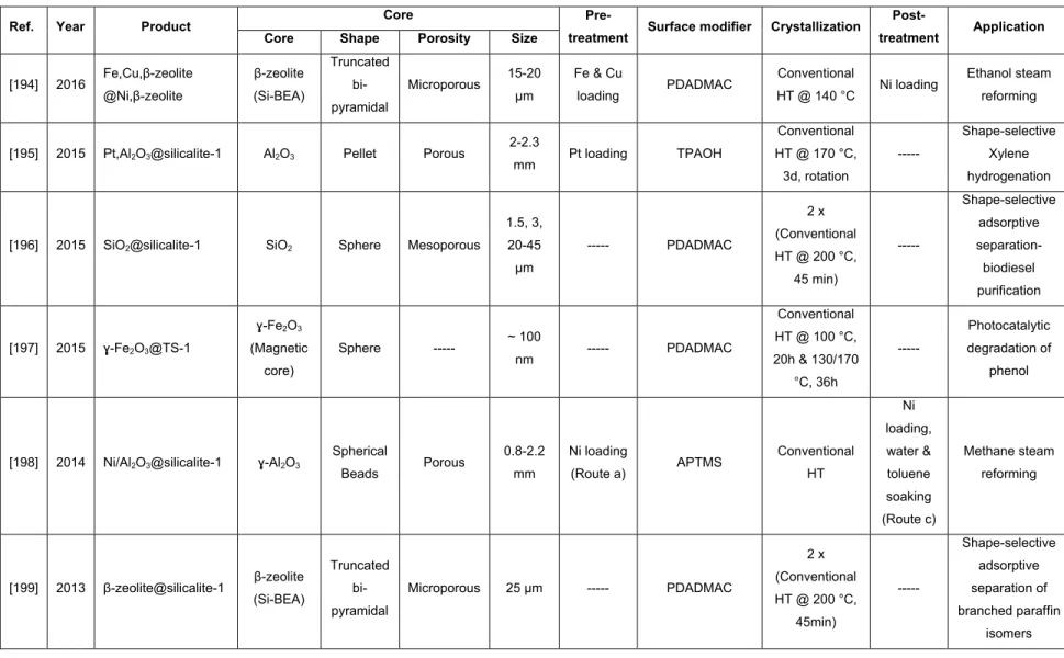
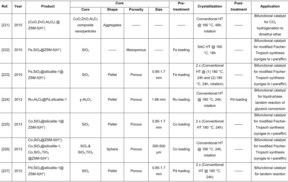
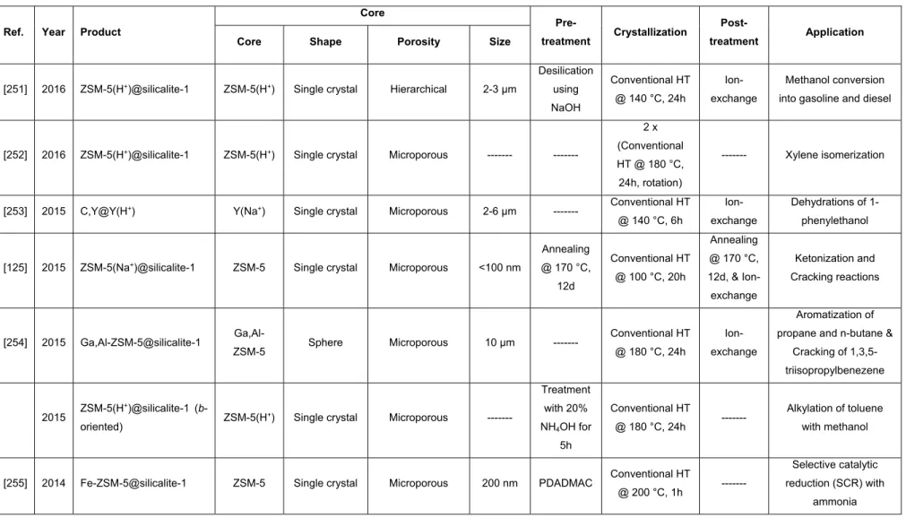
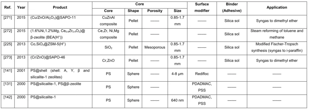
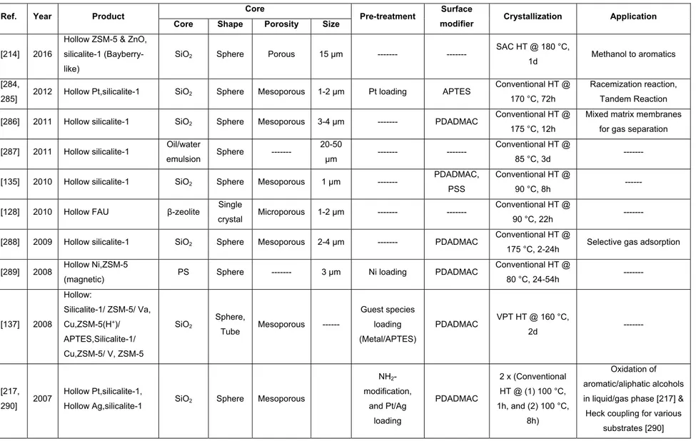
Table 1.1- Core@shell materials, synthesized using the seeded growth technique. ... 40 Table 1.2- Core@shell materials, synthesized using one-step (in-situ) zeolitic shell growth over the non-crystalline core. ... 48 Table 1.3- Core@shell materials, synthesized using zeolite overgrowth over the crystalline zeolitic shell. ... 54 Table 1.4- Core@shell materials, synthesized using the physical coating technique. ... 58 Table 1.5- Hollow and yolk-shell zeolitic materials, synthesized using the seeded growth technique.
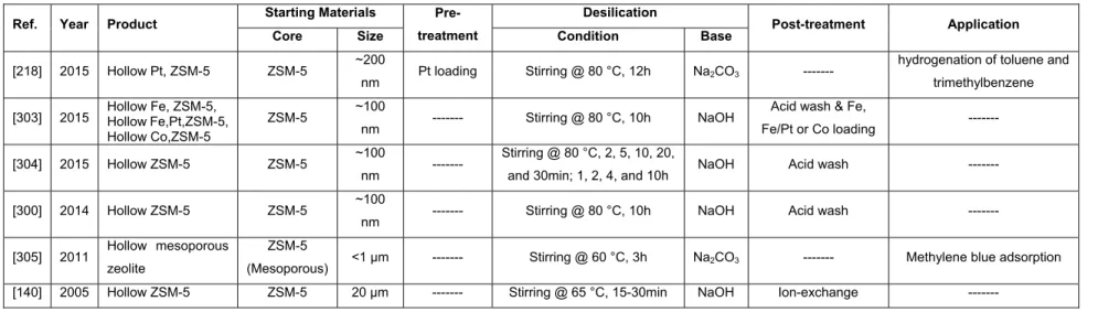
... 61 Table 1.6- Hollow and yolk-shell zeolitic materials, synthesized by using post treatment – Desilication.
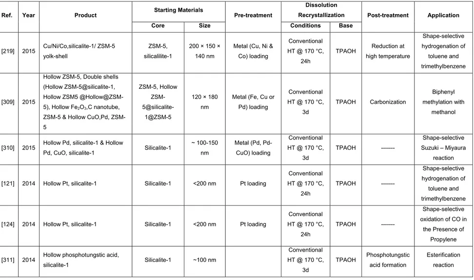
... 66 Table 1.7- Hollow and yolk-shell zeolitic materials, synthesized using post treatment – Dissolution- Recrystallization. ... 68 Table 2.1- ZSM-12 synthesis conditions using TEAOH as the organic templatea. The temperature
was set to 160 °C for all the syntheses. ... 103 Table 2.2- ZSM-12 synthesis conditions using MTEAOH as the organic templatea. The temperature
was set to 160 °C for all the syntheses. ... 112 Table 2.3- Textural properties of ZSM-12 samples. ... 126 Table 2.4- Thermogravimetric data for benchmarks as well as modified samples. ... 127 Table 3.1- Textural properties of the core@shell materials obtained by performing N2 physisorption
analysis at -196 °C. ... 151 Table 4.1- Textural properties of all the adsorbent materials obtained by performing N2 physisorption
xiii
List of Figures
Figure 1.1- (a) PBU, (b) SBU, and (c) CBUs which build (d) the framework of ZSM-12. ... 3 Figure 1.2- Nanozeolite synthesis routes (Reprinted with permission from [68]. Copyright 2013 RSC.).
... 16 Figure 1.3- Different types of transport-related hierarchy (Reprinted with permission from [73].
Copyright 2015 RSC.). ... 19 Figure 1.4- Overview of different strategies to implement mesoporosity in microporous zeolites: (a) inclusion of a secondary hard template in the form of rigid fibers, (b) incorporation of a secondary soft template, (c) application of a bifunctional template for micro-and mesostructuring, (d) covalent bonding of organosilane spacers to zeolite seeds, (e) formation of nanoparticle aggregates without secondary templates, and (f) post-synthetic leaching of alumina or silica species from premade zeolites (Reprinted with permission from [27]. Copyright 2013 RSC.). ... 20 Figure 1.5- Schematic representations of (a) core@shell, and (b) yolk–shell (Reprinted with
permission from [127]. Copyright 2014 Springer.). ... 29 Figure 1.6- (a) Schematic representation of the composite system. In the case of laterally oriented silicalite-1, the straight channels are perpendicular to the support. Silicalite-1 was directly synthesized on the metal oxide coated support using conventional hydrothermal treatment in a gel containing TPAOH, TEOS and water at 150 °C for 3h, (b) HRSEM photograph of silicalite-1 crystals grown with 200 nm of thickness and the average size of the laterally oriented intergrown crystals is 0.6 µm on a continuous layer of Fe2O3
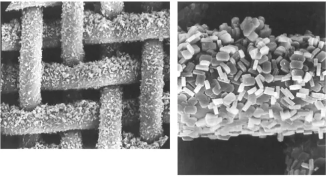
(Reprinted with permission from [119]. Copyright 1995 Elsevier.). ... 34 Figure 1.7- SEM images of the ZSM-5 zeolite coated on stainless steel wire gauze using the in-situ method. The wire diameter is 35 µm (Reprinted with permission from [169]. Copyright 2009 Wiley.). ... 36 Figure 1.8- Using controlled seeded growth technique to synthesize: (a) macroscopic c-axis oriented ZSM-5 hollow fibers (Reprinted with permission from [112]. Copyright 2013 ACS.), and (b) monolithic Al-fiber@ZSM-5(H+) (Reprinted with permission from [171]. Copyright
2015 Elsevier.). ... 37 Figure 1.9- Schematic representation of the seeded growth technique to synthesize the core@shell and hollow zeolites using (a) PS beads [133, 188] (Reprinted with permission from [133]. Copyright 2002 ACS.), and (b) mesoporous silica spheres [99, 100] (Reprinted with permission from [99]. Copyright 2003 Wiley.). ... 39 Figure 1.10- EMT@FAU all zeolite composite, formed by crystal overgrowth (Reprinted with
xiv
Figure 1.11- Preparation of CuZnAl@SAPO-11 catalyst by physical coating method (Reprinted with permission from [271]. Copyright 2015 Elsevier.). ... 57 Figure 1.12- (a) Scheme of making multifunctional nanoreactors by selective desilication (Reprinted with permission from [303]. Copyright 2015 Wiley.), and (b,c) SEM-EDS images of large crystal ZSM-5: (b) before alkaline treatment, (c) after alkaline treatment (Blue and yellow colors represent aluminum and silicon, respectively) (Reprinted with permission from [140]. Copyright 2005 ACS.). ... 65 Figure 1.13- (a) Schematic representation of a core@shell adsorbent, (b,c) SEM images of
β-zeolite@silicalite-1 composite, and (d) adsorption of butane, toluene, and trimethylbenzene (TMB) on β-zeolite@silicalite-1 (Reprinted with permission from [118]. Copyright 2005 Wiley.)... 71 Figure 1.14- Selective hydrogenation model of (a) xylene isomers over Pt,alumina@silicalite-1
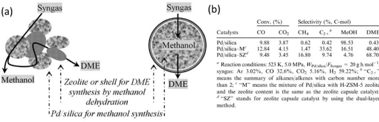
(Reprinted with permission from [195]. Copyright 2015 Elsevier.), and (b) toluene and TMB over hollow Pt,silicalite-1 (Reprinted with permission from [121]. Copyright 2013 RSC.). ... 73 Figure 1.15- (a) Illustration of tandem reaction process on general hybrid and capsule catalysts, and (b) catalysts performance in terms of activity and products distribution in tandem catalysis reaction (Reprinted with permission from [227]. Copyright 2011 RSC.). ... 74 Figure 1.16- (a) Scheme for the preparation of Al-TON@Si-TON zeolites, and (b,c) aluminum
distribution in a cross section of the core@shell zeolite: (b) A back-scattered electron image, and (c) map of the aluminum concentration measured by using WDS (Reprinted with permission from [247]. Copyright 2013 Elsevier.). ... 76 Figure 2.1- XRD patterns for (a) noncalcined TEA+-based benchmark (Benchmark-TEA+), (b,c)
calcined ZSM-12 synthesized using TEOS and different water contents (Sample 8: H2O/Si= 19 and Sample 9: H2O/Si= 13), and (d) effect of NaOH/Si on modified TEA+
-ZSM-12 (Sample 10). ... 106 Figure 2.2- SEM images of (a) TEA+-based benchmark (Benchmark-TEA+), (b) calcined ZSM-12
synthesized using TEOS and H2O/Si= 13 (Sample 9), (c,d) effect of NaOH/Si and TEA+/Si
on modified TEA+-ZSM-12 (Sample 10 and Sample 11, respectively). ... 107
Figure 2.3- XRD patterns for (a) noncalcined MTEA+-ZSM-12 benchmark (Benchmark-MTEA+), (b)
calcined ZSM-12 using Al(O-i-Pr)3 (Sample 12), (c) noncalcined ZSM-12 using
Al(O-i-Pr)3 and MTEAOH (Sample 14), and (d) effect of Si/Al on modified MTEA+-ZSM-12
(Sample 22). ... 113 Figure 2.4- SEM images of (a) MTEA+-ZSM-12 benchmark (Benchmark-MTEA+), (b) ZSM-12 using
Al(O-i-Pr)3 (Sample 12), (c) ZSM-12 using Al(O-i-Pr)3 and MTEAOH (Sample 14), and
xv
Figure 2.5- XRD patterns for calcined MTEA+-ZSM-12 at Si/Al= 30 and hydrothermal treatment
duration of (a) 84h (Sample 20), and (b) 144h (Sample 21)... 119 Figure 2.6- 29Si MAS-NMR curves of (a) MTEA+-ZSM-12 benchmark (Benchmark-MTEA+) and
modified MTEA+-ZSM-12, (b) Si/Al= 90 (Sample 14- noncalcined), (c) Si/Al= 30 (Sample
20, calcined), (d) Si/Al~ inf. (Sample 22-calcined), and (e) Si/Al= 90 (Sample 14- calcined). The signal intensities were normalized by the maximum intensity in each curve. ... 121 Figure 2.7- 27Al MAS-NMR curves of (a) MTEA+-ZSM-12 benchmark (Benchmark-MTEA+) and
modified MTEA+-ZSM-12 zeolites: (b) Si/Al= 90 (Sample 14- calcined), (c) Si/Al= 90
(Sample 14- noncalcined), (d) Si/Al= 30 (Sample 20, calcined), (e) Si/Al= 30 (Sample 20, noncalcined), and (f) Si/Al~ inf. (Sample 22-calcined). The signal intensities were normalized by the maximum intensity in each curve. ... 123 Figure 2.8- Nitrogen adsorption/desorption isotherms (-196 °C) for (a) MTEA+-ZSM-12 benchmark
(Benchmark-MTEA+) and modified MTEA+-ZSM-12 zeolites: (b) Si/Al= 90 (Sample 14),
(c) Si/Al= 30 (Sample 20), (d) Si/Al~ inf. (Sample 22). ... 125 Figure S 2.1- XRD patterns (effects of water content (S-1a- S-1f), and TEAOH content (S-1g) in the ZSM-12 synthesis using TEOS and TEAOH reagents). ... 130 Figure S 2.2- SEM images: effect of water content on products obtained after hydrothermal treatment of the gels produced using TEOS and TEAOH reagents (a-e: Sample 3-7). ... 131 Figure S 2.3- Nitrogen adsorption/desorption isotherms (-196 °C) for (a) benchmark-TEA+ sample,
and (b) modified TEA+-ZSM-12 (Sample 9). ... 132
Figure S 2.4- The evolution of crystalline ZSM-12 phase versus hydrothermal treatment time using MTEAOH as the organic template (Si/Al= 87). ... 133 Figure S 2.5- XRD patterns of the samples, synthesized using MTEA+ as organic template to study
the effect of (a) Na concentration on MTEA+- benchmark, (b) using Al(NO3)3.9H2O as Al
source, (c) water content and (d-f) using TEOS as Si source on modified gel (Sample 14). ... 134 Figure S 2.6- SEM images showing the effects of (a) reducing Na content and using Al(O-i-Pr)3
(Sample 13), and (b) using TEOS (Sample 17). ... 135 Figure S 2.7- SEM images of modified MTEA+-ZSM-12 samples, synthesized at Si/Al= 30 and
hydrothermal treatment duration of (a) 84h, and (b) 144h. ... 136 Figure S 2.8- Thermogravimetric (TG) and the corresponding first derivative (DTG) profiles obtained for benchmarks as well as modified ZSM-12 samples using both TEA+ and MTEA+
xvi
Figure 3.1- SEM images of (a,b) HMS@silicalite-1, (c,d) SG3@silicalite-1, and (e,f) SG20(II)@silicalite-1 after 2 and 4 successive secondary growth steps, respectively. ... 154 Figure 3.2- Nitrogen adsorption/desorption isotherms measured at -196 °C for synthesized
SG3@silicalite-1: (a,b) noncalcined samples after one and two successive secondary hydrothermal treatments, and (c,d) calcined samples after two and four successive secondary hydrothermal treatments. ... 156 Figure 3.3- SEM images of (a) Ti,HMS@silicalite-1, (b) Co,SG3@silicalite-1, (c)
Mn,SG3@silicalite-1, and (d-f) Co,SG20(I)@silicalite-1... 159 Figure 3.4- SEM images of (a,b) broken shell of Co,SG3@silicalite-1, (c,d) broken shell of
Co,SG20@silicalite-1, and (e,f) Co,SG3@silicalite-1 after four secondary growth steps. ... 161 Figure 3.5- Nitrogen adsorption/desorption isotherms measured at -196 °C for (a,b)
Co,SG20(I)@silicalite-1 before and after calcination, and (c,d) Ti,SG20(I)@silicalite-1 before and after calcination. ... 162 Figure 3.6- NLDFT pore size distributions and cumulative pore volumes of (a) silica gel-3 µm (SG3) (b) silica gel-20 µm (SG20(I)), in pure form, after metal insertion and after shell formation, calculated from the adsorption branch of the isotherm by using the NLDFT method. 164 Figure 3.7- XPS survey spectra of (a) bare Co,SG20(I), (b) partially covered Co,SG3@silicalite-1, (c) fully covered Co,SG3@silicalite-1, and (d) fully covered Co,SG20(I)@silicalite-1 (survey scans were used for apparent concentrations, presented as Co/Si ratio in the graph). ... 165 Figure 3.8- EDS elemental maps of (a-d) Co,SG3@silicalite-1 (Co/Si atomic ratio: 4%), and (e-h)
Co,SG20(I)@silicalite-1 (Co/Si atomic ratio: 1%). ... 166 Figure S 3.1- SEM images of (a) HMS microspheres, (b) silica gel spheres 3 µm (SG3), (c) silica gel spheres 20-45 µm (SG20) and (d-f) SG3 spheres containing (d) cobalt (Co,SG3), (e) manganese (Mn,SG3), and (f) titanium (Ti,SG3). ... 168 Figure S 3.2- Nitrogen adsorption/desorption isotherms measured at -196 °C for different core
particles. ... 169 Figure S 3.3- (a-c) SEM images of HMS, SG3 and SG20 particles, covered with silicalite-1
nanocrystals, (d) nitrogen physisorption isotherms (-196 °C) and (e) NLDFT cumulative pore volume plots of pure and noncalcined seeded HMS particles. ... 170 Figure S 3.4- Nitrogen adsorption/desorption isotherms measured at -196 °C (i) HMS and (ii) SG20 at different stages of the core@shell synthesis. ... 171
xvii
Figure S 3.5- SEM images of (a) Co,HMS@silicalite-1, (b) Co,SG3@silicalite-1, (c) Co,SG3@silicalite-1, (d) Mn,SG3@silicalite-1, (e) Co,SG20(I)@silicalite-1, and (f) Co,SG20(I)@silicalite-1 with higher magnification. ... 172 Figure S 3.6- Effect of multilayer polymer coating (PDADMAC/PSS/PDADMAC) on (a,b)
SG3@silicalite-1, and (c,d) Co,SG3@silicalite-1. ... 173 Figure S 3.7- Effect of the sole APTES modification on Mn,SG3@silicalite-1 synthesis after three
secondary growth steps. ... 174 Figure S 3.8- SEM images of Ti,SG20(I)@silicalite-1 after four secondary growth steps. ... 175 Figure S 3.9- Higher magnification HRSEM image of Co,SG20(I)@silicalite-1 sample, broken using a mortar and pestle. ... 176 Figure S 3.10- Nitrogen adsorption/desorption isotherms measured at -196 °C for (a,b)
Ti,HMS@silicalite-1 before and after calcination, and (c,d) Co,SG3@silicalite-1 before and after calcination. ... 177 Figure S 3.11- XRD patterns of Co,SG3@silicalite-1 and Co,SG20(I)@silicalite-1. Simulations for
calcined MFI structure were obtained from IZA website [56]. ... 178 Figure 4.1- (a) TEM image of silicalite-1 nanocrystals (scale bar= 0.2 µm), and SEM images of (b) HMS microspheres (scale bar= 10 µm), (c) silica gel spheres 3 µm (SG3) (scale bar= 10 µm), and (d) silica gel spheres 20-45 µm (SG20) (scale bar= 100 µm). Inset shows a higher magnification image. ... 194 Figure 4.2- SEM images of covered (a) SG20 spheres (scale bar= 10 µm) and (b) SG3 spheres with silicalite-1 nanocrystals, by using layer-by-layer technique (scale bar= 1 µm). Inset shows corresponding higher magnification image. ... 195 Figure 4.3- SEM images of (a) HMS@silicalite-1 (scale bar= 1 µm), (b) SG3@silicalite-1 (scale bar= 1 µm), and (c) SG20@silicalite-1 (scale bar= 10 µm). Inset shows corresponding higher magnification image. ... 196 Figure 4.4- (a) Nitrogen adsorption/desorption isotherms measured at -196 °C of (i) silica gel-3µm, (ii) core@shell before calcination, (iii) core@shell with a calcined shell, and (iv) silicalite-1 submicron crystals; (b) The corresponding NLDFT pore size distributions and cumulative pore volumes of (i) silica gel-3 µm (SG3), (ii) noncalcined SG3@silicalite-1, and (iii) calcined SG3@silicalite-1, calculated from the adsorption branch of the isotherm by using the NLDFT method. ... 200 Figure 4.5- Wide-angle powder XRD patterns for (a) bare HMS, (b) coated HMS before hydrothermal treatment, (c) core@shell particles after secondary growth, and (d) silicallite-1 nanocrystals. ... 204
xviii
Figure 4.6- Specific adsorption loading of glycerol at equilibrium for different adsorbents by using methanol-free biodiesel at 25 °C (glycerol initial concentration in biodiesel = 0.065 wt%, adsorbent concentration= 2.3 wt%). ... 207 Figure 4.7- Overlay of thermogravimetric curves for the used adsorbents (glycerol initial concentration in biodiesel = 0.065 wt%, adsorbent concentration= 2.3 wt%). ... 209 Figure 4.8- Specific uptake of FAME at equilibrium for different adsorbents using methanol-free
biodiesel at 25 °C (glycerol initial concentration in biodiesel = 0.065 wt%, adsorbent concentration= 2.3 wt%). ... 210 Figure 4.9- Uptake of FAMEs by different adsorbents from methanol-free biodiesel at different
temperatures (glycerol initial concentration in biodiesel = 0.065 wt%, adsorbent concentration= 2.3 wt%). ... 213 Figure 4.10- Adsorption of glycerol by different adsorbents from methanol-free biodiesel at different temperatures (glycerol initial concentration in biodiesel= 0.065 wt%, adsorbent concentration= 2.3 wt%). ... 214 Figure 4.11- Adsorption of Glycerol and FAMEs by using different adsorbents from
methanol-containing biodiesel at room temperature (glycerol initial concentration in biodiesel = 0.22 wt%, methanol content ~ 0.7 wt%, adsorbent concentration= 2.5 wt%). ... 215 Figure 4.12- Adsorption of glycerol from methanol-containing biodiesel at different temperatures
(glycerol initial concentration in biodiesel = 0.22 wt%, methanol content ~ 0.7 wt%, adsorbent concentration= 2.5 wt%). ... 217 Figure 4.13- Uptake of FAMEs from methanol-containing biodiesel at different temperatures (glycerol initial concentration in biodiesel = 0.22 wt%, methanol content ~ 0.7 wt%, adsorbent concentration= 2.5 wt%). ... 218 Figure S 4.1- Silicalite-1 nanocrystal size distribution by intensity (dynamic light scattering (DLS)
measurements were performed using a Malvern Zetasizer Nano ZS particle analyzer (equilibration time set to 2 min; measurements repeated 3 times; only data which passed quality criteria accepted as valid results)). ... 220 Figure S 4.2- SEM image of Si-BEA microcrystals (scale bar= 10 µm) ... 221 Figure S 4.3- SEM image of Al-ZSM-5(H) microcrystals (scale bar= 10 µm) ... 222 Figure S 4.4- Nitrogen adsorption/desorption isotherms measured at -196 °C of (i) HMS spheres, (ii) core@shell before calcination, and (iii) core@shell with a calcined shell ... 223 Figure S 4.5- The corresponding NLDFT pore size distributions and cumulative pore volumes of (i) HMS spheres, (ii) noncalcined HMS@silicalite-1, and (iii) calcined HMS@silicalite-1, calculated from the adsorption branch of the isotherm by using the NLDFT method. 224
xix
Figure S 4.6- Nitrogen adsorption/desorption isotherms measured at -196 °C of (i) silica gel-20µm, (ii) core@shell before calcination, and (iii) core@shell with a calcined shell. ... 225 Figure S 4.7- The corresponding NLDFT pore size distributions and cumulative pore volumes of (i) Silica gel-20 µm (SG20), (ii) noncalcined SG20@silicalite-1, and (iii) calcined SG20@silicalite-1, calculated from the adsorption branch of the isotherm by using the NLDFT method. ... 226 Figure S 4.8- Wide-angle powder XRD patterns for (a) bare SG3, (b) coated SG3 before hydrothermal treatment, and (c) core@shell particles after secondary growth. ... 227 Figure S 4.9- Wide-angle powder XRD patterns for (a) bare SG20, (b) coated SG20 before
hydrothermal treatment, and (c) core@shell particles after secondary growth. ... 228 Figure 5.1- (a) Specific uptake of FAME and glycerol at equilibrium for different adsorbents using
methanol-free biodiesel at 25 °C (glycerol initial concentration in biodiesel = 0.065 wt%, adsorbent concentration= 2.3 wt%). (b) Schematic representation of selective adsorption of glycerol by diffusing through the microporous silicalite-1 shell. ... 234 Figure App 1- Schematic representation of the S0I0 templating mechanism of formation of HMS
xx
List of Schemes
Scheme 3.1- Schematic representation of the synthesis of metal-containing mesoporous silica@silicalite-1. ... 146 Scheme 4.1- Schematic representation of the mesoporous silica@silicalite-1 synthesis ... 184
xxi
Abbreviations
1D One-dimensional
2D Two-dimensional
3D Three-dimensional
3DOM Three-dimensionally ordered meso/macroporous carbons
acac Acetylacetone
Al(O-i-Pr)3 Aluminum isopropoxide
ALPO Aluminophosphate
Al-ZSM-5(H) Proton-exchanged ZSM-5 zeolite with Bronsted sites
APTES (3-aminopropyl)triethoxysilane
APTMS (3-aminopropyl)trimethoxysilane
ASTM American society for testing and materials
BEA(H+) Proton-exchanged β-zeolite
BET Brunauer-Emmett-Teller method
CBU Composite building unit
CIT-5 California institute of technology number five
CMK-x Carbon molecular sieves Korean advanced institute of science and technology number x
CTAB Cetyltrimethylammonium bromide
CZA Cu,ZnO,Al2O3 composite
DG Diglycerides
DGC Dry gel conversion techniques
DIR-MCFC Direct internal reforming molten carbonate fuel cell
DLS Dynamic light scattering
dp Pore size
DSC Differential scanning calorimetry
DTG Differential thermogravimetry
EDS Energy-dispersive X-ray spectroscopy
FAME Fatty acid methyl esters
FCC Fluid catalytic cracking
FDU-x Fudan University ordered mesoporous materials series
FFA Free fatty acid
FID Flame ionization detector
FSM Folded Sheet Materials
FTC Framework type code
GUM Guide to the expression of uncertainty in measurement
HRSEM High resolution scanning electron microscopy images
HT Hydrothermal treatment
IMS Isomorphous metal substitution
ITQ-x Instituto de Tecnologıa Quımica zeolite series
IUPAC International Union of Pure and Applied Chemistry
xxii
KIT-6 Korea Advanced Institute of Science and Technology cubic ordered mesoporous silica
LBL Layer-by-layer technique
M Metal guest species (Ti, Co and Mn)
M41S Generic term for Mobil composition of matter materials
MAPO Metalloaluminophosphate
MAS Magic angle spinning
MCM-x Mobil composition of matter number x
MG Monoglycerides
MOF Metal-organic framework
MOR(H+) Proton-exchanged MOR zeolite
MSU-H Michigan state university hexagonal material
MTEA+ Methyltriethylammonium cation
MTEACl Methyltriethylammonium chloride salt
MTEAOH Methyltriethylammonium hydroxide
ND-1 University of Notre Dame number 1
NLDFT Non-local density functional theory
NMR Nuclear magnetic resonance
OMC Ordered mesoporous carbons
OMM Ordered mesoporous material
PBU Primary building units
PDADMAC Poly(diallyldimethylammonium chloride)
PDVB Poly(divinylbenzene)
PEG Polyethylene glycol
PMMA Poly(methyl methacrylate)
PS Polystyrene
PSS Poly (styrenesulfonate, sodium salt)
RC Relative crystallinity
RT Room temperature
SAC Steam-assisted technique
SAPO Silicoaluminophosphates
SBA-x Santa Barbara mesoporous silica series
SBU Secondary building units
SDA Structure-directing agent
SEM Scanning electron microscopy
SG Silica gel
SG20 Commercial silica gel spheres with particle diameter 20-45 µm
SG20(I) SG20 spheres with dp ~7nm SG20(II) SG20 spheres with dp ~10 nm SG3 Commercial silica gel spheres 3µm
Si/Al ratio Silicon to aluminum ratio in zeolite framework
Si-BEA Pure silica β-zeolite
xxiii
TEA+ Tetraethylammonium
TEABr Tetraethylammonium bromide salt
TEAOH Tetraethylammonium hydroxide
TEM Transmission electron microscopy
TEOS Tetraethyl orthosilicate
TGA Thermogravimetric analysis
TG Triglycerides
TMAOH Tetramethylammonium hydroxide
TMB Trimethylbenzene
TNBT Titanium (IV) butoxide
TPA+ Tetrapropylammonium cation
TPAOH Tetrapropylammonium hydroxide
TS-1 Titanium silicalite-1
UTD-1 University of Texas at Dallas number one
VPI-5 Virginia Polytechnic Institute number five
VPT Vapor phase transport
XPS X-ray photoelectron spectroscopy
XRD X-ray diffraction
xxiv
Acknowledgments
My sincerest thanks and appreciation go to my advisors Prof. Freddy Kleitz, Prof. Serge Kaliaguine and Dr. Pablo M. Arnal.
I would like to express my deep appreciation and gratitude to my advisor, Prof. Kleitz, to whom I am indebted for granting me an opportunity to work in his group on an area I have been passionate about and for providing me with patient guidance, mentorship, unstinting support and freedom throughout my Ph.D. study.
I wish to express my gratitude to Prof. Kaliaguine who has been a great source of wisdom and encouragement for me. He was always willing to spend time discussing my research and helping me learn. I am very fortunate to have had the opportunity to work with him.
I would like to express my sincere gratitude to Dr. Arnal for his time, support and feedback on various aspects of this project.
I would also like to express my gratitude to my Ph.D. committee members, Prof. Kenneth J. Balkus, Prof. Trong-On Do and Dr. François Béland, for their time and efforts to go over my research work. I would like to acknowledge the great assistance of Dr. Kyoungsoo Kim from Institute for Basic Science (IBS), South Korea for providing the HRSEM images.
I would like to thank professors, administrative staff, research professionals and technicians of the Department of Chemical Engineering and Department of Chemistry, Université Laval, for the kind help I received during my Ph.D. work. In particular, I would like to express my sincere gratitude to Mr. Pierre Audet, Mr. André Ferland, and Mr. Richard Janvier for their great assistance and training. None of this work would have been possible without the support and help of the group members, both past and present. I would like to thank all my friends and colleagues at Laval University, especially, Dr. Jean-Luc Bridot, Meryem Bouchoucha, KarimKhadhraoui, Maëla Choime, Solange Schneider, Dr. Pablo Lebeld, Dr. Cao Thang-Dinh, Louis Lefrancois Perreault, Xu Wan, Thanh-Binh Nguyen, Fanny Silencieux, François Chalifour and Dr. John Dupont. It has been a real pleasure working with you all.
In particular, I wish to thank Dr. Hoang Yen, Dr. Justyna Florek, Dr. Remy Guillet-Nicolas, Dr. Simon Giret, Dr. Mahesh Nair, Estelle Juere and Maria Zakharova for their valuable discussion, support and friendship over the years.
Finally, I would like to thank my family for all their never-ending spiritual support and encouragement. I would like to thank my wife, the best friend of mine, Forough, for her endless support and innumerable sacrifices.
xxv
Foreword
This study aims at the design of more efficient zeolitic materials by either finding better- controlled conditions for traditional crystallization processes or designing and synthesizing high-quality structured zeolitic composites. In the first part, ZSM-12 was chosen as one of the most interesting large-pore 1D zeolites. Compared to other zeolites, such as ZSM-5, ZSM-12 has been scarcely studied. Considering the original verified synthesis method of ZSM-12 (published in the late 80s), most of the subsequent studies did not achieve significant improvements in terms of synthesis conditions (for instance, crystallization under less harsh conditions), the cost of the synthesis (shorter crystallization process, less-expensive SDAs, etc.) and controlling material properties, such as crystal size and shape, etc. On the other hand, using ZSM-12 has unfolded its versatility and efficacy in many applications. This has encouraged us to investigate various synthesis conditions to gain more insights into ZSM-12 crystallization behavior and hopefully attain better control of parameters that determine its performance in real practical applications, such as crystal morphology. The results of this study, recently published in the journal Microporous and Mesoporous Materials, are reported in Chapter two of the thesis.
Zeolitic core@shell materials have become popular in the past decade and used for many applications. In the second part of this study, the viability of complete encapsulation of mesoporous silica spheres using a microporous zeolitic shell was studied. Owing to exceptional properties of mesoporous silica spheres, such as high surface area and pore volume, synthesizing such a structure and the ability to tune its properties such as shell thickness, uniformity, activity, etc., will open new pathways in the field of catalysis and adsorption. Of course, this is not an easy task and it faces many problems including chemical incompatibilities with the zeolite crystallization conditions and pore network communication which have been brought up in the literature for similar materials (zeolite@zeolite). To address these issues, a thorough study of different synthesis parameters was performed and the results are reported in Chapters three and four of this thesis.
This dissertation is composed of five chapters. The first chapter starts with a brief introduction about classical zeolitic materials and describes the challenges which limit their application, especially the ongoing struggles with mass-transfer issues. This section is followed by reviewing the current state-of-the-art approaches which target those issues.
xxvi
Chapters two, three and four of this dissertation report the experimental results, interpretations and discussions, in the form of three scientific articles of which the candidate is the primary author. These publications are outlined below:
Chapter 2: “Synergy between structure direction and alkalinity toward fast crystallization, controlled morphology and high phase purity of ZSM-12 zeolite”, Nima Masoumifard, Serge Kaliaguine and Freddy Kleitz, published in Microporous and Mesoporous Materials, 227 (2016) 258-271.
Chapter 3: “Synthesis of Microporous/Mesoporous Core-Shell Materials with Crystalline Zeolitic Shell and Supported Metal Oxide Silica Core”, Nima Masoumifard, Kyoungsoo Kim, Serge Kaliaguine, Pablo Arnal and Freddy Kleitz, published in CrystEngComm 18 (2016) 4452-4464.
Chapter 4: “Zeolitic Core@Shell Adsorbents for the Selective Removal of Free Glycerol from Crude Biodiesel”, Nima Masoumifard, Pablo Arnal, Serge Kaliaguine and Freddy Kleitz, published in ChemSusChem 8 (12) (2015) 2093-2105.
In these scientific papers, the candidate conducted the experimental works under the supervision of Prof. Freddy Kleitz, Prof. Serge Kaliaguine and Dr. Pablo Arnal. The high-resolution SEM images, presented in Chapter three, were taken by Dr. Kyoungsoo Kim from Institute for Basic Science (IBS), South Korea, who was also the co-author of this paper. The candidate who is the first author of the above papers has performed all of the experiments, collected the data and prepared the first drafts of all manuscripts. All the authors revised the manuscripts prior to publication.
Finally, chapter five completes this dissertation by providing overall conclusions along with some recommendations for future work.
1
Chapter 1- State-of-the-art
1.1 Introduction
The term “engineered zeolitic materials” refers to a class of material with rationally designed pore system and active site distribution. They are primarily made of crystalline microporous zeolites as the main building blocks which can be accompanied by other secondary components to form composite materials. The first section of the current chapter starts with providing general information about zeolite structure, properties and conventional synthesis methods, followed by discussing the motivating rationale behind the growing demand for structural alteration of the classical zeolitic materials. The main techniques that are currently available for such modifications are briefly reviewed in Section 1.3. Core@shell composites as one of the pathways toward creating a new generation of highly versatile and efficient engineered zeolitic substances are introduced in Section 1.4. Sections 1.5 and 1.6 summarize the synthesis approaches, developed so far, for making zeolitic core@shell and its analogues, yolk-shell and hollow materials. Section 1.7 reviews the findings around the performance of these materials, obtained from conducting laboratory-scale experiments.
1.2 Zeolites as Ordered Microporous Materials
The presence of the pores as tiny passages within a solid body has created a special class of substances with extraordinary characteristics, the so-called porous materials. The internal pore dimension (dp) has initially been used, by IUPAC1 organization, as a simple criterion to
categorize all porous materials into three groups: microporous (dp < 2 nm), mesoporous (dp
~ 2-50 nm) and macroporous (dp > 50 nm) materials [1, 2]. The term nanoporous has also
been introduced to describe the materials which have pores in nanometer size range (dp <
100 nm), however, it is mainly referring to microporous and mesoporous classes together (dp < 50 nm).
2
Microporous materials, also known as molecular sieves, are the most important members of porous materials owing to their outstanding property of having size-discrimination capability at the molecular level. Despite the existence of various types of microporous materials, such as carbon-based materials, MOFs1 and polymers, zeolites are still the most well-known and widely-used microporous solids. Zeolites are low-density, crystalline aluminosilicates with an ordered microporous structure, i.e., an extremely narrow and uniform pore size distribution [3-6].
1.2.1 Zeolite History
In 1756, A.F. Cronstedt, a Swedish mineralogist, discovered a special naturally-occurring crystalline aluminosilicate and described it as “Zeolite” since it released a significant amount of tiny bubbles upon heating [4]. The word “Zeolite” is actually a compound noun, made up of two separate ancient Greek words: “zeo” meaning “to boil” and “lithos” meaning “a stone”. After then, various types of naturally occurring zeolites (around 50 so far) were found in rock, until about 200 years later in the 1940s, the first synthetic zeolite (ZK-5 (KFI)) was successfully made in hydrothermal conditions (high pressure and temperature) by R. M. Barrer [7]. Shortly after two industrially important synthetic zeolites, i.e., zeolite A and X, were synthesized by R. Milton [8, 9]. After these pioneering works, the field of zeolite science truly started and grew massively by finding several new structures every year. Over the last 70 years, over 200 synthetic zeolites and their isomorphic relatives, i.e., zeotypes2, such as aluminophosphates (ALPOs), silicoaluminophosphates (SAPOs) and other metalloaluminophosphate (MAPO), have been identified as a separate group of minerals, synthesized and used on large-scale in many industrial processes [10].
However, the term zeolite was originally used for crystalline aluminosilicate materials, it has evolved and broadened to cover all newly-discovered structures and compositions including non-aluminosilicate zeotypes [10]. Today, the term “zeolitic material” is also used to denote
1- Metal Organic Framework
2- The term zeotype is widely used to name molecular sieves that show many structural similarities to typical aluminosilicate zeolites, but having elements other than Si and Al as the framework building units.
3
all classical zeolites, zeotypes and new compositions and structures [11]. Therefore, both zeolite and zeolitic materials will be used interchangeably here throughout the text.
1.2.2 Zeolite Structure
Zeolites are basically made of TO4 tetrahedra, i.e., the primary building units (PBUs) in which the T atom, including Si, Al or some other elements like P, V, Ti, Ga, Ge, B, is covalently bonded to four oxygen atoms, e.g., [SiO4]4- and [AlO4]5- tetrahedra. These TO4 building units are then linked together via covalent bonding to form the secondary building units (SBUs) and composite building units (CBUs). In contrast to CBUs, the SBU units which contain up to 16 T atoms, were found by assuming that the entire framework is made of one type of SBU only in a repetitive manner [12]. There are presently 23 observed SBUs as reported in [12, 13] (Figure 1.1). It is also possible to imagine that a single zeolitic framework is constructed from the attachment of various more complex units together, the CBUs, such as cages, chains, cavities and channels [12, 13]. Rings can be considered as the simplest building units (SBU or CBU), constructed from n TO4 units where n is usually equal to 4, 5, 6, 8, 10 and 12 [14], forming transport windows of molecular dimensions with a maximum opening of about 0.7 nm in aluminosilicate zeolite. In zeotypes, however, larger windows can be formed, for instance, an extra-large window of thirty TO4 tetrahedra (30-ring windows) has recently been reported for germanosilicate zeolite (ITQ-371) [15] (Figure 1.1).
Figure 1.1- (a) PBU, (b) SBU, and (c) CBUs which build (d) the framework of ZSM-12.
4 1.2.3 Zeolite Classification
Characteristic crystallographic data of zeolitic materials were initially used to identify the distinct types of the frameworks which were later documented by the structure commission of the International Zeolite Association (IZA) and published in “Atlas of Zeolite Framework Types” database [12] or on the regularly-updated IZA website [16]. A three letter Framework Type Code (FTC) is assigned by IZA to each unique identified zeolite topology, which has currently reached to over 230 framework types of zeolites and zeotypes. It should be noted that FTC just refers to the framework type, i.e., different zeolitic materials with various compositions can be called by the same code if they share a framework type.
The orderly perforated structure of the zeolites can also be categorized using other properties such as dimensionality of the micropore network, the size of the micropore opening (the window) and chemical compositions, as briefly discussed below.
Depending on micropore interconnectivity and dimensions, zeolites can be divided into three groups including one-, two-, or three-dimensional (1D, 2D and 3D). The micropore opening (size and topology) is directly related to the number of TO4 units on the ring which forms the window. In this regard, aluminosilicate zeolites have been classified into small pore zeolites with eight-membered oxygen ring pore window (8-ring), medium pore zeolites with ten-membered oxygen ring pore window (10-ring) and large pore aluminosilicates with twelve-membered-ring pore window (12-ring). There is also an extra-large pore zeolite category with TO4 units above 12 for phosphates and germanosilicates, e.g., ND-1 with 24 [17], ITQ-43 with 28 [18] and ITQ-37 with 30 elements [15] are the highest reported so far. This number of TO4-elements on the ring leads to zeolites and zeotypes with various pore sizes, for instance, aluminosilicates with pores between 0.3 and 0.7 nm, and germanosilicates up to 2 nm [18]. In general, micropores are divided into two main groups: ultramicropores which are smaller than about 0.7 nm and supermicropores with the size range between 0.7 and 2 nm [2]. Regarding the pore sizes in each direction of a multidimensional zeolite, zeolitic materials were also classified into uni-modal micropore system such as zeolite Y and ZSM-5 and multi-modal micropore system such as MCM-22 [19].
The chemical composition of a zeolite is also a determinant parameter and can affect various zeolite properties. The chemical composition of a specific framework type can be altered by either changing the ratio between major building elements (Si, Al or P) within a limited range
5
or substituting those main elements with other (MIII and MIV) such as B, Ti, V, Cr, Mn, Fe, Zn, Ga, Ge, and Zr, etc., [11, 20] via isomorphous substitution. These compositional variations have also been used to classify zeolitic materials into different groups, for instance, the Si/Al ratio in low silica zeolites is Si/Al= 1.0-1.5, in intermediate silica zeolites is Si/Al= 2.0-5.0 and in high silica ratio zeolites is Si/Al> 10 - which also includes all-silica zeolite with Si/Al> 100 [10, 21].
1.2.4 Zeolite Properties
As mentioned earlier, the chemical composition (T elements involved) and the way TO4 tetrahedral units are linked to each other could provide various frameworks with different properties. According to the requirements imposed by various applications, these intrinsic properties, briefly discussed below, can be uniquely tuned, an opportunity that makes zeolites special compared to other inorganic oxide materials.
- High internal surface area and pore volume: All great properties of zeolitic materials are directly related to their porous structure, providing high surface area and voids which can host various type of species.
- Shape selectivity characteristic: Uniformly-sized and distributed micropores which are comparable to the size of a small molecule create a size/shape-selective adsorbent or catalyst. The molecular shape selectivity can have a significant influence on a reaction through various mechanisms such reactant, product or transition-state selectivity [22]. In addition, the existence of pore mouth and key-lock catalysis on selective distribution of the products have also been demonstrated [23]. In this case, reactants are more adsorbed on the pore mouth rather than diffusing into the zeolite bulk. Multidimensional microporous zeolite with various sizes in each direction (known as multi-modal micropore systems or simply multipore zeolite) could also provide a very selective network by favoring a guided diffusion of reactants and products through different channel systems depending on their size differences, known as “molecular traffic control” mechanism [24]. This property can lead to more advanced shape-selectivity by combining molecular traffic control feature with direction-dependent active site distribution within the pores, cavities and side pockets of a
6
multipore zeolite [24]. More details about multipore zeolites and their catalytic applications can be found elsewhere [19, 24].
- Single-file diffusion: Although multi-dimensional zeolites bring higher surface area and better accessibility to active sites, 1D zeolites can provide better trapping ability of molecules when strong adsorption is not feasible, i.e., efficient trapping of small molecules instead of adsorption and releasing them when it is needed [25].
- Ion-exchange capacity: The framework charge imbalance, e.g., caused by aluminum atoms as T-element in a zeolite, needs to be neutralized by a stoichiometric amount of extra-framework charge compensating counter-ions, such as H+, Li+, Na+, K+, Rb+, Cs+, Be2+, Mg2+ and Ca2+ or transition metal elements. These cations are mobile and can be exchanged with another cation of interest from a solution in a reversible manner [26].
- Internal acidity: Exchanging the metal cation with proton (H+) can create strong Bronsted acidic centers on the zeolite surface, especially in Si-rich aluminosilicates. Another interesting feature of these zeolitic acid sites is their even distribution throughout the surface of a zeolite. Lewis acid sites can also be generated within the porous structure of a zeolitic material via ion-exchange or isomorphic substitution of several isolated metal centers such as titanium, tin or zirconium [24].
- Tunable chemical composition: Tuning of the chemical composition of a zeolitic material directly controls its properties. For instance, an Al-rich zeolite provides huge exchange capacity which makes it an ideal separator of cations and polar impurities from a solution. A Si-rich zeolite, on the other side, if neutralized by a proton, is more favorable acid catalysts because of their higher thermal stability (required for high-temperature reactions and regeneration processes) and higher affinity toward adsorbing less polar molecules. In addition, optimum dispersion of acid sites with higher strength is ensured by their low Al content of the framework [27].
- Isomorphous metal substitution (IMS): IMS refers to a situation that one of the major elements Si, Al and P in a zeolitic framework is replaced by a wide variety of heteroatoms such as Be, B, Ti, V, Cr, Mn, Fe, Co, Zn, Ga, Ge and Zr [11]. The presence of these elements can drastically change zeolite properties [28]. Moreover, this heteroatom substitution has
7
constantly helped to discover new zeolitic frameworks such as germanates and MAPOs with no zeolite or ALPO analogues [29].
- High chemical, mechanical, thermal and hydrothermal stability.
- Easy regeneration: Depending on the deactivation source, they can be easily regenerated
with the minimum damage to the zeolitic structure via heat treatment (calcination), ion-exchange or pressure swing.
- Supporting other guest species to make bi-functional catalysts
- Biocompatibility and low toxicity
Due to all these exclusive properties, these materials have been massively used for industrial applications, e.g., adsorption, purification, separation, catalysis and ion-exchange [10, 30-33] and there are continuous efforts for improving the existing zeolitic materials and also finding new frameworks.
1.2.5 Zeolite Synthesis
The first step usually involves the preparation of a mixture consisting of all reagents, properly blended and conditioned toward the formation of an amorphous gel phase and/or precursor mixture. Silicates and aluminates species, a mineralizer (OH¯ /F¯) and organic/inorganic structure-directing agents (SDA) are the main constituents of this gel which is homogeneously mixed together using mainly water as the solvent. Depending on the type of zeolite and gel composition, an aging step under specific conditions, mainly ambient, might be necessary before the final crystallization period starts.
Next step is the conversion of the as-prepared gel into zeolitic materials which mostly occurs by aging the mixture inside tightly closed (sealed) vessels, frequently at elevated temperatures and autogenous pressures. Depending on the chosen synthesis method, i.e., conventional hydrothermal treatment or dry gel conversion techniques (DGC), solvents can be partially or completely removed from the gel prior to high-temperature crystallization reaction. In DGC technique, a completely dried gel is placed on a support inside an
8
autoclave containing liquid phase in a way that direct mixing of two phase is avoided. The liquid phase in the bottom of the container can contain either an aqueous mixture of organic SDAs which can be later volatilized to reach the dried zeolite gel and promote zeolite formation, known as vapor phase transport (VPT) technique or, in case of non-volatile organic SDAs, simply pure water to produce required steam for zeolitization1 of the dry gel, known as steam-assisted technique (SAC). In general, this technique has some beneficial aspect compared to conventional hydrothermal treatment including less SDA usage, higher yield and achieving higher metal incorporation into the framework (lower Si/Al). Moreover, it is found to be extremely helpful for proper implementation of the techniques proposed for hierarchical zeolite synthesis (discussed later in Section 1.3). This method has some disadvantages including non-uniform crystallization within the gel leading to amorphous impurities in the final product as well as scale-up issues [27]. The former is caused by a decrease in the mobility and interaction of the precursor species as a direct consequence of removing the solvent.
Finally, after washing and recovery of the product, a high-temperature calcination is mainly required to remove the organic templates from the pores, if any used. The calcination conditions (temperature and atmosphere) can also affect the properties of the product. In contrast to mesoporous silica (e.g., MCM-41 [34]), chemical extraction of the organic template is not viable unless some especially-designed organic template is used [35].
With slight modifications at different steps of the synthesis procedure, it is also possible to synthesize transition metal-containing (-exchanged, -substituted, and/or -impregnated) zeolites. A recent review by Li et al. [29] summarizes new synthesis strategies proposed over the last decade resulting in the discovery of new zeolitic materials.
1.2.5.1 Formation Mechanism and Key Synthesis Elements
Zeolite synthesis protocols were essentially discovered and optimized through trial and error approach. Therefore, understanding the mechanism and key elements can enormously enlighten the path toward rational design of new structures and optimization of the existing
9
methods. There are ongoing efforts to gain more insights into the mechanism behind the crystallization of the zeolites from the gel which is still a matter of controversy. In general, zeolite crystals form during the crystallization process through various sequential steps including the pre-nucleation step, primary nucleation, the growth of the nuclei to larger sizes and finally the growth of the crystals which can sometimes be accompanied by simultaneous secondary nucleation. The driving force behind all these processes are related to supersaturation phenomenon, also occurring during the pre-nucleation step, a condition which is very difficult to study. In general, the pre-nucleation step includes complete/partial dissolution/hydrolysis of Si and Al sources followed by condensation of amorphous oligomeric silicate and aluminate species, also known as zeolite precursors and finally reaching a so-called supersaturation condition. Primary nucleation as a second step can occur either homogeneously within the solution gel and grow progressively by nourishing from dissolved species from liquid phase or heterogeneously within solid-like materials present in the gel and grow by solid-solid transformation. In the latter case, the gel can be entirely in the solid phase, i.e., an amorphous hydrogel. The last step is the crystal growth which small crystalline nuclei starts to rapidly grow by absorbing available Si-containing units from the gel through a layer-by-layer mechanism. Secondary nucleation may occur at this stage by these crystals. Most of the studies around zeolite formation mechanism were done for simple reaction system, however, the mechanisms of nucleation and crystal growth processes are generally governed by many factors and might be different from one framework type or even one synthesis condition of a specific type of zeolite to another. Such comprehensive understanding of the zeolite formation processes is something yet to be accomplished. More information about zeolite crystallization mechanisms can be found elsewhere [6, 36].
The major factors that influence the formation of zeolites are crystallization temperature, time, reagent sources, impurities and concentrations, seeding, SDAs and alkalinity. SDAs are highly vital for zeolite formation. Various chemicals in synthesis mixture can provide such an effect alone or in a cooperative manner [37]. They can be classified as one of the following groups: charged molecules mainly cations (Organocations): they are also known as organic templates, primarily alkylammonium cations. They were first introduced by Barrer and Denny in 1961 [38]. Using this type of material was one of the key discoveries in the field of zeolite synthesis, leading to new synthesis routes, new frameworks and enhancing original properties such as widening the range of Si/Al ratio possible. Regarding their size
10
compared to pore dimensions, they can be considered as templates and pore-filling agents in some cases as well. They are the most popular SDAs. Inorganic cations, e.g., alkali and alkaline earth metal cations, which are mainly introduced to synthesis mixture in the forms of basic compounds to adjust the pH, can have significant effects on nucleation and crystal growth. In addition to this cationic species, neutral molecules such as water, amines, etc., and ionic pairs such as salts can also play templating roles by stabilizing a specific type of zeolitic framework. A list of newly developed pre-synthesized SDAs can be found in a recent review [29]. Other than its complex role in stabilizing the zeolitic structure and interactions with cationic SDAs (hydrating effect), water is also serving as the most popular solvent used in zeolite synthesis. Another key element is the alkalinity (OH¯) which affects the crystallization process in many ways. Under the influence of this parameter, the amorphous part of the gel is depolymerized to form oligomeric species in the solution. These solubilized species can provide supersaturation condition required for nucleation and crystal growth. It also plays a mineralizing role toward proper and faster condensation of aluminosilicate species into a more stable solid phase, the nuclei. These hydroxyl ions can also improve the crystal growth rates. The crystal phase, composition (Si/Al), morphology and crystallization yield are also other parameters which can be affected by alkalinity. Incorporation of other elements, especially aluminum can also have a great effect, not only on zeolite formation but also on the products properties such as morphology and physicochemical properties. Therefore, proper Al concentration should be adjusted within the synthesis gel, which requires many trials since the Si/Al ratio in the gel and the final product may differ. The reason is that Al incorporation might be controlled by some other factors such as alkalinity, counter ion concentration, type of framework, etc., rather than being proportional to the Al concentration.
For certain types of zeolites, it was shown that addition of already formed crystals (seed) with similar framework structures could speed up the crystallization process via either secondary nucleation phenomenon or eliminating the nucleation step by promoting faster (inter)growth of the seeds. Due to the structure-directing effect of the seeds in some cases, sometimes this technique, partially or completely, eliminates the need for organic SDAs [39]. In this way, environmental concerns in contact with the usage of organic SDAs can be avoided. More details about green routes of zeolite synthesis can be found in reference [40].
![Figure 1.9- Schematic representation of the seeded growth technique to synthesize the core@shell and hollow zeolites using (a) PS beads [133, 188] (Reprinted with permission from [133]](https://thumb-eu.123doks.com/thumbv2/123doknet/5843292.141679/65.918.153.791.106.472/figure-schematic-representation-technique-synthesize-zeolites-reprinted-permission.webp)