EUROSTEEL 2014, September 10-12, 2014, Naples, Italy
BOLTED END-PLATE BEAM-TO-COLUMN JOINTS USING
HAMMER-HEAD BEAMS
Experimental tests and proposal of design guidelines Demonceau Jean-Françoisa, Hoang Van Longa, Jaspart Jean-Pierrea
aArGEnCo Department, University of Liege, Belgium
[email protected]; [email protected]; [email protected]
INTRODUCTION
When considering the capacity design for a frame in seismic area, Eurocode 8 imposes to have full strength beam-to-column joints (with account of possible overstrength effects). This requirement leads generally to uneconomical joint configurations. Within the European RFCS project HSS-SERF - “High Strength Steel in Seismic Resistant Building Frames”, it is intended to propose more economical solutions for such joints using a combination of high strength steel elements for some parts and normal carbon steel for others. At the University of Liege, as partner of this project, innovative solutions of joints using hammer-head to reinforce beam components has been experimentally, numerically and analytically investigated. The proposed solution allows performing some economies at the joint level and allows satisfying all the recommendations from Eurocode 8. This paper summarises the main results, from the experimental tests to the developed design guidelines, for this innovative joint configuration.
1 INVESTIGATED JOINT CONFIGURATIONS
Within the framework of the RFCS European project HSS-SERF – “High Strength Steel Seismic Resistant Building Frames”, the University of Liege contribution was devoted to the investigation of innovative bolted beam-to-column joints in moment-resisting dual-steel frames susceptible to be loaded by significant seismic actions. Respecting the capacity design approach, the structural joints should be full strength ones, taking into account the possible overstrength as recommended in Eurocode 8. One of the specificities of the HSS-SERF project was that the proposed joints were intended to be used in moment resistant dual-steel frames where the beams are made of S355 steel grade while steel grades from S460 to S700 are used for the steel profiles/tubes in the composite columns.
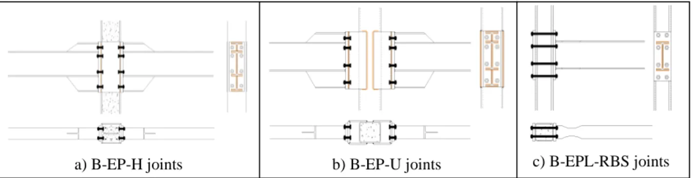
Three bolted end-plate joint configurations were proposed: (1) Bolted hammer head end-plate to wide flange column joint (B-EP-H - Fig. 1): the end-plate welded to the hammer head beam is directly bolted to the flanges of partially-encased wide-flange columns reinforced by lateral plates (pieces 6 in Fig. 1); (2) Bolted hammer head end-plate to RHS column joint with U channel (B-EP-U - Fig. 2): the end-plate welded to the hammer head beam is connected to a concrete-filled tube column through a reverse U channel (pieces 6 in Fig. 2); and (3) Bolted extended end-plate to RHS
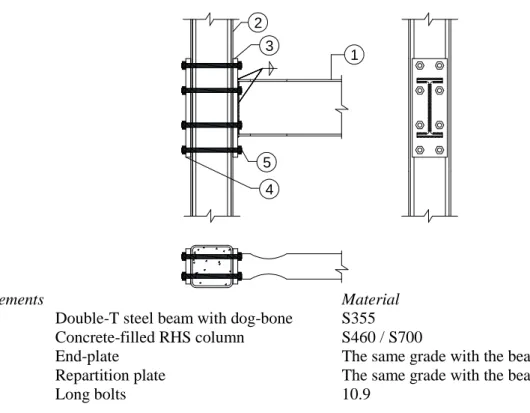
column joint with long bolts and reduced beam section (B-EPL-RBS - Fig. 3): extended end-plates are bolted to concrete-filled tube column using long bolts passing through the column.
The specificity of the proposed solution with the hammer-heads is that the hammer-heads are directly extracted from the same profile than the one used for the beams. Accordingly, no overstrength coefficient needs to be considered for the components associated to these hammer-heads, what leads to a global economy of the proposed solutions as demonstrated in [1] and [2].
2a 2b 3 4 5 6 1
Elements Steel materials
1 Double-T steel beam S355
2a, 2b Top and bottom hammer- heads Extracted from the beam profiles 3 Partially-encased wide-flange column S460 / S700
4 End-plate S355
5 Bolts 10.9
6 Lateral plates Same grade with the column profiles
Fig. 1: B-EP-H joint configuration
1 2a 2b 3 4 5 6a 6b
Elements Steel materials
1 Double-T steel beam S355
2a, 2b Top and bottom hammer-heads Extracted from the beam profile
3 Concrete-filled RHS column S460 / S700
4 End-plate S355
5 Bolts 10.9
6a, 6b Lateral faces and front face of U channel Same grade with column tube
4 1 2 3 5 Elements Material
1 Double-T steel beam with dog-bone S355
2 Concrete-filled RHS column S460 / S700
3 End-plate The same grade with the beam
4 Repartition plate The same grade with the beam
5 Long bolts 10.9
Fig. 3: B-EPL-RBS joint configuration
Within the proposed joint configurations, new components not yet covered by the Eurocodes (in particular, by EN1993-1-8 devoted to joints) and so for which further investigations are required, can be identified:
- the compression zone (and its associated lever arm) of the B-EP-H and B-EP-U joints using hammer head beams;
- the hammer head component in compression/tension for B-EP-H and B-EP-U joints;
- the column flange in bending component with plates welded to the flanges in B-EP-H joints;
- the reverse U channel component in B-EP-U joints and;
- long bolt component with bolt preloading, the latter significantly affecting the prediction of the stiffness of the B-EPL-RBS joints.
These new components were investigated experimentally and analytically in the framework of the previously mentioned HSS-SERF project. Within the present paper, the investigations conducted on the joint configurations using the hammer head solution are briefly summarised. All the details about the conducted investigations can be obtained in [3] (freely available on request to the authors).
2 CONDUCTED EXPERIMENTAL TESTS AND OBTAINED RESULTS
16 large scale specimens were tested within the test campaign conducted at the University of Liege (Table 1): 8 B-EP-H joints and 4 B-EP-U joints. The tested specimens were extracted from reference buildings designed within the HSS-SERF project. HEB320/260 profiles and 300x10/250x10 square hollow sections are used for the columns made of S460/S700 steels while IPE400 with S355 steel grade is used for the beams in all specimens. As the joints have been designed to be full strength, the beams in some specimens are reinforced by welding vertical plates between the flanges to be able to reach the resistance of the joints during the tests and, so, to characterise the behaviour of the joints and to validate the proposed design guidelines for the investigated joint configurations (see Section 3).
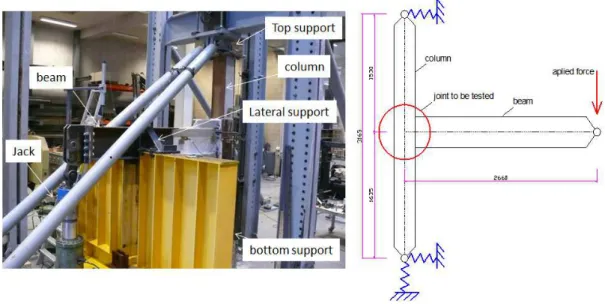
The testing set-up for the beam-to-column joints is presented in Figure 6. Fixed hinges at the bottom and hinges allowing a vertical displacement at the top are used at the column extremities. Possible displacements of the hinges have been anyway recorded during the tests. A vertical load is applied at the free end of the beam introducing a bending moment and a shear force in the joints.
The main test results (i.e. the resistance, the initial stiffness and the failure modes) are presented in Table 2. Additional information such as the coupon tests for the material characterisation, the geometrical measurement, the instrumentation, the bolt tightening, etc. can be found in [3].
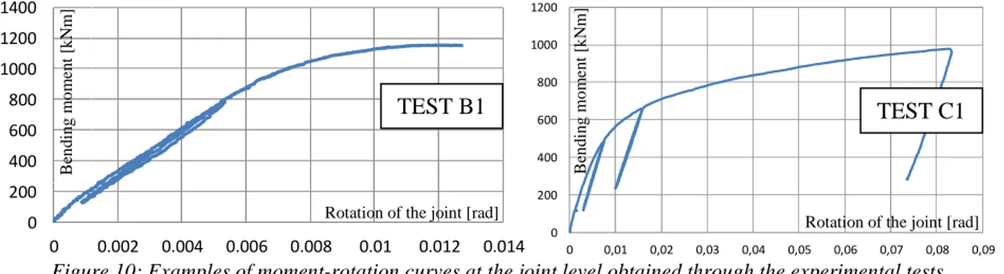
All the moment rotation curves are not reported herein; two examples are reported in Figure 10. All the detailed curves recorded during the tests can be found in [3]. The following remarks can be drawn from the test results: (1) all the joints are full strength ones; (2) B-EP-H joints have a higher stiffness than B-EP-U joints due to the deformability of the reverse U channel in the latters; (3) different failure modes have been observed allowing validating the developments related to the new joint components.
Table 1: description of the tested specimens
N0 Test Joint type Column Details Reinforcement
degree
Loading (a)
1 A1 B-EP-H HEB 320, S460 Figure 4 reinforced Monotonic M+
2 A2 reinforced Monotonic M
-3 A3 not reinforced Monotonic M+
4 A4 not reinforced Cyclic
5 B1 “HEB260”, S690 reinforced Monotonic M+
6 B2 reinforced Monotonic M
-7 B3 not reinforced Monotonic M+
8 B4 not reinforced Cyclic
9 C1 B-EP-U SHS 300x300x12.5, S460 Figure 4 Figure 5 reinforced Monotonic M+ 10 C2 reinforced Monotonic M -13 E1 B-EP-U SHS 250x250x10 S700 Figure 4 Figure 5 reinforced Monotonic M+ 14 E2 reinforced Monotonic M
(a): M+ and M- are hogging and sagging moments, respectively; ANSI/AISC 314-10 protocol is used in the cyclic tests.
250 1 3 5 4 0 0 2 3 5 1 5 1 5 8 0 0 9 0 1 3 7 2 4 6 2 3 7 9 0 180 1 5 0 4 0 0 1 5 0 7 0 0 5 0 1 7 7 2 4 6 1 7 7 5 0 Ø3 3 180 250 Ø3 3 250 1 3 5 4 0 0 2 3 5 1 5 1 5 8 0 0 9 0 1 3 7 2 4 6 2 3 7 9 0 180 Ø3 3 1 5 0 4 0 0 1 5 0 7 0 0 5 0 1 7 7 2 4 6 1 7 7 5 0 180 250 Ø3 3 150 120 140 120
A, B, C specimens E specimens D specimens F specimens
Figure 4: end-plate details
50 240 3 0 0 1 8 1 8 22 50 20 210 2 0 2 5 0 E specimens C specimens
Figure 6: test set-up
Table 2: test results
Test Mmax(a) (kNm)
Stiffness(b) (kNm/rad)
Failure modes
A1 820 193 000 Plastic hinge in the hammer head zone - Figure 7 A2 1187 187 000 Joint failure (bolts + hammer head) - Figure 8
A3 550 210 100 Plastic hinge in the beam - Figure 7
A4 575 182 400 Plastic hinge in the beam - Figure 7
B1 1160 154 500 Joint failure (bolts + hammer head) - Figure 8
B2 (c) 944 177 700
B3 550 214 000 Plastic hinge in the beam - Figure 7
B4 566 144 000 Plastic hinge in the beam - Figure 7
C1 980 82 027 Yield mechanic in reverse U channel - Figure 9 C2 877 80 000 Yield mechanic in reverse U channel - Figure 9 E1 972 70 100 Yield mechanic in reverse U channel - Figure 9 E2 946 68 300 Yield mechanic in reverse U channel - Figure 9 Remarks:
(a): maximal bending moment at the critical section.
(b): in the cyclic tests, the stiffness under hogging moment is reported.
(c): the weld between the beam and the reinforcing plate failed and the test was stopped.
Figure 8: B-EP-H joint – failure in the connection
(4 bolts in the tension zone failed and the hammer head in compression yielded)
Figure 9: failure mode of the B-EP-U joints (reverse U channels yielded)
0 200 400 600 800 1000 1200 1400 0 0.002 0.004 0.006 0.008 0.01 0.012 0.014 0 200 400 600 800 1000 1200 0 0,01 0,02 0,03 0,04 0,05 0,06 0,07 0,08 0,09
Figure 10: Examples of moment-rotation curves at the joint level obtained through the experimental tests
3 DESIGN GUIDLINES
The component method is recommended in EN1993-1.8 for the design of structural joints; Table 3 presents the different components met in the investigated joints and references to Eurocode design rules when available. The new components not yet covered are also identified; for each of them, analytical models for their mechanical characterisation are proposed and validated through comparison to the experimental results in [3].
TEST B1 TEST C1 B en d in g m o m en t [k N m ] B en d in g m o m en t [k N m ]
Rotation of the joint [rad] Rotation of the joint [rad]
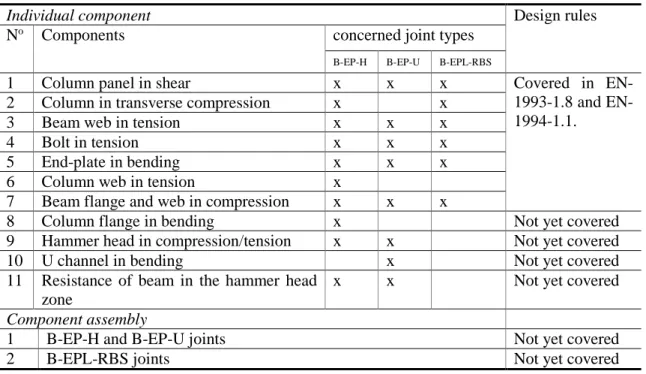
Table 3: identified joint components and availability of design rules
Individual component Design rules
No Components concerned joint types
B-EP-H B-EP-U B-EPL-RBS
1 Column panel in shear x x x Covered in
1993-1.8 and EN-1994-1.1.
2 Column in transverse compression x x
3 Beam web in tension x x x
4 Bolt in tension x x x
5 End-plate in bending x x x
6 Column web in tension x
7 Beam flange and web in compression x x x
8 Column flange in bending x Not yet covered
9 Hammer head in compression/tension x x Not yet covered
10 U channel in bending x Not yet covered
11 Resistance of beam in the hammer head zone
x x Not yet covered
Component assembly
1 B-EP-H and B-EP-U joints Not yet covered
2 B-EPL-RBS joints Not yet covered
4 SUMMARY AND ACKNOWLEDGMENT
Within the present paper, three innovative beam-to-column joint configurations for moment resisting building frames in seismic area are briefly introduced. A test campaign on 16 full-scale specimens was performed, demonstrating the appropriate behaviours of the proposed joint solutions. Also, new joint components, i.e. not yet covered in the design codes, are identified within the proposed joint configurations; analytical design rules for these specific joint components have been developed and validated through comparisons to experimental results.
Using the so-developed analytical models, the proposed joint configurations can be fully characterized (in terms of resistant bending moment and stiffness) using the component method as recommended in the Eurocodes.
The authors are grateful to the European Union for its financial support under the project HSS-SERF RFSR-CT-2009-00024 and to the partners of the project for the fruitful collaboration in the framework of this project.
REFERENCES
[1] Comeliau L., Demonceau J.F., Jaspart J.P. “Innovative bolted beam-to-column joints for seismic resistant building frames”, Connection VII (7th International Workshop on connections in Steel Structures) proceedings published by ECCS (N° 133/2012 – Editors: Dubina, Dan & Grecea, Daniel), pp. 199-208, 2012.
[2] Comeliau L., Demonceau J.F., Jaspart J.P. “Non-dissipative joints in seismic resistant building frames – Bolted beam-to-column joints”, Eurosteel 2011 proceedings, pp. 423-428, 2011.
[3] Hoang V. L., Demonceau J.-F., Jaspart J.-P. “Prequalification tests on bolted beam-to-column joints in moment-resisting dual-steel frames – Deliverable D4”. Deliverable of the RFCS project HSS-SERF (RFSR-CT-2009-00024), freely available on request to the authors, 2014.
EUROSTEEL 2014, September 10-12, 2014, Naples, Italy
BOLTED END-PLATE BEAM-TO-COLUMN JOINTS USING
HAMMER-HEAD BEAMS
Experimental tests and proposal of design guidelines Demonceau Jean-Françoisa, Hoang Van Longa, Jaspart Jean-Pierrea
aArGEnCo Department, University of Liege, Belgium
[email protected]; [email protected]; [email protected]
KEYWORDS: full-strength joints, hammer-head beams, new joint components
ABSTRACT
When considering the capacity design for a frame in seismic area, Eurocode 8 imposes to have full strength beam-to-column joints (with account of possible overstrength effects). This requirement leads generally to uneconomical joint configurations. Within the European RFCS project HSS-SERF - “High Strength Steel in Seismic Resistant Building Frames”, it is intended to propose more economical solutions for such joints using a combination of high strength steel elements for some parts and normal carbon steel for others. As partner of this project, the University of Liege proposed and investigated innovative bolted beam-to-column joints in moment-resisting dual-steel frames susceptible to be loaded by significant seismic actions. Respecting the capacity design approach, the structural joints are full strength ones, taking into account the possible overstrength as recommended in Eurocode 8. One of the specificities of the HSS-SERF project was that the proposed joints were intended to be used in moment resistant dual-steel frames where the beams are made of S355 steel grade while steel grades from S460 to S700 are used for the steel profiles/tubes in the composite columns.
Three bolted plate joint configurations were proposed (Fig. 1): (1) Bolted hammer head end-plate to wide flange column joint (B-EP-H): the end-end-plate welded to the hammer head beam is directly bolted to the flanges of partially-encased wide-flange columns reinforced by lateral plates; (2) Bolted hammer head end-plate to RHS column joint with U channel (B-EP-U): the end-plate welded to the hammer head beam is connected to a concrete-filled tube column through a reverse U channel; and (3) Bolted extended end-plate to RHS column joint with long bolts and reduced beam section (B-EPL-RBS): extended end-plates are bolted to concrete-filled tube column using long bolts passing through the column.
The specificity of the proposed solution with the hammer-heads is that the hammer-heads are directly extracted from the same profile than the one used for the beams. Accordingly, no overstrength coefficient needs to be considered for the components associated to these hammer-heads, what leads to a global economy of the proposed solutions as demonstrated in [1] and [2]. Within the proposed joint configurations, new components not yet covered by the Eurocodes (in particular, by EN1993-1-8 devoted to joints) and so for which further investigations are required, can be identified:
- the compression zone (and its associated lever arm) of the B-EP-H and B-EP-U joints using hammer head beams;
- the hammer head component in compression/tension for B-EP-H and B-EP-U joints;
- the column flange in bending component with plates welded to the flanges in B-EP-H joints;
- the reverse U channel component in B-EP-U joints and;
- long bolt component with bolt preloading, the latter significantly affecting the prediction of the stiffness of the B-EPL-RBS joints.
These new components were investigated experimentally and analytically in the framework of the previously mentioned HSS-SERF project. Within the presented paper, the investigations conducted
about the conducted investigations can be obtained in [3] (freely available on request to the authors).
a) B-EP-H joints b) B-EP-U joints c) B-EPL-RBS joints
Fig. 1: Proposed and investigated joint configurations
CONCLUSIONS
Within the presented paper, three innovative beam-to-column joint configurations for moment resisting building frames in seismic area are briefly introduced. A test campaign on 16 full-scale specimens was performed, demonstrating the appropriate behaviours of the proposed joint solutions. Also, new joint components, i.e. not yet covered in the design codes, are identified within the proposed joint configurations; analytical design rules for these specific joint components have been developed and validated through comparisons to experimental results.
Using the so-developed analytical models, the proposed joint configurations can be fully characterized (in terms of resistant bending moment and stiffness) using the component method as recommended in the Eurocodes.
ACKNOWLEDGMENT
The authors are grateful to the European Union for its financial support under the project HSS-SERF RFSR-CT-2009-00024 and to the partners of the project for the fruitful collaboration in the framework of this project.
REFERENCES
[1] Comeliau L., Demonceau J.F., Jaspart J.P. “Innovative bolted beam-to-column joints for seismic resistant building frames”, Connection VII (7th International Workshop on connections
in Steel Structures) proceedings published by ECCS (N° 133/2012 – Editors: Dubina, Dan & Grecea, Daniel), pp. 199-208, 2012.
[2] Comeliau L., Demonceau J.F., Jaspart J.P. “Non-dissipative joints in seismic resistant building frames – Bolted beam-to-column joints”, Eurosteel 2011 proceedings, pp. 423-428, 2011.
[3] Hoang V. L., Demonceau J.-F., Jaspart J.-P. “Prequalification tests on bolted beam-to-column joints in moment-resisting dual-steel frames – Deliverable D4”. Deliverable of the RFCS project HSS-SERF (RFSR-CT-2009-00024), freely available on request to the authors, 2014.