Thermo-mechanical-metallurgical model to predict geometrical distortions
of rings during cooling phase after ring rolling operations
Silvia Casottoa, Frédéric Pasconb, Anne Marie Habrakenb, Stefania Bruschia a
Dipartimento di Innovazione Meccanica e Gestionale, University of Padova, via Venezia n. 1-35131 Padova, Italy Mechanics and Structure department
bUniversity of Liege, Chemin des Chevreuils n. 1-4000 Liege, Belgium
Abstract
The paper presents a validated numerical model able to predict geometrical distortions of rings during cooling phase after hot ring rolling operations. The model is capable to take into account the effects of all the phenomena resulting from the coupling of thermal, mechanical and metallurgical events. As simulation results strongly depend on the accuracy of input data, physical simulation experiments on real-material samples are developed and carried out to characterize material behaviour during phase transformation.
The numerical model is then validated by an industrial case proving its effectiveness in predicting final ring distortions at room temperature.
Keywords: Steel; Phase transformation; Cooling; Ring rolling
1. Introduction
Ring rolling process is widely used to manufacture annular seamless parts from a bulk pierced billet through a complex sequence of radial or axial-radial rolling operations carried out in hot and warm working conditions. Rolled rings are often critical structural components used in assemblies of most strategic industrial sectors such as automotive and transportation, machine tools, food and chemical, energy, aircraft and aerospace. Ring rolling process allows to obtain rings of close dimensional tolerances and excellent mechanical properties [1-3]. However, the main technological and economical limitation of current hot ring rolling technology is represented by the control of ring geometry during cooling step after rolling. Even for the simplest rings with rectangular section, up to 30% of the metal is wasted due to out-of-roundness, conicity, waviness, etc. These allowances have to be larger for heavily profiled rings, with very high costs for subsequent machining. Great efforts have been spent in the last years to model both experimentally and numerically the deformation step of the process, without paying particular attention on the cooling one. From this standpoint, a tool integrating numerical and experimental techniques, capable to predict rings geometry at room temperature, could represent a great improvement in designing and planning the whole rolling process schedule.
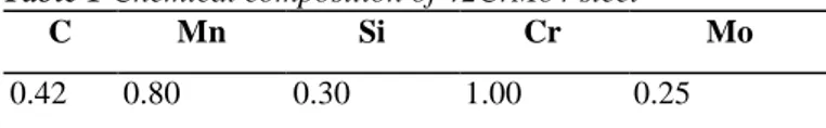
The objective of the current paper is to develop a methodology based on both suitably calibrated numerical and experimental techniques able to predict the final ring geometry and micro structure at room temperature, taking into account thermal shrinkage and micro structure phase transformation phenomena occurring during the cooling sequence. A 2D axi-symmetric numerical model has been set up, using the LAGAMINE finite element code. This model includes all the coupling mechanisms existing among thermal, mechanical and metallurgical events. The calibration of the numerical model to the specific problem has been mainly focused on material properties, including thermo-physical and elasto-plastic properties of each phase, enthalpy and strain of phase transformation, strain of transformation plasticity [4-10]. The reference steel is 42CrMo4, commonly used in ring production; its chemical composition is shown in Table 1.
Table 1 Chemical composition of 42CrMo4 steel
C Mn Si Cr Mo
The paper presents in its first part the numerical model developed to simulate ring cooling and taking into account the effects of all phenomena characterising the process. The developed testing procedures to determine plastic properties and transformation plasticity strain of phases in which austenite may transform during cooling are then shown together with relevant results.
The model is then validated through both temperature and geometrical measurements carried out on the
industrial reference case. Finally, the sensitivity to both material and process parameters on final ring distortions is presented and critically assessed.
2. Numerical modelling
The objective of the numerical model is to predict ring distortions due to cooling from temperatures above austenitization to room temperature by taking into account all the phenomena occurring during cooling. Non symmetric cooling conditions, that are responsible for nonuniform temperature fields, lead to non-simultaneous phase transformations inside the ring section. Geometrical distortions can be modelled only if these cooling conditions and then phase transformations are included in the model.
2.1. Phase transformation model
During cooling, steel rings undergo phase transformations, which occur at different temperatures and times according to several parameters as steel grade and cooling rate. Phase transformation modelling is particularly difficult because of the large number of phenomena that have to be modelled as well as the huge amount of data about material behaviour that are needed; furthermore, most of them are particularly difficult to experimentally measure.
Two different mechanisms of transformation taking place during cooling can be distinguished: diffusive and non-diffusive transformations.
Modelling of diffusive transformations involves the knowledge of the two microscopic phenomena, germination and growth of grains. By extending the models of isothermal transformations to continuous cooling, material final microstructure can be considered as the result of a succession of elementary isothermal transformations, each one being independent from previous thermal history. The validity of this 'additional principle' has been checked by Louin who predicts CCT diagram starting from TTT diagram [12]. This confirms to the possibility of using TTT diagrams instead of CCT diagrams.
The TTT-diagram for 42CrMo4 implemented in the model is shown in Fig. 1. As regards non-diffusive transformations (from austenite to martensite), the formed phase proportion during cooling is governed by the Koistinen-Marburger law:
which only depends on temperature T. The constants Ms (martensite start temperature) and αMa are set equal, respectively, to 331°C and 0.011 K-1 [13].
2.2. Thermal model
The thermal model includes the effects of internal conduction, convection and radiation between ring and surroundings; the heat balance equation is the classical Fourier law
where p is the density, c the specific heat, T the temperature and , in this case, represents the enthalpy of phase transformation. All material thermal properties are characteristics of each phase in which austenite may
transform during cooling and temperature dependent. For phases mixture, equivalent values xeq are computed according to the linear mixture law
where the sum integrates the contribution of all the possible phases in which the steel can be found.
2.3. Mechanical model
The mechanical analysis involves the determination of stresses and strains arising during ring cooling. The model is based on the decomposition of the total strain rate tensor into several contributions
where the five terms are, respectively, elastic, plastic, thermal, transformation and transformation plasticity strain rates. Thermal strain rate is considered proportional to the thermal linear expansion coefficient for each phase. The purely volumetric transformation strain is proportional to the dilatation caused by changes in specific volumes of the phases during transformation. Transformation plasticity strain is the irreversible strain arising during a phase transformation when a stress is applied even below the yield strength of the weaker phase [14]. In relation (4) the strain rate term related to viscoplas-ticity is omitted as the applied stress is less than a quarter of the weaker phase yield strength: it has been demonstrated and reported in the scientific literature that the viscoplastic strain related to creep phenomena in this case may be considered as negligible [14]. In the experiments conducted in Gleeble, this condition is always respected.
The integration of the stress tensor is classically based on a plasticity flow rule associated to von Mises' yield surface with isotropic hardening. A bi-linear elasto-plastic constitutive law has been assumed [15]. Material properties—Young's modulus E(k,T), Poisson's coefficient v(k,T), yield limit σy(k,T), and tangent modulus
Et(k,T)—are characteristics of each phase k and temperature dependent. In the model, equivalent values based on relation (3) are computed according to actual configuration.
3. Calibration of the numerical model
The reliability of a finite element model in reproducing the real distortion during cooling strongly depends on the accuracy of data implemented in the model itself. These data are both related to process conditions (boundary conditions and eventually kinematics) and to material properties (thermo-physical, mechanical and elasto-plastic
properties). While the former can be determined on the basis of the chosen industrial case, the latter can hardly be found in the technical and scientific literature, arising then the need to perform complex laboratory tests to obtain them for each phase in which austenite may transform during cooling.
These data include thermo-physical characteristics, as density, thermal conductivity, specific heat and thermal expansion coefficient, the linear elastic properties, as Young modulus and Poisson's ratio, and the plastic properties, as flow stress data, transformation plasticity coefficient, and parameters related to TTT curves in the presence of applied stress.
Particular attention was paid to thermal expansion coefficient, plastic behaviour, and transformation plasticity of the different phases, as from sensitivity analysis they were recognized to mostly affect the numerical model results in terms of the ring final geometry and microstructure. Physical simulation experiments, briefly described in the following section, were set-up and conducted to determine these parameters for each phase.
4. Experiments
4.1. Flow stress data
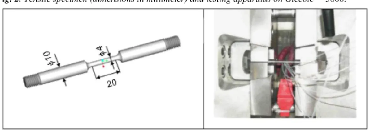
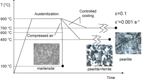
Elasto-plastic behaviour was evaluated for pearlite ferrite+pearlite and metastable austenite phases, the ones that can be attained during air cooling in the reference industrial process; a suitable testing procedure involving tensile tests at different temperatures was developed and set up. All the tensile tests were carried out on the thermo-mechanical simulator Gleeble™ 3800, able to assure an accurate control of all testing parameters during the experiment; temperature is continuously monitored through three thermocouples welded on the specimen surface identifying the specimen gage length. The testing apparatus together with the tensile specimen, designed according to ASTM E8-97 (Standard Test Methods for Tension Testing of Metallic Materials) and ASTM E21-92 (Standard Test Methods for Elevated Temperatures Tension Tests of Metallic Materials) are presented in Fig. 2. Fig. 3 shows the temperature vs. time diagram of the tensile tests to evaluate pearlite, ferrite+pearlite and metastable austenite rheological behaviour. 42CrMo4 samples are heated up to the austenitization temperature, cooled down with a defined cooling rate, held at the testing temperatures until the relevant phase transformation completely occurs and then deformed. The cooling and the testing conditions for each of the considered phases are reported in Table 2.
During the test, the phase transformation starting during cooling and the transformation ending during holding at the testing temperature is continuously monitored through a C-gauge dilatometer. To control the effectiveness of heating and cooling cycles, material microstructure was analysed at room temperature for each testing
conditions; the obtained micro structure s for the different phases are represented in Fig. 3.
All the tensile tests were carried out at constant strain rate equal to 0.001 s-1 and maximum amount of equivalent strain up to 0.1. These values of the process parameters were chosen accordingly to the ones obtained during the preliminary numerical simulations of the cooling step. Each test was repeated three times to assure repeatability of the results.
Fig. 3. Temperature vs. time diagram of tensile tests to determine phases plastic behaviour with relevant
microstructures.
The flow curves of the mixture ferrite + pearlite at the different testing temperatures are shown in Fig. 4. In the ferrite+pearlite region, 42CrMo4 presents a significant sensitivity to temperature; similar results were obtained for material behaviour in fully pearlite and metastable austenite regions. These experimental results prove the strong dependence of the flow strength to the specific phase present in the specimen and the significant material sensitivity to temperature.
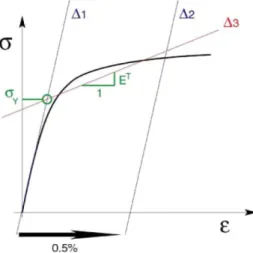
The implementation of the stress-strain curves obtained through physical experiments in the numerical model requires their accurate representation: the elasto-plastic material behaviour is approximated by two segments according to the procedure represented in Fig. 5 [15].
The elastic part of the curve (linear) is identified with the Young modulus (called E) until the yield limit (σy); while the plastic one (obtained experimentally through the above presented laboratory tests) can be replaced by a segment identified by its slope Et (Fig. 6).
Table 2. Experimental plan to determine phases plastic behaviour
Rate of cooling (°C/s) Phase Temperature (°C) -0.1 Pearlite 600 650 700 0.5 Ferrite + perlite 600 650 700 50 Metastable austenite 400 500 600 4.2. Transformation plasticity
Transformation plasticity is an irreversible strain that can be observed when solid state transformation occurs under small external stresses lower than the yield stress of the weaker phase [14]. During ring cooling, the thermal gradient due to non-uniform boundary conditions is responsible for non-simultaneous phase
transformations inside the ring. The presence of internal stresses, that can induce transformation plasticity on the growing phase, can be explained by the non-isotropic transformations, leading to the importance of this
phenomenon during cooling.
From this standpoint, experiments were performed to evaluate transformation plasticity strain, following the procedure represented in Fig. 7. These tests are composed of two different thermo-mechanical cycles: the free dilatometric test and the transformation plasticity test. During both of them, the specimen is heated up to the austenitazion temperature and then cooled down at constant cooling rate according to the desidered metallurgical phase. While during a free dilatometric test the specimen is subjected only to a thermal cycle, on the contrary, in the transformation plasticity one, a load is applied to the specimen just before the starting of the relevant transformation.
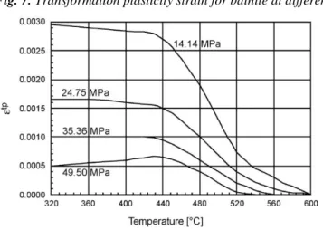
The transformation beginning and its end are monitored through a C-gauge dilatometer, able to measure the tensile specimen total diametral strain with sufficient accuracy. In Table 3, the experimental plans to evaluate transformation plasticity for bainite and ferrite+pearlite phases are reported.
Fig. 4. Ferrite + pearlite plastic behaviour at different temperatures.
Fig. 5. Procedure to implement elasto-plastic curves into the numerical model.
Fig. 7. Transformation plasticity strain for bainite at different levels of loads.
In the case of bainite, the trend of transformation plasticity strain as function of temperature at different levels of applied loads is shown in Fig. 8 [16-18].
Transformation plasticity coefficient is defined as
where σ is the applied stress (uniaxial stress), Z the transformed phase percentage and εtp the final transformation
plasticity strain. With the assumption that the formed phase is about 100%, k coefficient can be calculated as:
Table 4 reports the values of k obtained for bainite and ferrite + pearlite and implemented in the numerical model.
5. Validation of the numerical model
The developed model is applied to the air cooling phase of rings after ring rolling operations. Initial conditions, especially in terms of thermal field, should correspond to the ones at the end of the rolling stage that could be evaluated through 3D F.E. simulation of the process [6-10].
However, a well-calibrated 3D modelling of ring rolling operations requires several efforts in developing the model (especially related to the rolls kinematics) and, moreover, the numerical simulation takes a lot of CPU time. As the aim of this work is to provide a reliable model of the cooling phase capable to evaluate the sensitivity of cooling parameters on the ring distortions, the assumption of uniform thermal and mechanical fields in the rings just after ring rolling was considered.
Table 3. Experimental plan to determine transformation plasticity coefficient
Phase Loading temperature (°C)
Load (MPa)
Bainite 600 0.14.14 24.75 35.36 49.50
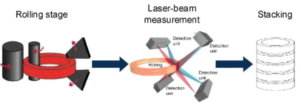
Fig. 8. Laser measuring system.
5.1. Industrial case
To validate the developed numerical model, measurements of both geometry and surface temperature field were carried out on several rings of the reference material just after ring rolling operations during industrial
production. Ring geometry is measured by means of a laser measuring system 180 s after the end of rolling, while, at the same time, optical pyrometers integrated in the system measure surface temperature (the process scheme is shown in Fig. 8).
Dimensions of rings at the exit of the rolling mill are assumed to be equal to the nominal ones: Di= 1085 mm,
De= 1197 mm, H=85 mm without any planarity or conicity defects.
Measurements of rings geometry were also carried out after the complete cooling (at room temperature), with both the laser system and manual calipers, allowing the validation of the laser system itself.
5.2. Simulation of the process
The numerical simulation of the actual industrial process of the cooling phase was performed in two steps: the first one corresponds to cooling from the rolling mill exit to laser-beam measurement while the second one is the successive cooling down to room temperature.
The simulation of the first step requires the knowledge of cooling starting conditions in terms of dimensions and temperature distribution in the ring section; the key problem is the lack of information about the temperature distribution inside the ring, as the only available measurement is the surface temperature. It was assumed the process during first step to be equivalent to the following scheme:
• uniform initial temperature in the ring (T0= 1080 °C, i.e. temperature just after rolling, measured by an optical pyrometer);
• initial geometry equal to nominal ring geometry just after rolling;
• fictive heat transfer coefficients on the four faces of the ring that reproduce the heat transfer due to real manipulations of the ring (rolling and transfer during 180 s on a conveyor to the laser-beam measurement site); • cooling of the ring during an equivalent time that leads to the geometry and to the surface temperature field of the ring as measured by the laser device.
Moreover, it was assumed that, if the geometry and the surface temperature predicted by the numerical model under the imposed boundary conditions correspond to the ones from measurements, then the unknown temperature distribution inside the ring section should correspond to the real one.
The initial conditions of the second step of the numerical simulation correspond then to this computed temperature distribution and to the geometry measured by the laser system measurements. A heat transfer coefficient corresponding to air cooling is then assumed in the cooling simulation. When the ring reaches room temperature, its geometry is checked and compared to the second set of measurements.
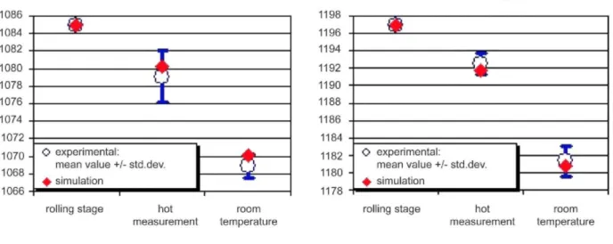
Fig. 9 shows the evolution of internal and external diameters during the process (at the rolling mill exit, at the first measurement and at room temperature). The difference between simulation results and industrial measurements is inferior to the standard deviation of the samples set.
6. Sensitivity analyses
In order to quantify the robustness of the developed numerical model and the possibility to easily adapt it to different operating conditions, sensitivity analyses were performed under different conditions, the aim being to identify the ones that significantly influence the final rings geometry.
Table 4. Calculated transformation plasticity coefficients
Kbainite K ferrite + pear lite
k = 0.86X10⁻⁴MPa-1 k=1.33X10⁻⁴MPa-1
Fig. 9. Comparison in the evolution of internal and external diameters during cooling.
First, the model was tested on rings characterised by different shapes, one being relatively high, but thin and another being thicker, but rather plate-like. In this case, the rings are quenched in a water and polymer solution, providing much faster cooling than in cooling in the air. Fig. 10 illustrates that the thick ring exhibits large distortion, including a rotation that does not occur in the case of the thin ring. Moreover, due to the different cooling conditions in the section, the proportions of phases are quite different, leading to a higher proportion of bainite and martensite for the thinner ring.
Other analyses were performed in order to evaluate the effect of different thermal exchange coefficients with the environment on geometry at room temperature. The same plate and thick rings were quenched in the same water and polymer solution, but considering two different velocities of the bath (0.5 and 0.2 m/s). Heat transfer coefficients in both cases were experimentally determined [19]. Besides the difference in phase distribution, another significant and unexpected result was observed: at higher velocity (0.5 m/s) the section rotates
anticlockwise, while the rotation is clockwise when the heat transfer coefficient decreases with velocity (0.2 m/s; Fig. 11).
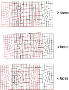
Rings are usually stacked in piles to be quenched: the influence of the ring position in the pile was evaluated by taking into account the possibility that the ring can exhibit two or three faces to the bath, according to its position in the stack. The load effect applied by the top rings in the pile was checked negligible compared to phase transformation effect. Results for the plate and thick ring cooled in polymer bath air are presented considering the three different situations. Fig. 12 clearly shows that in the second case (three faces: the most asymmetric one), distortion is accompanied by a rotation which does not appear in the other two situations.
Fig. 10. Typical distortion of two rings with different shape (displacements are multiplied by 10).
7. Conclusions
A 2D axi-symmetric model based on the finite element method and able to predict geometry of hot ring rolled rings at room temperature after the cooling phase is presented. The FEM model can take into account the effects of phase transformation, phase plasticity and temperature-dependent material properties on final ring distortions. Physical simulation experiments were developed and carried out to determine relevant data about material plastic behaviour during cooling. Based on the simulation results, the effects of both non-uniform cooling conditions and phase transformation were found to cause ring geometrical distortions at room temperature.
Fig. 11. Ring distortions for two different cooling rates (displacements are multiplied by 10).
All the results reported in the paper are relevant to rectangular shaped rings, but the developed methodology is general enough to be applied to profiled rings, where more severe thermal gradients may cause more pronounced geometrical distortions.
Acknowledgements
This cooperative research takes place in the Fifth Framework Programme supported by the European Commission (project reference G1ST-CT-2002-50162). We express our gratitude to the industrial partners Tecnogamma (Italy), CFR (Arcelor Group, Belgium), Forgital (Italy) and Ovako Steel (SKF Group, Sweden). Parts of this paper are extracted from RW9813793 project supported by Walloon Region. As Research Associate of National Fund for Scientific Research (Belgium), A.M. Habraken thanks this Belgian research fund for its support.
References
[1] M.S. Joun, J.H. Chung, R. Shivpuri, An axisymmetric forging approach to preform design in ring rolling using a rigid-viscoplastic element method, International Journal of Machine Tools & Manufacture 38 (1998) 1183-1191.
[2] E. Doege, A. Aboutour, Simulation of ring rolling process, Proceedings in Advanced Technology of Plasticity, vol. II 1987 pp. 817-824.
[3] K. Davey, M.J. Ward, The practicalities of ring rolling simulation for profiled rings, Journal of Materials Processing Technology 5970 (2002) 1-7.
[4] A.M.S. Hamouda, S. Sulaiman, C.K. Lau, Finite element analysis on the effect of workpiece geometry on the quenching of ST50 steel, Journal of Materials Processing Technology 119 (2001) 354-360.
[5] C. Heming, F. Jiang, W. Honggang, Estimation of the mechanical properties of a 42CrMo steel cylinder with phase transformation during quenching, Journal of Materials Processing Technology 63 (1997) 568-572.
[6] S. Claudinon, P. Lamesle, J.J. Orteu, R. Fortunier, Continuous in situ measurement of quenching distortions using computer vision, Journal of Materials Processing Technology 122 (2002) 69-81.
[7] C.C. Liu, X.J. Xu, Z. Liu, A FEM modeling of quenching and tempering and its application in industrial engineering, Finite Elements in Analysis and Design 2003;.
[8] Y.D. Huang, L. Froyen, Important factors to obtain homogeneous and ultrafine ferrite-pearlite microstructure in low carbon steel, Journal of Materials Processing Technology 124 (2002) 216-226.
[9] H.C. Gur, A.E. Tekkaya, Numerical investigation of non-homogeneous plastic deformation in quenching process, Materials Science and Engineering A319-321 (2001) 164-169.
[10] P.F. Bariani, S. Bruschi, S. Casotto, Integrating numerical and experimental techniques to determine geometrical distortions of rings during cooling phase in hot rolling operations, Proceedings of 6th AITEM Conference, Gaeta 2003;.
[11] F. Wever, A. Rose, W. Peter, W. Strassburg, L. Rademacher, Atlas zűr Wärmebehandlung der Stälhe, Verlag Stalheisen M.B.H., Dűsseldorf, 1958.
[12] J.C. Louin, Effet d'hétérogénéités de teneur en carbone sur les cinétiques de transformation de phases et sur la genèse des contraintes internes lors due refroidissement d'acier, Inst. Nat. Polytechnique de Lorraine (France), 2003, PhD Thesis.
[13] A.S. Judlin-Denis, Modélisation des interactions contrainte-transformation de phase et calcul par éléments finis de la génère des contraintes internes au cours de la trempe des aciers, Inst. Nat. Polytechnique de Lorraine (France), 1987, PhD thesis.
[14] L. Taleb, N. Cavallo, F. Waeckel, Experimental analysis of transformation plasticity, Intenational Journal of Plasticity 17 (2001) 1-20.
[15] A.M. Habraken, M. Bourdouxhe, Coupled thermo-mechanical-metallurgical analysis during the cooling process of steel piece, European Journal of Mechanics A/Solids 11 (3) (1992) 381-402.
[16] G.I. Rees, P.H. Shipway, Modelling transformation plasticity during the growth of bainite under stress, Materials Science and Engineering A223 (1997) 168-178.
[17] S. Petit-Grostabussiat, L. Tleb, J.F. Jullien, Experimental results on classical plasticity of steels subjected to structural transformation, International Journal of Plasticity 20 (2003) 1371-1386.
[18] M. Coret, S. Calloch, A. Combescure, Experimental study of the phase transformation plasticity of 16MND5 low carbon steel under multiaxial loading, International Journal of Plasticity 2002; 1707-1727.
![Fig. 1. TTT-diagram of 42CrMo4 steel [11].](https://thumb-eu.123doks.com/thumbv2/123doknet/5896053.144246/2.893.119.601.780.1103/fig-ttt-diagram-of-crmo-steel.webp)