HAL Id: hal-00276359
https://hal.archives-ouvertes.fr/hal-00276359
Submitted on 29 Apr 2008
HAL is a multi-disciplinary open access
archive for the deposit and dissemination of sci-entific research documents, whether they are pub-lished or not. The documents may come from teaching and research institutions in France or abroad, or from public or private research centers.
L’archive ouverte pluridisciplinaire HAL, est destinée au dépôt et à la diffusion de documents scientifiques de niveau recherche, publiés ou non, émanant des établissements d’enseignement et de recherche français ou étrangers, des laboratoires publics ou privés.
Characterization and Locking of Optical
Mini-Resonators for Microwave Sources Stabilization
Pierre-Henri Merrer, Pierre Lacroix, Houda Brahimi, Sophie Bonnefont,
Olivier Llopis, Laura Ghisa, Yannick Dumeige, Patrice Féron, Gilles Cibiel
To cite this version:
Pierre-Henri Merrer, Pierre Lacroix, Houda Brahimi, Sophie Bonnefont, Olivier Llopis, et al.. Char-acterization and Locking of Optical Mini-Resonators for Microwave Sources Stabilization. European Frequency and Time Forum, Apr 2008, Toulouse, France. paper n° 105. �hal-00276359�
Characterization and Locking of Optical
Mini-Resonators for Microwave Sources Stabilization
Pierre-Henri Merrer, LAAS-CNRS and Toulouse University, Toulouse, FRANCE Pierre Lacroix, LAAS-CNRS and Toulouse University, Toulouse, FRANCE Houda Brahimi, LAAS-CNRS and Toulouse University, Toulouse, FRANCE Sophie Bonnefont, LAAS-CNRS and Toulouse University, Toulouse, FRANCE
Olivier Llopis, LAAS-CNRS and Toulouse University, Toulouse, FRANCE Laura Ghisa, ENSSAT-FOTON (CNRS-UMR 6082), Lannion, FRANCE Yannick Dumeige, ENSSAT-FOTON (CNRS-UMR 6082), Lannion, FRANCE
Patrice Féron, ENSSAT-FOTON (CNRS-UMR 6082), Lannion, FRANCE Gilles Cibiel, CNES, toulouse, FRANCE
BIOGRAPHY
Pierre-Henri Merrer received the Master’s degree in Photonics and Optical Telecommunications from ENSSAT (Lannion, France), in 2005. He is currently Ph.D. student in LAAS (Laboratory for Analysis and Architecture of Systems), in the research group MOST (microwaves and opto-microwaves for telecom- munication systems) and works on microwave-optical systems and high Q optical resonator.
INTRODUCTION
Investigations towards a resonator featuring a high quality factor in a reduced volume are a very important and interesting point in the microwave field. Such resonator could be used for time-frequency applications. In particular, it could be an alternative solution to the ultra-stable BAW oscillator for space applications. Other applications may also concern radars or telemetry with very high sensitivity, and telecommunication applications. The resonators used in these applications are often too big and it is important to reduce their size without loosing the quality factor, especially in embedded systems. Today high spectral purity sources are dielectric resonator oscillators, which includes ceramic and monocristalline resonators (mainly sapphire). The main problem with sapphire resonator is its size and the main problem with ceramic resonator is the Q.f parameter
which remains below around 1014 (f in Hz). Finally, the
technologies for high spectral purity microwave sources are reaching their limits when the goal is to get simultaneously high performance in term of phase noise, small size (integration) and high frequency operation. Therefore, an original idea is to transpose the microwave wavelength in the optics field and to trap the signal in an optical resonator. Contrary to the conventional microwave resonators, the optical-microwave resonator features an equivalent Q at microwave frequencies which increases as the microwave frequency increase. The first microwave source using an optical frequency reference
has been proposed in 1994 [1]. This source was based on an optical delay line which features a typical equivalent
microwave quality factor in the range of Q ~ 106 at
10 GHz [2]. It is today a well known technique, already commercialized. The main problem with these optical-electronic oscillators (OEO) is their size and their sensitivity to temperature changes. A recently proposed alternative approach [3] replaces the optical delay line by an optical mini-resonator, which allows an important decrease in size while keeping a relatively high Q factor.
Depending on the type of optical resonators (SiO2
mini-sphere, or monocrystalline disk) their optical quality
factor can reach values from 108 to 1010, which results in
an equivalent Q from 104 to 106 at 20 GHz.
HIGH Q OPTICAL MINI-RESONATORS
The first step in this study has been to develop a measurement protocol in order to obtain the optical quality factor of the mini-resonators. Two measurement benches have been set-up to characterize various type of high Q optical mini-resonator: one based on the technique of cavity ring down in ENSSAT-FOTON, and the other one based on wavelength scan in LAAS-CNRS.
The LAAS-CNRS mini-resonator measurement bench has been described in details elsewhere [4]. It uses piezoelectric components which allow the control of the resonator coupling with a submicron scale precision in 3D displacement. Moreover, it protected from air flow and dust which could modify the coupling value and quality factor resonator value.
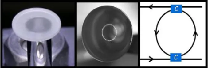
Figure 1: Quartz 7 mm minidisc (left), silica 3 mm minisphere (middle), and fiber ring resonator (right).
The resonators which have been characterized in this
study are SiO2 micro- and mini-spheres, a polished disk
of monocristalline material and a fiber ring resonator (figure 1).
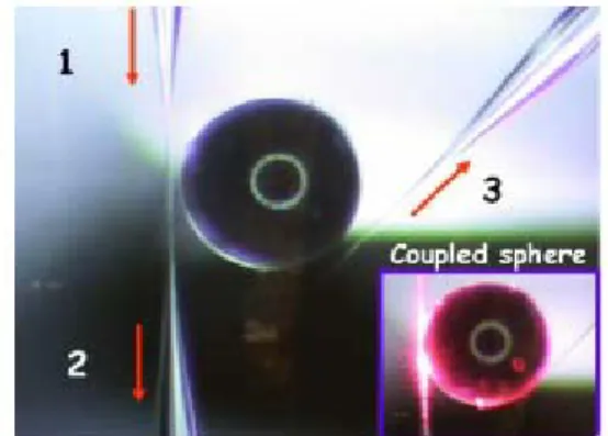
Figure 2: Microsphere of 400 µm diameter with a tapered and a half-tapered fiber coupling configuration. The laser is transmitted through
the sphere from (1) to (3) and the uncoupled light can be measured in (2). Inset: microsphere coupled to a visible laser.
SiO2 microspheres, realised in ENSSAT-FOTON, are
formed by fusion and surface tension which confers to them a very good surface state. This type of resonator presents a very high Q, but the quality factor decreases if they are not isolated from humidity [5]. Experimentally, a
Q factor larger than 109 has been demonstrated [6]. This Q factor is however limited by light absorption in silica.
The diameters of the silica spheres realised are in the order of 400 µm, featuring therefore a mode spacing between the main modes of 160 GHz [4]. In figure 2, the way these resonators are coupled to optical fibers is shown.
In order to get a smaller mode spacing between the main modes, silica spheres with a larger diameter have been
realized using a different technique based on a CO2 laser.
The size of these spheres is 3.3 mm in diameter, which leads to a mode spacing of 20 GHz. It is also coupled on the input side to a tapered fiber and on the output side, to an half tapered fiber. This coupling technique is efficient, but it is sensitive to vibrations.
Figure 3: Angle polished fiber (right) and image of its surface quality (left) with SEM.
In addition to the well-known prism coupler, another technique which has been investigated is the one of the angle polished fiber. The results obtained currently with this technique are not satisfactory, but the improvement of the surface quality of these angle polished fibers is in
progress and the technique will be soon effective and more robust than tapered fiber. It is important especially in embedded systems. Such an angle polished fiber is show figure 3, together with SEM (Scanning Electron Microscopy) image of its polished surface.
In figure 4, whispering gallery mode (WGM) resonance of the 3.3 mm silica sphere is examined using the method of wavelength scan. The sphere is coupled using a bi-conic taper (waist < 2 µm). The WGM resonance is scanned by tuning over 6.5 GHz around λ = 1550 nm of a 100 kHz linewidth laser. We obtain a full width at half
maximum (FWHM) of ΔfFWHM = 830 kHz, which
corresponds to a quality factor of Q = 2.108.
-4 -3 -2 -1 0 1 2 3 4 0,5 0,6 0,7 0,8 0,9 1,0 FWHM = 830kHz => Q~2*108 Transmission (u.a ) Frequency (MHz) Δf = 830 KHz
Figure 4: Experimental data (black curve) of the transmission response of 3.3 mm silica sphere with the method of wavelength scan. The red
curve is the Lorentzian function approximation of the experimental curve.
An alternative to fused silica resonators is to use a monocristalline material featuring very low optical losses. This approach theoretically allows higher Q factors, and the resonator is less sensitive to humidity absorption. However, the condition to reach high Q factors is to
realize a good curved surface state on these resonators.A
quartz disk resonator of 7 mm in diameter has been realized, corresponding to a mode spacing of 8 GHz.
15 20 25 30 35 -56 -54 -52 -50 -48 -46 -44 -42 -40 -38 -36 ~ 8 G H z ~20°C ~2 nm ~ 250 G H z Int en si ty Ou tput ( dB m )
D FB laser tem perature (°C)
In ten sity Ou tp ut (d Bm) DFB laser Temperature (°C)
Figure 5: Experimental data of the transmission response of Quartz minidisc with wavelength scan with DFB laser. The minidisc is excited
with the same coupling configuration described in the figure 2.
Figure 5 shows the main resonances of this resonator every 8 GHz on a 250 GHz bandwidth. To perform this measurement, a temperature tuned DFB laser has been used. However, the spectral linewidth of this laser is larger than the resonator half bandwidth. It is thus
impossible to estimate the optical quality factor for this resonator. This technique using the DFB laser allows to have only the resonances chart on a wide frequency range.
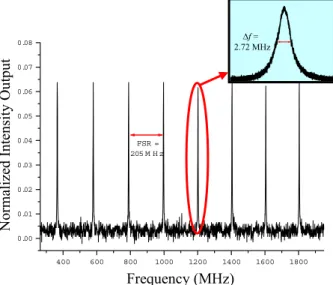
The last resonator which has been studied is a fiber ring resonator. It is formed by two optical waveguides coupled to a single fiber ring resonator. The first optical fiber loop realized has a total length close to 1 m, which leads to mode spacing of 205 MHz. 400 600 800 1000 1200 1400 1600 1800 0.00 0.01 0.02 0.03 0.04 0.05 0.06 0.07 0.08 FSR = 205 M H z
Figure 6: Experimental data of the intensity response of for fiber ring resonator with the method of wavelength scan. The resonances are scanned by tuning the laser temperature around λ = 1550 nm of a 1 kHz
linewidth laser.
This type of resonator has an optical quality factor close to the one of the mini-resonators studied. Of course, the size of this resonator is larger than the 3D resonators, but it is a good test system to exhibit the problems of mini-resonator. For example, the dynamical thermal behaviour of an optical resonator and the hysteretic wavelength response have been observed with this resonator (see next paragraph). Moreover, its 2D shape makes its integration easy in a system where the equipments are assembled on a relatively large planar substrate (at least 10 cm x 10 cm). In figure 6, the 205 MHz spacing between the modes and the measurement of the Q factor are examined using the method of wavelength scan.
Figure 7: Experimental data (red curve) and theoretical model (blue curve) of the transmission response of fiber ring resonator with the
method of cavity ring down
We obtain ΔfFWHM = 2.72 MHz which corresponds to a
quality factor of Q = 7.1.107. Figure 7 shows an example
of cavity ring down measurement realised at ENSSAT-FOTON of the fiber ring resonator. By direct treatment of the exponential decay of the maxima [7], we deduce
Q = 7.5.107.
RESONATOR DYNAMICAL THERMAL-BEHAVIOR AND FEEDBACK CONTROL
It is difficult to get an efficient resonator coupling, because of the mode shift with temperature when the light in induced in the resonator. This is clearly seen in figure 8, which corresponds a thermal resonant-drift of optical fiber loop during wavelength scan. During the downscan, the resonance is narrowed. The reason for this behavior is that during the down wavelength scan the thermal effect is opposed to the laser shift. While the resonator frequency follows the laser frequency during the up wavelength scan. In the case, the resonance is expanded because of self heating.
Δf = 2.72 MHz N ormalized In te ns ity Ou tpu t 1.0 1.5 2.0 2.5 3.0 3.5 4.0 4.5 0.50 0.55 0.60 0.65 0.70 0.75 0.80 0.85 0.90 Tim e (s) Int en s it y Tr an s m issi on (mV ) In ten sity Tran smissio n (mV) Frequency (MHz) Times (s)
Figure 8: Dynamical thermal behaviour of fiber ring resonator during the up wavelength scan (blue curve) and during the down wavelength
scan (red curve).
The solution to achieve maximum loading of the resonator is to lock the laser onto the resonator frequency. This has been realized using a Pound-Drever feedback loop [8, 9]. A schematic of the experimental setup is shown in figure 9. The validity of this approach has been verified experimentally on an optical fiber ring resonator.
In ten sity Tran smissio n (mV) Times (µs) LASER LOCAL OSCILLATOR (LO) MIXER PHASE SHIFTER φ EOM Î PHOTODETECTOR DC RF PID OSCILLOSCOPE PIEZO DRIVER 1 2 LASER LASER LOCAL OSCILLATOR (LO) MIXER PHASE SHIFTER φ EOM Î PHOTODETECTOR DC RFDC RF PID OSCILLOSCOPE PIEZO DRIVER 1 2 1 2
Figure 9: Detailed configuration of a Pound-Drever feedback loop with the fiber ring resonator.
When the Pound-Drever loop is closed, the resonator transmission is locked to its maximum value, ie the laser is locked onto the resonance. If the controller gain and
integration time of the proportional integrator differentiator (PID) have been correctly chosen, the correction maintains the laser locked onto the resonance for a long time [10]. Figure 10 shows the resonator transmission versus time, when the feedback Pound-Drever loop is closed or not.
Figure 10: Experimental data of the intensity response of fiber ring resonator showing the laser locked onto the resonance (red) in
comparison with Pound-Drever unlocked cavity (black).
As soon as the laser is locked onto the resonance, it is possible to use the system for microwave applications. For example, the optical fiber ring resonator can play the role of a microwave filter. For this, a Mach-zehnder modulator (MZM) must be added in the experimental setup described in figure 11.
Figure 11: Detailed configuration of a microwave filter with the optical fiber ring resonator.
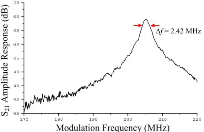
When the cavity transmission is locked to its maximum value, the RF or microwave modulation signal can be filtered by the optical resonator. The modulation goes through the two lateral side modes, and is filtered by these modes. Thus the optical transfer function is brought back in the microwave range. A high quality RF resonance is observed on the network analyser, featuring a spectral width of 2.4 MHz (figure 12).
Such a spectral width is interesting for microwave applications, and particularly in the upper microwave range (above 20 GHz) or in the millimetre wave range. As an example, it corresponds to a loaded Q factor of 10000 at 24 GHz, which is a value which cannot be obtained with conventional ceramic dielectric resonator. Of course, our goal is to replace the fiber loop resonator by the mini-resonators. However, the results obtained with the fiber loop resonator are already interesting for applications, and the laser frequency stabilization approach studied with this resonator can easily be applied
to the case of the miniresonator.
170 180 190 200 210 220 -55 -50 -45 -40 -35 -30 -25 -20 -15
Figure 12: Measurement data of the amplitude response of S21 for the
S21 Am pl itude R espo nse ( dB Modulation Frequency (MHz)
fiber ring resonator.
The next step will be to realize an optical-microwave
Figure 13: Configuration of optical-microwave oscillator with the
The main noise co or due
rization approach dedicated to
ank CNES, TSA and ANR al Research Agency) for financial support.
oscillator with this resonator, such as the one depicted in figure 13. This oscillator should be competitive with classical microwave oscillators, because the additive phase noise of optical links is relatively weak [11].
different types of miniresonator.
ntribution is the white noise flo
to the losses in the electrical to optical and optical to electric conversion, but the additive optical 1/f noise is surprisingly low [11]. If realized in the millimetre wave range, these oscillators will take benefit of the ultra high
Q factor of the optical resonator and will thus exhibit an
exceptional spectral purity.
CONCLUSION
In this paper, a characte
microwave optical miniresonators and optical resonant fiber loops has been described.
This approach uses a high precision set up with nanometre scale control of the coupling factor (case of miniresonator) and a laser stabilization technique based on a Pound-Drever feedback loop.
The interest of the approach is demonstrated using a fiber loop resonator, with which a narrow band RF or microwave filter has been realized.
CKNOWLEDGEMENTS A
The author would like to th (Nation ) Δf = 2.42 MHz 0 2 4 6 8 10 12 14 0.00 0.01 0.02 0.03 0.04 0.05 0.06 0.07 N ormalized In te ns ity Ou tpu t Times (s) To ma ximum r esona tor tr an smission Locked Unlocked Pout O/E E/O φ Pout O/E E/O φ Mode stabilization ARV Mode stabilization MZM Port 2 Port 1 LASER LOCAL OSCILLATOR (LO) MIXER PHASE SHIFTER φ EOM Î DC RF PID OSCILLOSCOPE PIEZO DRIVER 1 2 ARV PHOTODETECTOR Port 2 Port 1 MZM LASER LOCAL OSCILLATOR (LO) MIXER PHASE SHIFTER φ EOM Î DC RF PIEZO DRIVER 1 2 PID OSCILLOSCOPE PHOTODETECTOR
REFERENCES
[1] Yao X.S., and Maleki L., “High frequency optical
subcarrier generator”, Electronics Letters, 30 (18),
[2]
illator – a ten year anniversary
[3] modes-Part II: [4] l G., “A [5] [6] h ments of [7] ten million [8]
ave Oscillators”, Rev. Sci. Instrum., 17(11),
[9]
requency Stabilization Using an
[10]
and Vahala K., “Feedback control of
[11]
e Microwave
pp.1525-1526, 1994.
Yao X.S., Maleki L., and Eliyahu D., “Progress in
the optoelectronic osc
review”, IEEE Microwave Theory and Tech. Symp.
Digest, 1, pp. 287-290, 2004.
Ilchenko V.S. and Matsko A.B., “Optical resonators
with whispering-gallery
Applications”, IEEE Journal of selected topics in
quantum electronics, 12 (1), pp.15-32, 2006.
Constant S. B., Merrer P.H., Onillon B., Dollat X., Llopis O., Féron P., Dummeige Y., and Cibie
characterisation bench to analyse various types of optical WGM resonators for high spectral purity microwave sources applications”, IEEE Int.
Frequency Control Symposium, pp. 519-527, 2006. Gorodetsky M.L., Savchenkov A.A., and Ilchenko V.S., “Ultimate Q of optical microsphere
resonators”, Optics Lett. 21, pp. 453, 1996.
Vernooy D.W., Ilchenko V.S., Mabuc i H., Streed E.W., and Kimble H.J., “High-Q measure
fused-silica microspheres in the near infrared”,
Optics Lett., 23(4), pp. 247-249, 1998.
Savchenkov A. A., Matsko A. B., Ilchenko V. S., and Maleki L., “Optical resonators with
finesse” Optics express, 15(11), pp.6768-6773,
2007.
Pound R.V., “Electronic Frequency Stabilization of
Microw
pp. 490-505, 1946.
Drever R.W. P., Hall J. L., Kowalski F. V. et al., “Laser Phase and F
Optical-Resonator”, Appl. Phys. B., 31(2), pp.
97-105, 1983.
Carmon T., Kippenberg T., Yang L., Rokhsari H., Spillane S.,
ultra-high-Q microcavities: application to micro-Raman lasers and microparametric oscillators”, Opt.
Express, 13(9), pp. 3558-3566, 2005.
Onillon B., Constant S., and Llopis O., “Optical
Links for Ultra Low Phase Nois
Oscillators Measurement”, IEEE Int. Frequency