HAL Id: hal-01160827
https://hal.archives-ouvertes.fr/hal-01160827
Submitted on 25 Jun 2019
HAL is a multi-disciplinary open access
archive for the deposit and dissemination of
sci-entific research documents, whether they are
pub-lished or not. The documents may come from
teaching and research institutions in France or
abroad, or from public or private research centers.
L’archive ouverte pluridisciplinaire HAL, est
destinée au dépôt et à la diffusion de documents
scientifiques de niveau recherche, publiés ou non,
émanant des établissements d’enseignement et de
recherche français ou étrangers, des laboratoires
publics ou privés.
System for Balancing of 4-DOF Robot Manipulators
with Variable Payloads
Sébastien Briot, Vigen Arakelian
To cite this version:
Sébastien Briot, Vigen Arakelian. A New Energy-free Gravity-compensation Adaptive System for
Balancing of 4-DOF Robot Manipulators with Variable Payloads. The Fourteenth International
Fed-eration for the Promotion of Mechanism and Machine Science World Congress (2015 IFToMM World
Congress), Oct 2015, Taipei, Taiwan. �hal-01160827�
A New Energy-free Gravity-compensation Adaptive System for Balancing of
4-DOF Robot Manipulators with Variable Payloads
S. Briot∗and V. Arakelian†
Institut de Recherche en Communications et Cybern´etique de Nantes (IRCCyN) UMR CNRS 6597, Nantes, France
Abstract— In most of gravity balancing approaches de-voted to robot manipulators, the gravity compensation is carried out for cancelling of the static efforts due to robot element masses, as well as a fixed payload. When the pay-load is variable, i.e. if for each cycle of the robot opera-tion it is different, the known compensaopera-tion techniques are not efficient. Some solutions permitting to compensate the gravity effects of variable payloads have been developed. However, they have similar drawbacks. To adapt the robot to the changing payload it is necessary: i) to increase the number of actuators and ii) to bring energy inside the sys-tem, i.e. the adaption technique is not energy efficient.
This paper deals with a new gravity-compensation sys-tem for cancellation of the static loads of the changing pay-load. It is shown that the adaption to a new manipulated payload does not need to bring energy inside the system, i.e. the adaption technique is energy efficient. Simulations of the suggested mechanism by using ADAMS software are performed and show the efficiency of the proposed solution.
Keywords: robot manipulators, gravity compensation, static bal-ancing, variable payload
I. Introduction
Any mechanism is statically balanced (also denoted as gravity-balanced) if its potential energy is constant for all possible configurations. With regard to the static balancing in robotics, this term differs from the first definition because in this case, the aim of the balancing is the minimization or cancellation of input efforts of a mechanical system by means of gravitational force balancing. This means that the mechanism is statically stable for any configuration; i.e., zero actuator input efforts due to the static loads are re-quired.
For static balancing of robot mechanisms, different ap-proaches and solutions have been developed and docu-mented. The balancing schemes for robotic systems can be systematized by taking into account the nature of the compensation force:
• with counterweights (group A): this is a classical ap-proach which consists in adding counterweights in order
∗[email protected] †[email protected]
to keep the total centre of mass of moving links station-ary [1–9].
• with spring (group B): the approaches developed in this group are based on the use of either zero-free length springs or non zero-free length springs [10–25].
• with a complementary actuator which can be a pneu-matic or hydraulic cylinder, electromagnetic device, etc. (group C): In this case, a pneumatic or hydraulic cylinder is connected with some manipulator links [26–29] or directly with the moving platform [30]. There are also some ap-proaches based on special counterweights, which are fluid reservoirs. Continuous gravity compensation is achieved by the pumping of fluid from the first reservoir-counterweight to the second.
The main drawbacks of the mentioned solutions when applied to robotics is that they ensure the gravity balancing of the robot for a given gravity load. However, when this load is varying (for example, during a palletizing task), they cannot ensure the cancellation of the gravity effects due to change of the payload. To overcome this difficulty, a few solutions have been proposed. The most resourceful ones are listed below:
• The use of active counterweights, such as in [28, 31] where the position of the counterweights on the balanced links varies and is modified through the use of additional actuators. This leads to the increase of the number of actu-ators and, obviously, to the development of a more complex controller.
• In [32], a variable gravity compensation mechanism is proposed. It uses two types of linear springs and changes the equilibrium position of one of these. This also leads to the considerable increase of the number of actuators and the achievement of more complex controllers.
• The gravity compensation technique developed in [33– 35] uses remote counterweights connected to the robot via a hydraulic transmission. As it has been shown in [34] the built prototype of the 7-degrees-of-freedom (DOF) robot is able to adapt its balancing counterweights to a payload of up to 10 kg, which was a maximal payload for the tested prototype. The main drawbacks of this technique is the use of hydraulic power systems (while the robot energy is pro-vided by electricity) and the increase of the system foot-print.
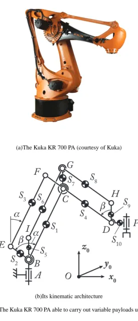
fol-(a)The Kuka KR 700 PA (courtesy of Kuka)
A
B
C
D
P
E
F
G
H
I
x0
z0
y0
O
α
β
β
α
S
1S
2S
3S
4S
6S
8S
7S
10S
5S
9(b)Its kinematic architecture
Fig. 1. The Kuka KR 700 PA able to carry out variable payloads up to 700 kg.
lowing. When the payload is changing from a massm1to a massm2, there is a change of potential energy in the system equal to∆V = gz(m2− m1) (where g is the gravitational constant and z the altitude at which the load is changed).
Therefore, ifm2> m1, energy must be brought in the sys-tem to be able to adapt and to compensate the new payload. Ifm2 < m1, if the robot was ideal, it should be able to stock the non necessary energy in capacitors or batteries. However, even if most robot actuators are now equipped with four-quadrant amplifiers which are able to stock addi-tional energy in capacitors, as the stocking performance of capacitors is limited, many energy is still dissipated (under the form of heat) to avoid the overload of the capacitors.
Thus, all existing adaptive gravity-compensation systems of robots are not energy efficient. Please note that the en-ergy efficiency of machines (but not only machines) in EU will becomes soon an important research problem as the
ac-tual european policy is to target a decrease of 20% of con-sumed energy for 2020 (and 40% for 2030). In the present paper, taking into account that many robots used for the pick-and-place operations of heavy devices (such as palleti-zation operations) are 4-DOF industrial robots such as the Kuka KR 700 PA presented in Fig. 1, we present an active balancing system able to compensate the gravity effects of a variable payload without the need of bringing additional energy in the whole robotic system. In the Section II, we show that it is possible to fully balance the gravity effects on the manipulator. Then, in Section III, we present the adaptive-gravity balancing system able to compensate the gravity effect of variable payloads. In Section IV, numer-ical validations made with the software ADAMS are per-formed. Finally, in Section V, conclusions are drawn.
It should be noticed that a patent on the proposed balanc-ing system is currently pendbalanc-ing [36].
II. Gravity-balacing of the manipulator only
A. Description of the robot architecture to balance without payload
Let us consider the kinematic architecture of the
4-DOF industrial robot depicted at Fig. 1(b). This
architec-ture, made of revolute (R) joints only, allows the robot to perform Sch¨onflies motions (i.e. its effector located at point
P is able to carry out three translations along the base frame
axes x0, y0and z0and one rotation around z0). These four DOF are controlled through the actuation of motors linked
to the R joints located at pointsA, B (two R joints are
lo-cated at this point, one controlling the angleα, the second
one the angleβ) and P .
The links attached to the R joints located at: • B, C, F and E,
• B, C, G and I, • C, D, H and G,
form articulated planar parallelograms (also denoted asΠ
joints). TheΠ joints BCGI and CDHG ensure the axis of
the R joints located at pointP to be always vertical, while
theΠ joint BCF E allows for remoting the actuation of the
linkCD as close as possible to the base.
In the following of the paper, the gravity field g is equal to g= [0 0 − g]T (g > 0) and is directed along z
0. More-over, we denote as:
• Sithe centre of mass of the linki, • mithe mass of the linki,
• ℓQRthe length between two arbitrary pointsQ and R, • zQthe position along the z0axis of anarbitrary pointQ. B. Computation of the gravitational potential energy
The robot (without payload) gravitational potential en-ergyV is given by:
V = g
10
X
i=1
in which zS1 = zB+ ℓBS1cos α (2) zS2 = zB+ ℓBS2cos β (3) zS3 = zB+ ℓBEcos β + ℓES3cos α (4) zS4 = zB+ ℓBCcos α − ℓCS4cos β (5) zS5 = constant (6) zS6 = zI+ ℓIS6cos α (7) zS7 = zB+ ℓBCcos α + lCS7 (8) zS8 = zB+ ℓBCcos α + lCG− ℓGS8cos β (9) zS9 = zB+ ℓBCcos α − ℓCDcos β + ℓDS9 (10) zS10 = zB+ ℓBCcos α − ℓCDcos β (11)
taking into account thatzBandzIhave constant values. Introducing (2)–(11) into (1), and simplifying, we obtain
V = a cos α + b cos β + c (12) with a =g(m1ℓBS1+ m3ℓES3+ m4ℓBC+ m6ℓIS6) + g(m7ℓBC+ m8ℓBC+ m9ℓBC+ m10ℓBC) (13) b =g(m2ℓBS2+ m3ℓBE− m4ℓCS4− m8ℓGS8) − g(m9ℓCD+ m10ℓCD) (14) c =g zB( 4 X i=1 mi+ 10 X i=7 mi) + g(m5zS5+ m6zI) + g(m7lCS7+ m8lCG+ m9ℓDS9) = const (15)
C. Balancing of the manipulator
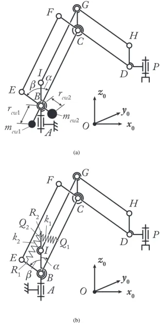
The gravity balancing of the manipulator will be achieved if and only if the potential energy becomes con-stant. For that, two usual methods are possible:
• the addition of two counterweights on linksBC and EB (Fig. 2(a)),
• the addition of two zero-free length springs on linksBC
andEB (Fig. 2(b)).
C.1 Balancing of the manipulator by adding counter-weights
Let us denote as (Fig. 2(a)):
• mcw1the mass of the counterweight on linkBC which is located at the distancercw1of the R joint at pointB, • mcw2the mass of the counterweight on linkEB which is located at the distancercw2of the R joint at pointB.
The potential energyVcwof the counterweights is given by:
Vcw= −g(mcw1rcw1cos α + mcw2rcw2cos β) (16) The total potential energyV + Vcwis thus constant (i.e. the robot is gravity-balanced) if and only if the counter-weights are designed such that:
mcw1= a/(g rcw1) (17) mcw2= b/(g rcw2) (18)
A
B
C
D
P
E
F
G
H
I
x0
z0
y0
O
β
α
m
cw2m
cw1r
cw1r
cw2 (a)A
B
C
D
P
E
F
G
H
I
x0
z0
y0
O
β
α
k
1k
2Q
1Q
2R
2R
1 (b)Fig. 2. Balancing of the robot manipulator under consideration. (a) via counterweights, (b) via zero-free length springs
C.2 Balancing of the manipulator by adding zero-free length springs
Let us denote as (Fig. 2(b)):
• k1the stiffness of the spring on linkBC acting between the pointsQ1andQ2,
• k2the stiffness of the spring on linkEB acting between the pointsR1andR2.
The potential energyVspof the zero-free length springs is given by: Vsp= k1ℓ 2 Q1Q2+ k2ℓ 2 R1R2 2 (19)
Noting the fact that: ℓ2 Q1Q2 = ℓ 2 BQ1+ ℓ 2 BQ2− 2ℓBQ1ℓBQ2cos α (20) ℓ2 R1R2 = ℓ 2 BR1+ ℓ 2 BR2− 2ℓBR1ℓBR2cos β (21)
and introducing it into (19), we get:
Vsp= −k1ℓBQ1ℓBQ2cos α−k2ℓBR1ℓBR2cos β +d (22)
whered is a constant equal to d =k1(ℓ 2 BQ1+ ℓ 2 BQ2) + k2(ℓ 2 BR1+ ℓ 2 BR2) 2 (23)
The total potential energyV + Vspis thus constant (i.e. the robot is gravity-balanced) if and only if the springs are designed such that:
k1ℓBQ1ℓBQ2 = a (24) k2ℓBR1ℓBR2 = b (25)
Now that we have considered the balancing of the robot, let us consider the balancing of the variable payload. III. Adaptive gravity-balacing system
In the following of this Section, we consider that the robot manipulator is self-balanced using one of the method proposed in the previous Section (the balancing solutions will not be drawn on the following pictures for reason of drawing clarity) and we only focus on the balancing of the variable payload.
A. Description of the adaptive gravity-balacing system
In order to ensure the balancing of the variable payload, it is necessary to achieve the following modifications to the robot architecture.
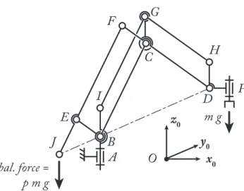
First, we slightly modify the robot architecture by adding a revolute joint on the linkEF at a new point J defined
such that the points B, D and J are aligned (Fig. 3).
With the new design, the robot becomes a pantograph link-age [37] with a magnification factorp = ℓEF/ℓEJ which links the position of pointD to the position of point J such
that:
zD− zB= p(zB− zJ) (26) Thanks to this design and the well-kown pantograph properties [38], it is possible to cancel the gravity effect of a massm applied at point P (f = m g) by applying a
vertical balancing force of magnitudefbal= p g m at point
J.
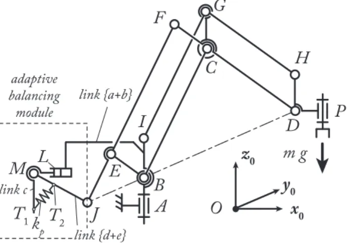
Then, in order to apply the vertical balancing force at point J, we add the balancing module to the robot (see
Fig. 4). This module is made of four joints (three prismatic (P) joints located at pointsK, L and N and one revolute (R)
A
B
C
D
P
E
F
G
H
I
x
0z
0y
0O
m g
bal. force =
p m g
J
Fig. 3. Modification of the robot architecture so that it becomes a panto-graph linkage.
A
B
C
D
P
E
F
G
H
I
x
0z
0y
0O
m g
J
L
M
T
1k
T
2 pK
N
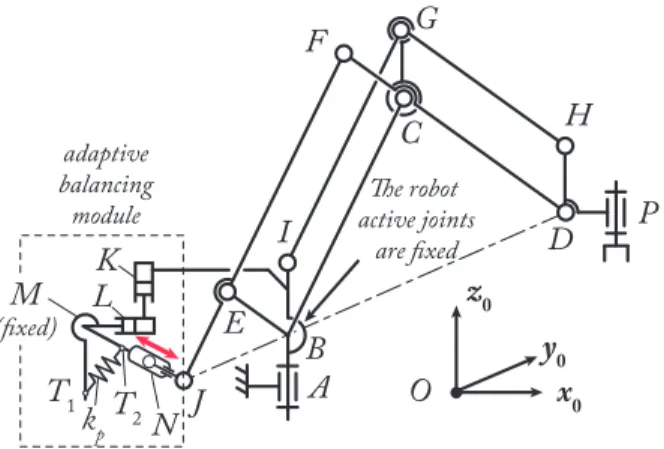
adaptive balancing module link a link b link c link e link dFig. 4. The robot with the adaptive balancing module.
joint at pointM ) and one zero-free length spring of stiffness kpattached at pointsT1andT2with the lengthsℓM T1 and ℓM T2always constant. In this module:
• the P joint at pointK is passive but it integrates a brake that is activated when the robot is manipulating a constant load and deactivated when the balancing module is adapting to a new payload,
• the P joint at point N integrates a motor plus a brake: when the robot manipulates a constant load, the brake is activated and the motor is shut down, while, when the bal-ancing module is adapting to a new payload, the motor is activated and the brake is deactivated,
• the R joint at pointM and the P joint at point L are pas-sive but they integrate brakes that are deactivated when the robot is manipulating a constant load and activated when the balancing module is adapting to a new payload.
This adaptive module is able to ensure the balancing of the variable payload for any robot configuration. Moreover, the adaption does not need to bring additional energy as
A
B
C
D
P
E
F
G
H
I
x
0z
0y
0O
m g
J
L
M
T
1k
T
2 p adaptive balancing module link {a+b} link c link {d+e}Fig. 5. The robot with the adaptive balancing module and a payload mass
m: the P joints at points K and N are fixed while the others joints of the
adaptive module are passive.
all the requested energy is already stored in the spring of stiffness kp. In the following sections, we explain how it works.
B. Balancing conditions B.1 For a payload massm
As mentioned previously, during the manipulation of a constant payload of massm, the P joints at points K and N
are fixed via brakes, while the other joints are passive, and the resulting mechanism is depicted at Fig. 5. When the
P joints at pointsK and N are fixed, the balancing
mod-ule has two planar passive DOF which makes it possible to follow the displacement of the pointJ. Moreover,
• the lengthℓM J becomes constant and will be denoted as
ℓM J = ℓm,
• the altitudezM of the pointM becomes constant. Let us show that under certain conditions, the balancing module ensure the gravity compensation of the payload. We define the angleγ as γ∠T1M T2(γ is not constant and de-pends on the robot configuration). The energy of the zero-free length spring with a stiffnesskpis equal to:
Vbal=
kpℓ2T1T2
2 (27)
or also, when considering thatℓ2
T1T2 = ℓ 2 M T1 + ℓ 2 M T2 − 2ℓM T1ℓM T2cos γ Vbal= e − kpℓM T1ℓM T2cos γ (28) where e =kp(ℓ 2 M T1+ ℓ 2 M T2) 2
For reasons of simplicity of computation, we consider that the centre of mass:
• of the link between pointsM and N is located at M ,
• of the link between pointsN and J is located at J and has a massmJ.
Such conditions can be obtained through a proper link de-sign and, eventually, the use of counterweights. Note that these conditions are not necessary, but simplifies the expla-nation of the ways the balancing module works.
The potential energy of the payload mass plus the bal-ancing module is
Vm= m g zP+ mJzJ+ mmodg zM (29) wheremmodis the total mass of the linksa, b, c and d, and
zM is the constant altitude of the pointM .
Noting the fact that zP = zD and introducing (26) into (29), we get
Vm=m g (p(zB− zJ) + zB) + mJg zJ+ mmodg zM
=h + (mJ− p m) g zJ
(30) withh = m g (p + 1)zB+ mmodg zM = constant.
Finally, aszJ = zM − ℓM Jcos γ = zM − ℓmcos γ, we get
Vm=h + (mJ− p m) g (zM− ℓmcos γ)
=l + (p m − mJ) g ℓmcos γ
(31)
withl = h + (mJ− p m) g zM = constant.
The balancing module can cancel the gravity effects of the payload mass m if the total potential energy Vtot =
Vm+ Vbalis equal to a constant, which can be obtained if and only if (for fixed lengthsℓM T1,ℓM T2and stiffnesskp):
ℓm=
kpℓM T1ℓM T2 (p m − mJ) g
(32) resulting inVtot= e + l = constant.
Thus, by properly fixing the lengthℓm = ℓM J, we can balance the payload mass. Note that in general, (p m − mJ) > 0, which means that ℓm> 0.
B.2 Adaption to a new payload massm′
If now we want to balance a payload massm′, by using the equation (32), we see that the lengthℓM J should adapt to a new constant lengthℓ′
mdefined as:
ℓ′ m=
kpℓM T1ℓM T2
(p m′− mJ) g (33) This adaption can be energy-free by using the following procedure. First, the robot must be stopped at the position the payload should be changed (fig. 6(a)). Thus, the alti-tudezP becomes constant. Then, the R joint at point M is also fixed while the brake of jointK is deactivated such
that the global system is equivalent to the one depicted in Fig. 6. Note that, when the R joint at pointM is fixed, this
A
B
C
D
P
E
F
G
H
I
x
0z
0y
0O
J
L
T
1T
2k
pK
N
adaptive balancing module The robot active joints are fixedM
(fixed)(a)Beginning of the adaption: the robot is stopped. The P joint at point K becomes passive while the R joint at point M is fixed (thus ensuring the spring potential energy to be stored). The P joint at point N is actuated to adapt the length ℓM J.
A
B
C
D
P
E
F
G
H
I
x
0z
0y
0O
J
L
M
T
1T
2k
pK
N
adaptive balancing module(b)End of the adaption: the system has attained the new length ℓM J =ℓ′m
A
B
C
D
P
E
F
G
H
I
x
0z
0y
0O
J
L
M
T
1k
p adaptive balancing modulem’ g
The robot active joints are now free(c)The robot with the adaptive balancing module when manipulating a mass m′: the P joints at points K and N are fixed while the others joints of the adaptive module are passive.
Fig. 6. Adaption of the balancing system
Counterweights of total mass mmod
Element fixed to the link b Pulley Element fixed on the link a
Fig. 7. Balancing device for cancelling the gravity effects due to the mass of the adaptive module: the counterweights are moving in the opposite sense of the link b and are thus balancing the moving mass of the gravity-compensation module.
also fix the lengthℓP1P2 of the spring. As a result, during
the adaption phase, the spring energy is totally stored (no energy dissipation).
The P joints at points K and L are passive while the P joint at point N is actuated. A simple mobility
analy-sis shows that the balancing module has thus 1 DOF which can be controlled by the actuator in the P joint located at pointN . This active P joint will be used to adapt the length ℓM J to become equal toℓ′m(Fig. 6(b)).
The robot being fixed, when the active P joint is mov-ing, the change of potential energy is only due to the dis-placement of the links of the balancing module during its adaption. This variation∆V of energy is equal to:
∆V = mmodg ∆zM (34) where∆zM is the variation of altitude of the pointM due to the module adaption. This variation of potential energy can be cancelled through a proper balancing system such as the one presented in [39] which is depicted at Fig. 7.
Thus, as the variation of potential energy is null during the adaption phase, the robot does not need (theoretically) any additional energy to adapt to the new payloadm′, that will be compensated thanks to the optimal adjustment of the lengthℓ′
mdefined in (33). Once the adaption is done, the robot is gravity-balanced for the new payloadm′, i.e. the robot actuators do not need to compensate the gravity effects of the massm′(Fig. 6(c)).
C. Discussion
In the previous Section, it has been mentioned that, dur-ing the adaption phase, the robot must be stopped, which will lead to a increase of the operation cycle time. How-ever, in the other techniques [28, 31–35] able to balance a variable load, the robot should also be stopped during the adaption. Thus, stopping the robot is not a drawback due to our balancing technique, but to all adaptive balancing tech-niques. In order to overcome this drawback, the adaption can be down when the robot is moving. However, this does
not ensure anymore the system to be energy-free during the adaption phase.
Please note also that we claim that the adaption is energy-free. However, we do not take into account the fact that the actuator in the P joint located at pointN needs energy to
move against the friction in the joint. However, our expe-rience in the field has shown that the friction effects are usually very small with respect to the gravity effects which have been compensated.
Finally, the conditions of balancing for the payload de-scribed in (32) show that, ifm = 0, the length ℓM should be negative, which is unconvenient from a design point of view. In order to overcome this difficulty, two ways are proposed:
1. we can put a loadmc > mJ on the robot end-effector that will never be removed to ensure that the lengthℓM will be always positive.
2. it is possible to show in Section II-C that a partial gravity-balancing of the robot architecture can be achieved with counterweights and/or springs so that the potential gravitational energy of the robot becomes a linear func-tion ofzP only, i.e. the robot potential energy has the form
V = mPzP+ constant, with mP > 0. In such a case, the balancing condition (32) can be rewritten as:
ℓm=
kpℓM T1ℓM T2 (p (m + mP) − mJ) g
(35) As a result, an optimal design of the robot can ensure that the term(p m + mP − mJ) is always positive.
IV. Numerical validations
In this Section, we present numerical validations made with ADAMS showing that the balancing system is able to compensate a variable payload. We will consider in the following of the Section that the robot is self-balanced by using one of the techniques of Section II. This assumption is made because the paper does not focus on the balancing of the robot itself (which is achieved trough the use of very common techniques which have already been validated in the past) but on the gravity-compensation obtained by the use of the adaptive module.
The simulated robot has the following characteristics: • the origin of the base frame is at pointB, and the point P
(position of the end-effector) is superposed with the point
D,
• the robot length are:ℓBC = 1.3 m, ℓCD = 1.3 m, ℓGH=
1.3 m, ℓBE = 0.3 m, ℓCF = 0.3 m, ℓBI = 0.3 m, ℓCG=
0.3 m and ℓDH= 0.3 m.
The gravity-compensation module is designed such that: • the lengthℓEJis equal to 0.3 m; as a result, the resulting pantograph mechanism of Fig 3 has a magnification factor
p = 1.3/0.3 ≈ 4.33,
• the total mass of linksb, c and d is equal to mmod =
10 kg, but is compensated through the addition of the
sys-0 2 4 6 8 10 0.7 0.8 0.9 1 1.1 1.2 1.3 1.4 Time (sec.) Position (m) xP zP
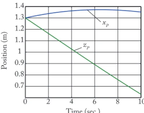
Fig. 8. Trajectory during the manipulation of the payload m = 100 kg, defined for yP= 0m.
tem designed in Fig. 7 with counterweights of total mass equal to 10 kg,
• the total centre of mass of linksb, c and d is located at pointM ,
• the mass of the linke is mJ= 5 kg and its centre of mass is located in pointJ,
• the spring has a stiffnesskp= 20000 N/m.
First, the robot has to manipulate a payload of massm = 100 kg. As a result, the length ℓM J of the module should be equal toℓM = 0.467 m to balance the gravity effects of the payloadm. The payload is manipulated by the robot
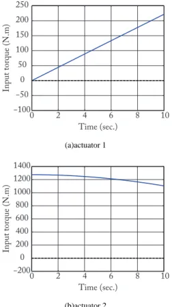
on the trajectory defined in Fig. 8. The results in terms of robot input torques (Fig. 9) required for manipulating this payload without the gravity-compensation module (full line) and with the gravity-compensation module with the lengthℓM J equal toℓM = 0.467 m (dotted line) show that, with the use of the adaptive module, no input torques are required to move the payload.
Then, at the end of the trajectory defined in Fig. 8 (at the pointxP = 1.35 m, yP = 0 m and zP = 0.63 m), we change the load and the robot must be able to carry out a mass ofm′ = 300 kg. As a result, the length ℓ
M J of the module should be equal toℓ′
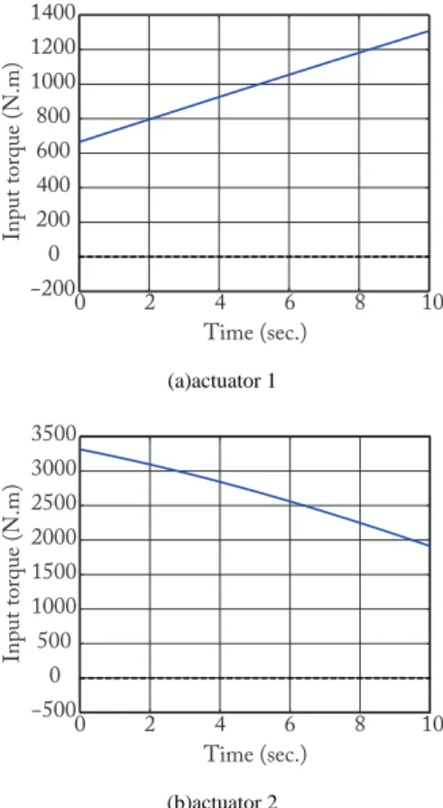
M = 0.155 m to balance the gravity effects of the payloadm′. We do not show here the variation of potential energy during the process of adaption to the new length because it is equal to zero all the time, i.e. the compensation module does not bring energy to adapt to the new length. The new payload is manipulated by the robot on the trajectory defined in Fig. 10. The results in terms of robot input torques (Fig. 11) required for manipu-lating this payload without the gravity-compensation mod-ule (full line) and with the gravity-compensation modmod-ule with the lengthℓM J equal toℓM = 0.467 m (dotted line) show that, with the use of the adaptive module, no input torques are required to move the payload.
V. Conclusion
In this paper, a new gravity-compensation module for
−100 −50 0 50 100 150 200 250 0 2 4 6 8 10 Time (sec.) Input torque (N.m) (a)actuator 1 −200 0 200 400 600 800 1000 1200 1400 0 2 4 6 8 10 Time (sec.) Input torque (N.m) (b)actuator 2
Fig. 9. Input torques for manipulating the payload m = 100 kg: without (full line) and with (dotted line) the gravity-compensation module.
proposed. The new balancing scheme allows for the com-pensation of the gravity effects of the manipulated payload which may vary. Contrary to most of gravity balancing techniques able to compensate the gravity effects of vari-able loads, this compensation module is energy efficient, i.e. the adaption to the new manipulated payload does not require to bring energy inside the system.
Simulations of the mechanism with ADAMS have been performed and have shown the efficiency of the proposed approach.
Future works will concern the optimal design of a proto-type in order to experimentally validate this balancing tech-nique which can find wide applications to the solution of practical problems.
References
[1] G. Dunlop and T. Jones. Gravity counter balancing of parallel robot for antenna aiming. In Proceedings of the 6th ASRAM, pages 153– 158, 1996.
[2] H. Kazerooni and S. Kim. A new architecture for direct drive robots. In Proceedings of the IEEE International Conference on Robotics
and Automation (ICRA 1988), pages 442–445, 1988.
[3] H. Kazerooni. Statically balanced direct drive manipulator.
Robot-ica, 7(2):143–149, 1989.
[4] C.M. Gosselin and J. Wang. On the design of gravity-compensated six-degree-of-freedom parallel mechanisms. In Proceedings of the
IEEE International Conference on Robotics and Automation (ICRA 1998), pages 2287–2294, Leuven, Belgium, 1998.
0 0.2 0.4 0.6 0.8 1 1.2 1.4 0 2 4 6 8 10 Time (sec.) Position (m) xP zP
Fig. 10. Trajectory during the manipulation of the payload m′= 300kg,
defined for yP= 0m.
[5] J. Wang and C.M. Gosselin. Static balancing of spatial three-degree-of-freedom parallel mechanisms. Mechanism and Machine Theory, 34:437–452, 1999.
[6] W.S. Newman and N. Hogan. the optimal control of balanced ma-nipulators. In Proceedings of the ASME winter annual meeting, CA, USA, 1986.
[7] C.M. Gosselin. Smart Devices and Machines for Advanced
Man-ufacturing, chapter Gravity compensation, static balancing and
dy-namic balancing of parallel mechanisms, pages 27–48. Springer, 2008.
[8] J. Wang and C.M. Gosselin. Static balancing of spatial four-degree-of-freedom parallel mechanisms. Mechanism and Machine Theory, 35(4):563–592, 2000.
[9] T. Lalibert´e, C.M. Gosselin, and M. Jean. Static balancing of 3-DOF planar parallel mechanisms. IEEE/ASME Transactions on
Mecha-tronics, 4(4):363–377, 1999.
[10] A. Gopalswamy, P. Gupta, and M. Vidyasagar. A new parallel-ogram linkage configuration for gravity compensation using tor-sional springs. In Proceedings of the IEEE International Conference
on Robotics and Automation (ICRA 1992), pages 664–669, Nice,
France, may 1992.
[11] E. Shin and D.A. Streit. Spring equilibrator theory for static balanc-ing of planar pantograph linkages. Mechanism and Machine Theory, 26(7):645–657, 1991.
[12] D.A. Streit and E. Shin. Equilibrators for planar linkages. ASME
Journal of Mechanical Design, 115:604–611, 1993.
[13] T. Rahman, R. Ramanathan, R. Seliktar, and W. Harwin. A sim-ple technique to passively gravity-balance articulated mechanisms.
ASME Journal of Mechanical Design, 117(4):655–658, 1995.
[14] J.L. Pons, R. Ceres, and A.R. Jim´enez. Quasi-exact linear spring counter gravity system for robotic manipulators. Mechanism and
Machine Theory, 33:59–70, 1998.
[15] C.M. Gosselin. Computational Methods in Mechanical Systems: Mechanism Analysis, Synthesis, and Optimization, chapter On the
design of efficient parallel mechanisms, pages 68–96. NATO ASI. Springer, Berlin, 1998.
[16] J.L. Herder. Design of spring force compensation systems.
Mecha-nism and Machine Theory, 33:151–161, 1998.
[17] I. Ebert-Uphoff, C.M. Gosselin, and T. Lalibert´e. Static balancing of spatial parallel mechanisms revisited. ASME Journal of Mechanical
Design, 122:43–51, 2000.
[18] G.J.M. Tuijthof and J.L. Herder. Design, actuation and control of an antropomorphic robot arm. Mechanism and Machine Theory, 35:945–962, 2000.
[19] Y. Ono and T. Morita. An underactuated manipulation method using a mechanical gravity canceller. Journal of Robotics and
Mechatron-ics, 106(6):563–569, 2004.
[20] P.Y. Lin, W.B. Shieh, and D.Z. Chen. Design of perfectly statically balanced one-DOF planar linkage with revolute joints only. ASME
Journal of Mechanical Design, 131, 2009.
[21] P.Y. Lin, W.B. Shieh, and D.Z. Chen. A stiffness matrix approach for the design of statically balanced planar articulated manipulators.
−200 0 200 400 600 800 1000 1200 1400 0 2 4 6 8 10 Time (sec.) Input torque (N.m) (a)actuator 1 −500 0 500 1000 1500 2000 2500 3000 3500 0 2 4 6 8 10 Time (sec.) Input torque (N.m) (b)actuator 2
Fig. 11. Input torques for manipulating the payload m′= 300kg:
with-out (full line) and with (dotted line) the gravity-compensation module.
[22] Q. Lu, C. Ortega, and O. Ma. Passive gravity compensation mecha-nisms: Technologies and applications. Recent Patents on
Engineer-ing, 5(1):32–44, 2011.
[23] P.Y. Lin, W.B. Shieh, and D.Z. Chen. Design of statically balanced planar articulated manipulator with spring suspension. IEEE
Trans-actions on Robotics, 28(1):12–21, 2012.
[24] S.D. Deepak and G.K. Ananthasuresh. Static balancing of a four-bar linkage and its cognates. Mechanism and Machine Theory, 48:62– 80, 2012.
[25] S.D. Deepak and G.K. Ananthasuresh. Perfect static balancing of linkages by addition of springs but not auxiliary bodies. ASME
Jour-nal of Mechanisms and Robotics, 4, 2012.
[26] A. Bayer and G. Merk. Industrial robot with a weight balancing system, aug 2011.
[27] P.N. Belyanin. Balanced manipulators. Mashinostroyenie, Moscow, 1988.
[28] A. Fahim and M. Fernandez. Performance enhancement of robot arms through active counterbalancing. International Journal of
Ad-vanced Manufacturing Technology, 3(4):63–72, 1988.
[29] R. Yamamoto, A. Hirakawa, and O. Horikawa. Load balancer with automatic lifting force compensation. In Proceedings of the ABCM
Symposium in Mechatronics, volume 4, pages 580–589, 2010.
[30] F. Wildenberg. Compensating system for a hexapod. Patent us 6474915, nov 2002.
[31] M. Carricato and C.M. Gosselin. A statically balanced Gough/Stewart-type platform: Conception, design, and simulation.
ASME Journal of Mechanisms and Robotics, 1, 2009.
[32] N. Takesue, T. Ikematsu, H. Murayama, and H. Fujimoto. Design and prototype of variable gravity compensation mechanism. Journal
of Robotics and Mechatronics, 23(2):249–257, 2011.
[33] N. Lauzier, C.M. Gosselin, T. Lalibert´e, and P. Tremblay. Adaptive gravity compensation of decoupled parallel and serial manipulators using a passive hydraulic transmission. Journal of Mechanical
En-gineering Science, 223(12):2871–2879, 2009.
[34] M.A. Lacasse, G. Lachance, J. Boisclair, J. Ouellet, and C.M. Gos-selin. On the design of a statically balanced serial robot using remote counterweights. In Proceedings of the IEEE International
Confer-ence on Robotics and Automation (ICRA 2013), pages 4174–4179,
Karlsruhe, Germany, may 2013.
[35] T. Lalibert´e, C.M. Gosselin, and D. Gao. Closed-loop actuation routings for cartesian scara-type manipulators. In Proceedings of
the 2010 International Design Engineering Technical Conferences & Computers and Information in Engineering Conference (IDETC/CIE 2010), aug 2010.
[36] S. Briot and V. Arakelian. Dispositif d´equilibrage de charge pour bras articul´e, appareil et proc´ed´e de manipulation de charge associ´e. FR 14 62980, dec 2014. patent pending.
[37] V. Arakelian. ´equilibrage des manipulateurs manuels. Mechanism
and Machine Theory, 33(4):437–442, 1998.
[38] S. Briot, V. Arakelian, and S. Gu´egan. Paminsa: a new family of decoupled parallel manipulators. Mechanism and Machine Theory, 44(2):425–444, 2009.
[39] V. Arakelian and S. Briot. Dynamic balancing of the scara robot. In
Proceedings of 17th CISM-IFToMM Symposium on Robot Design, Dynamics, and Control (RoManSy 2008), Tokyo, Japan, 2008.