HAL Id: tel-00429417
https://tel.archives-ouvertes.fr/tel-00429417
Submitted on 2 Nov 2009
HAL is a multi-disciplinary open access
archive for the deposit and dissemination of sci-entific research documents, whether they are pub-lished or not. The documents may come from teaching and research institutions in France or abroad, or from public or private research centers.
L’archive ouverte pluridisciplinaire HAL, est destinée au dépôt et à la diffusion de documents scientifiques de niveau recherche, publiés ou non, émanant des établissements d’enseignement et de recherche français ou étrangers, des laboratoires publics ou privés.
embarqués parallèles : modélisation des systèmes et
amélioration des heuristiques d’ordonnancement de
tâches
Pengcheng Mu
To cite this version:
Pengcheng Mu. Méthodologie de prototypage rapide pour systèmes embarqués parallèles : modéli-sation des systèmes et amélioration des heuristiques d’ordonnancement de tâches. Modélimodéli-sation et simulation. INSA de Rennes, 2009. Français. �tel-00429417�
Ecole Doctorale MATISSE
THESE
présentée devantL’INSTITUT NATIONAL DES SCIENCES APPLIQUÉES DE
RENNES
pour obtenir le grade de
DOCTEUR
spécialité : Traitement du Signal et de l’Image
Rapid Prototyping Methodology for Parallel
Embedded Systems
Advanced System Model and Improved Task Scheduling Heuristics
parMU Pengcheng
Soutenance prévue le 07/07/2009 devant la commission d’Examen Composition du jury:
Rapporteurs
BOURENNANE El-Bay Professeur des Universités à l’Université de Bourgogne HOUZET Dominique Professeur des Universités à l’INPG de Grenoble Examinateurs
GRANDPIERRE Thierry Professeur Associé à l’ESIEE, Noisy-le-Grand VERDIER François Maître de Conférences (HDR) à l’ETIS COUSIN Jean-Gabriel Maître de Conférences à l’INSA de Rennes NEZAN Jean-François Maître de Conférences à l’INSA de Rennes Directeur de thèse
RONSIN Joseph Professeur des Universités à l’INSA de Rennes
Institut d’Electronique et de Télécommunications de Rennes Institut National des Sciences Appliquées de Rennes Université Européenne de Bretagne
Contents iii
Introduction 1
1 Rapid Prototyping and Hardware/Software Co-design 5
1.1 Introduction . . . 5
1.2 Design FPGA based MPSoC with AAA Rapid Prototyping Methodology 6 1.2.1 AAA Rapid Prototyping Methodology and SynDEx . . . 6
1.2.2 Rapid Prototyping for Multi-MicroBlaze Systems on FPGA . 8 1.2.3 SynDEx-Ic Tool . . . 12
1.3 Tools for HDL Code Generation . . . 13
1.3.1 GAUT: A High-Level Synthesis Tool . . . 14
1.3.2 Open Dataflow Framework . . . 16
1.3.3 Comparison between GAUT and OpenDF . . . 21
1.4 An Eclipse-Based Open Source Rapid Prototyping Framework . . . . 22
1.4.1 Graphiti: A Generic Graph Editor for Editing Architectures, Algorithms and Workflows . . . 23
1.4.2 SDF4J: A Java Library for Algorithm Dataflow Graph Trans-formation . . . 25
1.4.3 PREESM: A Complete Framework for Hardware/Software
Co-design . . . 27
1.5 Conclusion . . . 28
2 Graph Models for Parallel Embedded Systems 29 2.1 Introduction . . . 29 2.2 Algorithm Model . . . 30 2.2.1 Dataflow Model . . . 30 2.2.2 DAG Model . . . 34 2.2.3 DAG Properties . . . 36 2.3 Architecture Model . . . 43 2.3.1 Parallel Architectures . . . 43
2.3.2 Advanced Architecture Model . . . 45
2.3.3 Architecture Specification with IP-XACT Standard . . . 51
2.4 Conclusion . . . 53
3 Task Scheduling in Parallel Embedded Systems 55 3.1 Introduction . . . 55
3.2 General Task Scheduling . . . 56
3.2.1 Without/With Communication Costs . . . 56
3.2.2 Scheduling Methodologies . . . 58
3.2.3 Advanced Techniques . . . 60
3.3 Task Scheduling with Advanced Architecture Model . . . 63
3.3.1 Routing with Architecture Model . . . 63
3.3.2 Scheduling with Advanced Architecture Model . . . 65
3.3.3 Causality Conditions . . . 68
3.3.4 Scheduling Conditions . . . 69
3.4 Task Scheduling with Topology Graph Model . . . 71
3.4.1 Topology Graph Model . . . 71
3.4.2 Scheduling with Communication Contention . . . 73
3.5 Conclusion . . . 75
4 List Scheduling with Communication Contention 77 4.1 Introduction . . . 77
4.2 Node Levels with Communication Contention . . . 78
4.3.1 Static List Scheduling Heuristic . . . 82
4.3.2 Dynamic List Scheduling Heuristic . . . 85
4.4 Experimental Results . . . 86
4.4.1 Comparison with an Example . . . 87
4.4.2 Comparison with Randomly Generated DAGs . . . 89
4.5 Analysis of Time Complexity . . . 95
4.6 Conclusion . . . 97
5 Advanced List Scheduling Methods 99 5.1 Introduction . . . 99
5.2 Processor Selection with Critical Child . . . 100
5.3 Node and Edge Scheduling with Communication Delay . . . 102
5.3.1 Node Scheduling . . . 102
5.3.2 Edge Scheduling . . . 103
5.4 Advanced List Scheduling Heuristics . . . 104
5.5 Experimental Results . . . 105
5.5.1 Comparison with an Example . . . 106
5.5.2 Comparison with Randomly Generated DAGs . . . 108
5.6 Time Complexity of Advanced List Scheduling Heuristics . . . 114
5.7 Conclusion . . . 118
Conclusions and Prospects 119 A IP-XACT Code of Advanced Architecture Model 123 A.1 TI’s C6474 DSP . . . 123
A.2 Xilinx’s FPGA-based MPSoC . . . 128
List of Figures 135 List of Tables 139 List of Algorithms 141 Personal Publications 143 Bibliography 145 Index 157
Context
Embedded systems are pervasive around our everyday life. An embedded system is an electronic system dedicated to specific applications. These systems especially exist as consumer electronics: PDAs, mp4 players, mobile phones, videogame consoles, digital cameras, DVD players, GPS receivers, etc. Most of these systems consist in digital signal processing and/or image processing applications that require a lot of processing power.
Specific hardware circuits overcome speed constraints but are not compatible with a short time-to-market. They also need early and evaluative demonstration proto-types. An alternative can be provided by programmable software components like Digital Signal Processor (DSP) and Reduced Instruction Set Computer (RISC) or programmable hardware components like Field-Programmable Gate Array (FPGA). However, only one embedded processor is usually not sufficient for modern compli-cated applications.
As the complexity of the digital signal processing applications increases, multiple processing units are necessary in an embedded system to satisfy the requirement of great computation ability. An embedded system with several cores (e.g. multi-core DSP from TI(1)) and/or several hardware accelerators (e.g. IPs for Intellectual
Properties) becomes a parallel embedded system. Hard real-time constraint must be satisfied by the multicomponent architecture, and the design can provide considerable flexibility since DSP, RISC and FPGA are programmable. However, for an embedded system with several processing cores, the flexibility is limited by the system’s fixed topological structure and the fixed number of the programmable components.
More recent FPGAs offer very dense integration. With the help of multi-million gate configurable logic and various heterogeneous FPGA hardware components (mul-tipliers, memory blocks, etc.), soft and hard processors could now be integrated on FPGA. Examples of such soft RISC processors include Nios from Altera(2) and
Mi-croBlaze from Xilinx(3). In addition, Xilinx has also integrated the PowerPC 405
hard core on its FPGA. With multiple processors integrated on FPGA, we can build up FPGA based Multiprocessor System-on-Chip (MPSoC). As an example of the re-search for multiprocessor system, ATLAS is developed in the RAMP project(4) and is a prototype including 9 PowerPC 405 cores where 8 cores run multithreaded code for applications and the 9th core handles the operation system and I/O devices. Another example is the SocLib project(5) that addresses MPSoC.
MPSoC offers flexibility and efficiency, not only as regards its software but also as regards its hardware. Designers can directly elaborate several scenarios for ar-chitecture and algorithmic design exploring to reach real-time constraints, and the time-to-market is shorter in comparison with specific hardware circuits. However, such “manual explorations” are still complex, needing strong expertise and resulting in important time development. Therefore, “automatic solutions” with rapid proto-typing methodologies are necessary for developing MPSoC.
Objective
Applications like digital signal processing usually consist of a set of tasks that are computations and communications between computations. Task scheduling is nec-essary when implementing such an application in a parallel computer system. Task scheduling consists in assigning and ordering computations and communications re-spectively to processors and communication links of the target system in order to finish all the tasks as soon as possible. The general task scheduling problem has been
(2). http://www.altera.com (3). http://www.xilinx.com
(4). http://ramp.eecs.berkeley.edu/ (5). https://www.soclib.fr/
proven to be NP-hard, therefore, many works try to find heuristics for approaching the optimal solution. Early scheduling heuristics do not take communication into account. As the communication increases in modern applications, many heuristics now consider communication for task scheduling, and most of them use fully con-nected topology network in which all communications can be performed concurrently. Arbitrary processor networks are then used to accurately describe parallel computer systems, where communication links are not contention-free, and task scheduling takes communication contention into account.
This thesis mainly concerns the task scheduling problem in rapid prototyping for parallel embedded systems (e.g. MPSoC). We aim at task scheduling models for parallel embedded systems by accurately considering communications between computations. We also propose list scheduling heuristics with advanced techniques to improve the scheduling performance. Our scheduling methods are integrated in PREESM (Parallel & Real-time Embedded Executives Scheduling Method)(6) that is
an Eclipse-based open source rapid prototyping framework. Scheduling is an impor-tant step in PREESM. The schedule result of an application on a parallel embedded system with our advanced heuristics will be further used to generate the code and finally to efficiently implement the application on the parallel embedded system.
Organization
After being briefly introduced, the rest of this work is organized in 5 chapters as follows.
Chapter 1 presents the rapid prototyping and hardware/software co-design prob-lems. We firstly present the AAA (Adequation Algorithm Architecture) rapid proto-typing methodology used for FPGA based multiprocessor system. Two different tools for generating Hardware Description Language (HDL) code from high-level languages are also presented. We introduce our rapid prototyping framework for hardware/soft-ware co-design at the end of this chapter.
Chapter 2 presents necessary graph models for rapid prototyping and hardware/-software co-design. We present several dataflow graphs to describe an application algorithm for parallel programming. As for task scheduling, the Directed Acyclic Graph (DAG) model is used to describe the application algorithm. Properties of the DAG model are also presented in details. The target system usually has the
distributed memory architecture for parallel embedded systems. We propose a graph-based advanced architecture model to accurately describe parallel embedded systems. The advanced architecture model can be specified in a graph editor by respecting the IP-XACT standard.
Chapter 3 presents the task scheduling problem in parallel embedded systems. After a survey of the general task scheduling, we present the task scheduling with our advanced architecture model in detail. Since it is difficult to implement the task scheduling with the advanced architecture model at the very start, the advanced archi-tecture model is slightly simplified to be the topology graph model. The scheduling problem with this simplified architecture model is the task scheduling with com-munication contention, and we will propose advanced techniques of this simplified scheduling for parallel embedded systems.
Chapter 4 presents list scheduling heuristics for the topology graph model (sim-plified architecture model in Chapter3). We propose three new groups of node levels with communication contention that are used for generating static and dynamic node lists. With the addition of the other two existing groups of node levels, these five groups are all used in a list scheduling heuristic, which gives a combined heuristic. Experimental results are given at the end of this chapter to show the improvement of the scheduling performance. The time complexity of the list scheduling heuristic is also analyzed and tested to show its rapidity.
Chapter 5gives two advanced techniques respectively named the critical child and the communication delay to extend the list scheduling heuristics of Chapter 4. These two techniques are combined with the five groups of node levels to further improve the scheduling performance. Though the time complexity increases by a factor of the number of processors, our experimental results show that the scheduling performance are greatly improved and the time complexity is acceptable.
1
Rapid Prototyping and
Hardware/Software Co-design
1.1
Introduction
The multicomponent architecture of MPSoC [Mar06] raises problems in terms of application distribution: manual data transfers and synchronizations quickly become very complex and result in loss of time and potential deadlocks.
One suitable design process solution consists in using rapid prototyping method-ology. The aim is then to go from a high-level description of the application to its real-time implementation on target architecture as automatically as possible. This automation saves development time and prevents conflicts and deadlocks. It ensures processing safety and reduces validation tests.
Hardware/software co-design [MG97] has been proposed as the design method for embedded systems and is used for designing System-on-Chip (SoC) [SBB06,OH06]. It needs to generate code for hardware coprocessors in Hardware Description Language (HDL) that is usually more complicated than software code. A tendency is to generate HDL code from high-level languages. This topic is interesting and important for hardware/software co-design.
This chapter presents rapid prototyping and hardware/software co-design. The rest of the chapter is organized as follows: Section 1.2 presents the AAA rapid pro-totyping for FPGA based MPSoC, and we use this rapid propro-totyping methodology
for designing multi-MicroBlaze systems on FPGA with the SynDEx tool. Section 1.3
presents two tools to generate HDL code from high-level languages for hardware/soft-ware co-design. When rapid prototyping is used with hardhardware/soft-ware/softhardware/soft-ware co-design, we will need a new framework. Our new rapid prototyping framework is introduced in Section 1.4. The conclusion is given in Section 1.5.
1.2
Design FPGA based MPSoC with AAA Rapid
Prototyping Methodology
The AAA (Adequation Algorithm Architecture) rapid prototyping methodology is suitable for designing image processing systems with heterogeneous multicomponent architectures. Based on this methodology, the SynDEx(1) tool has been used in
some multi-DSP systems for image processing applications [RUN+05b]. This section
presents the use of this rapid prototyping methodology in multi-MicroBlaze systems on FPGA. An extension of SynDEx is also introduced.
1.2.1
AAA Rapid Prototyping Methodology and SynDEx
SynDEx is a free academic system level Computer Aided Design tool developed by INRIA Rocquencourt. It supports the AAA methodology [GLS99] for distributed real-time processing. The aim of SynDEx is to directly achieve optimized implementation from descriptions of an algorithm and an architecture.
AAA in SynDEx
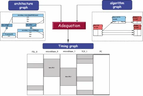
Figure 1.1 gives the SynDEx design flow. An algorithm graph is described as a Dataflow Graph (DFG), and specifies the potential parallelism of the application. An architecture graph describes the multicomponent target, i.e. a set of interconnected processors and specific integrated circuits, and specifies the available parallelism. In the application example given in Figure1.1, the algorithm graph includes one input, two outputs and a function that is divided into two identical parts to be executed simultaneously. The architecture graph of the target system is composed of one PC, two MicroBlazes and two communication media. Since these two MicroBlazes and the medium between them are all integrated on an FPGA, the architecture graph gives
a medium-coarse grain description in comparison with the one considering an FPGA as a black-box [RUN+05b].
Figure 1.1: SynDEx design flow
“Adequation” (Figure 1.1) means efficient mapping, and consists in manually or automatically exploring the space of implementation solutions with optimization heuristics [GLS99]. These heuristics aim to minimize the total execution time of the algorithm running on the multicomponent architecture. The heuristic is a greedy list scheduling based approach with manual interaction when timing constraints are not met.
Implementation consists of both performing a distribution (allocating parts of the algorithm to components) and scheduling the algorithm on the architecture (i.e. giving a total order for the operations distributed onto a component).
Formal verifications during “adequation” avoid deadlocks in the communication scheme thanks to semaphores inserted automatically during real-time code generation. Moreover, since the Synchronized Distributed Executives are automatically generated and safe, part of the tests and low-level manual coding are eliminated, decreasing the development lifecycle.
SynDEx provides a timing graph (Figure 1.1), which includes simulation results of the distributed application and thus enables SynDEx to be used as a virtual proto-typing tool. SynDEx then automatically generates the generic executives, which are independent of the hardware target, and places them in several source files, one for
each hardware target.
Automatic Executive Generation
The generic executives automatically generated by SynDEx are static and com-posed of a list of macro-calls. The M4(2)macroprocessor transforms this list of
macro-calls into compilable codes for a specific target. The codes are usually C or assemble codes for processors and VHDL for the specific functions implemented on the FPGA. The M4 macroprocessor replaces macro-calls by their definitions as given in the cor-responding executive kernel. The definitions are dependent on a target and/or a com-munication medium. In this way, SynDEx can be seen as an off-line static operating system that is suitable for setting data-driven scheduling, such as image processing applications. For examples, SynDEx kernels have been developed for several proces-sors such as General Purpose Procesproces-sors (usually on PC), TMS320C6x (C62x, C64x) DSP and Virtex FPGA families [RUN+05b]. The generated codes could then be
com-piled by specific Computer-aided design (CAD) tools such as CCS for DSP, Quartus or ISE for FPGA and Visual Studio for PC.
1.2.2
Rapid Prototyping for Multi-MicroBlaze Systems on
FPGA
The AAA rapid prototyping methodology has been used in a number of multi-DSP systems for image processing applications, and it could also be used in FPGA-based MPSoC to integrate multiple components on one or more FPGAs. As an embedded soft core, MicroBlaze is a RISC processor and optimized for implementation on Xilinx FPGA. It is highly configurable, allowing users to select a specific set of features required by their design. Integrating multiple MicroBlazes on one or more FPGAs can build up a multi-MicroBlaze MPSoC. This multi-MicroBlaze system is flexible in terms of both software and hardware, so it can be used in complicated and computation-rich applications such as image processing. This section details the use of rapid prototyping for multi-MicroBlaze systems on FPGA with SynDEx.
Design Flow
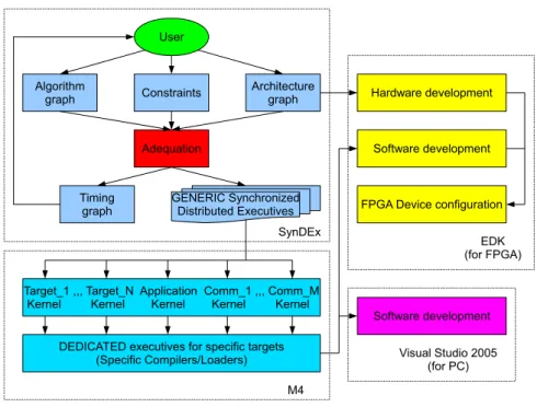
Figure1.2 shows the design flow for multi-MicroBlaze systems. A number of tools such as SynDEx, M4, Embedded Development Kit (EDK) and Visual Studio are used
for different design stages.
User
Algorithm
graph Constraints Architecturegraph
Adequation
Timing
graph GENERIC SynchronizedDistributed Executives
Hardware development
Software development
FPGA Device configuration
Software development Target_1 ,,, Target_N Application Comm_1 ,,, Comm_M
Kernel Kernel Kernel Kernel Kernel
DEDICATED executives for specific targets (Specific Compilers/Loaders) SynDEx M4 EDK (for FPGA) Visual Studio 2005 (for PC)
Figure 1.2: Rapid prototyping design flow with SynDEx
In this design flow, users firstly have to model in SynDEx Integrated Development Environment (IDE) the processors and communication media which are used in their design. Two different models are possible for the communication media between processors: Single Access Memory (SAM) and Random Access Memory (RAM, shared memory) [RUN+05b]. These modules are saved in a library and could be used for
other designs without any modifications. With these modules, users then could build up the architecture and the algorithm graphs, and the “adequation” would be done by SynDEx while the Synchronized Distributed Executives are automatically generated in the form of m4 files. The m4 files then are translated into compilable executives for specific targets such as MicroBlaze, PC and specific functions on FPGA with the help of kernels which are explained in this section.
As the codes are generated, the next step is to build up the system. For the Xilinx FPGA, EDK is used for both hardware and software developments. The hardware is equivalent to the description of FPGA in the architecture graph of SynDEx ex-cept that it is described in the finest grain with EDK and can be used to generate the bitstream that configures the FPGA. For software programming, EDK uses the generated executives for MicroBlazes and respective drivers to build up Executable Linked Format (ELF) files for the multi-MicroBlaze system. When PC is used,
Vi-sual Studio is necessary for software development using the generated executives and several drivers for PC.
SynDEx Executive Kernels
As described in Section 1.2.1, the SynDEx generic executives have to be trans-lated into a compilable language. The translation of SynDEx macros into the target language is contained in library files (also called kernels). Figure 1.3 shows the orga-nization of different kernels for the multi-MicroBlaze system. There are two types of processors (PC and MicroBlaze) and two types of communication media (Fast Sim-plex Link (FSL) and TCP/IP) in the multi-MicroBlaze system. FSL is used for the communication between MicroBlazes, and TCP/IP is used for the communication be-tween MicroBlaze and PC. The kernel for PC has been used in [RUN+05a], and the
following explains the new kernels for MicroBlaze, FSL and TCP/IP. Code generation
Generic
SynDEx.m4x Architecturedependent Application dependentApplicationName.m4x
Processor type dependent pentiumOS.m4x microblazePOSIX.m4x
Media type dependent TCP.m4x FSL.m4x
Figure 1.3: SynDEx kernel organization
MicroBlaze Kernel
The program in MicroBlaze-based systems could be designed using either a stan-dalone Board Support Package (BSP), which has no operating system, or Xilkernel, which supports the core features required in an embedded real-time operating system (RTOS). Xilkernel is a POSIX compliant API. When using Xilkernel, the standalone BSP is used below the operating system layer. In [RRND06], RTOS is introduced in the AAA methodology. The RTOS has an impact on processor target such as execution time or allocated memory, but the over-cost is slight, especially for image processing algorithms where data are often large. Moreover, executives automatically generated including RTOS primitives are simple leading to a better comprehension for
users. They are also more generic and compatible with more components. Therefore, our software component kernel for MicroBlaze has been developed using Xilkernel.
A software component kernel is used to automatically generate executives that would run in a specific processor, and different kernels should be used for different processors. With the MicroBlaze kernel, the generic executives generated by SynDEx are translated into MicroBlaze compilable C codes. The generated codes are compiled using Xilkernel, and semaphores are used to synchronize the various threads of the program.
Executives generated by SynDEx consist of a sequential list of function calls (one for each DFG operation). Therefore, functions have to be defined outside of SynDEx to make the whole program executable. Most of these functions are developed in C language so that they can be reused for any C programmable device.
Communication Media Kernels for Multi-MicroBlaze Systems
FSL: FSL is a uni-directional point-to-point communication channel bus used to
provide fast communication between two IPs. Since FSL is a First-In-First-Out (FIFO) based communication bus, the kernel is developed based on the SAM model in SynDEx. C functions are developed for MicroBlaze to send/receive data to/from FSL, and the calling of these functions is automatically generated for MicroBlazes.
TCP/IP: TCP/IP could be modeled as a SAM in SynDEx because it uses FIFOs.
With the kernel developed for TCP/IP, SynDEx could generate a sequence of generic executives to complete TCP/IP-based communication. Like the com-putation function requirements, the communication functions should also be developed outside SynDEx, and these functions may be different depending on the different types of processors. C functions have been respectively developed for PC and MicroBlaze so that they can communicate using TCP/IP.
Comments on SynDEx
The main advantage of the SynDEx based prototyping process is its simplicity because most of the tasks performed by the user concern the description of an appli-cation (creation of the algorithm graph) and a compiling environment. All complex tasks (adequation, synchronization, data transfers and chronometric reports) are ex-ecuted automatically or semi-automatically. The user can rapidly explore several
design alternatives by modifying the architecture graph and/or the algorithm graph, or by adding constraints.
There are some disadvantages in SynDEx. The two models of SAM and RAM are not suitable to accurately describe the actual advanced communication media like switch-base network or Network-on-Chip (NoC). SynDEx is usually used for software code generation in multiprocessor systems; however, it is not natural to use SynDEx in a heterogeneous system with processors and IP coprocessors. Since the hardware code generation for coprocessors is usually more complicated than the software code generation for processors, the AAA rapid prototyping methodology is extended to be used for hardware code generation in another tool called SynDEx-Ic. This tool is briefly presented in the next subsection.
1.2.3
SynDEx-Ic Tool
SynDEx-Ic(3) is a free software developed by the “Conception d’architecture”
group of A2SI laboratory in ESIEE. It is a rapid prototyping software for real time applications as an extension of SynDEx. In comparison with SynDEx, SynDEx-Ic covers the architectures based on dedicated circuits of Application-Specific Integrated Circuit (ASIC) and/or FPGA and generates the synthesizable VHDL code.
SynDEx-Ic extends the AAA rapid prototyping methodology to the hardware im-plementation of real-time applications onto specific integrated circuits [KASG03]. The algorithm is modeled by a Factorized Data Dependence Graph (FDDG) and is spec-ified by using the tool’s graphical interface. The objective is to find an offline (i.e. before the execution) implementation of the algorithm to meet a given latency con-straint (execution time). This implementation also tries to minimize the required hardware resources on the target circuit (for example the number of Configurable Logical Blocks for FPGA). If an implementation of the factorized specification does not meet the real time constraints, it is necessary to defactorize the implementation graph. The more a graph is defactorized, the greater the parallelism is, and the more it is possible to reduce the latency. However, the use of resource increases when the graph is defactorized.
The optimized implementation of a factorized algorithm graph onto the target architecture is formalized in terms of graph defactorization transformation. This optimization problem is known to be NP-hard [GJ79], and its size is usually huge
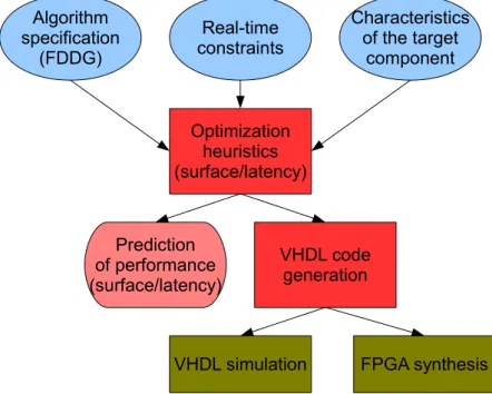
for realistic applications. SynDEx-Ic uses a heuristic based on a greedy algorithm coupled with simulated annealing heuristics. The result of the heuristic is then directly converted into synthesizable VHDL code to run on the target component or to be simulated. Figure 1.4 shows the design flow of SynDEx-Ic.
Algorithm specification (FDDG) Real-time constraints Characteristics of the target component Optimization heuristics (surface/latency) VHDL code generation Prediction of performance (surface/latency)
VHDL simulation FPGA synthesis
Figure 1.4: SynDEx-Ic design flow
SynDEx-Ic needs some libraries to generate the final VHDL code. In addition to the libraries included in the tool, users have to create an application library to define some specific operations by using VHDL. Since the hardware programming in VHDL is usually more complicated than the software programming like in C, we need to search other simpler ways to generate hardware code for hardware/software co-design.
1.3
Tools for HDL Code Generation
Hardware/software co-design usually needs both hardware programming for Intel-lectual Property (IP) coprocessors and software programming for general processors, and the hardware programming is usually more complicated than the software pro-gramming. However, it is possible to generating HDL code from high-level language like C. This section introduces two tools for generating HDL code from high-level languages.
1.3.1
GAUT: A High-Level Synthesis Tool
GAUT (Génération Automatique d’Unités de Traitement)(4) is a high-level
syn-thesis tool developed in Lab-STICC in Lorient (France). It dedicates to Digital Sig-nal Processing DSP applications from an algorithmic specification in C [LGCH+05].
GAUT generates an IEEE P1076 compliant Register Transfer Level (RTL) VHDL file. This file is an input for commercial, off-the-shelf, logical synthesis tools like ISE from Xilinx, Design Compiler from Synopsys, Quartus from Altera, ...
GAUT Design Flow
Figure1.5shows the design flow of GAUT. Starting from a pure C function GAUT extracts the potential parallelism before selecting/allocating operators, scheduling and binding operations. GAUT synthesizes a potentially pipelined architecture composed of a processing unit, a memory unit, a communication and multiplexing unit and a GALS/LIS interface [BMB05, CCB+05,LGCHM05,CSB+04].
Synthesis Constraints: -Data average throughput -System clock frequency
-Memory architecture and mapping -I/O timing diagram (schedule + ports) -FPGA/ASIC target technology Algorithm GAUT GALS/LIS Interface & Communication Unit Memory Unit Controller Data Path Clock enable Req(i) Ack(i) Data(i) Internal buses
Figure 1.5: GAUT design flow
Use of GAUT
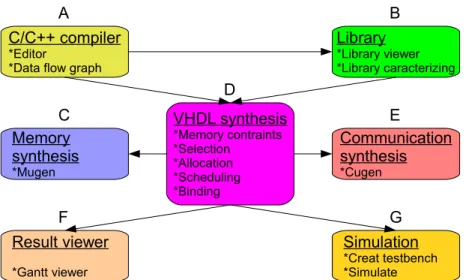
The tool structure in GAUT is shown in Figure 1.6. It mainly consists of seven blocs which are explained as follows:
A: Algorithm analysis, extraction and visualization of parallelism; B: Management of libraries;
C: Generation of Memory Unit (memory banks and associated controllers); D: Synthesis of architecture under constraints of sampling rate;
E: Generation of the communication/protocol interface (FIFO protocol, LIS
inter-face, ...);
F: Visualization of the Gantt chart of the scheduled operations, IOs and memory
access;
G: Generation of the testbench and simulation with ModelSim.
C/C++ compiler *Editor
*Data flow graph
Memory synthesis *Mugen Result viewer *Gantt viewer VHDL synthesis *Memory contraints *Selection *Allocation *Scheduling *Binding Library *Library viewer *Library caracterizing Communication synthesis *Cugen Simulation *Creat testbench *Simulate B A C D E F G
Figure 1.6: GAUT tool structure
The C or C++ code is developed and compiled in the editor window. GAUT com-pilation is a parallelism extraction that allows the creation of the dependency graph file necessary for the VHDL generation. Depending on algorithm specified before the compilation the generated graph contains the necessary computing operators, inputs, outputs and buffers. To generate the VHDL code, GAUT requires specifying a ca-dency, a clock frequency and the type of architecture (with or without memory unit). The VHDL generation depends on the dependency graph and the chosen library. Af-ter VHDL generation, the VHDL testbench can be automatically generated by the
tool. A direct connection between GAUT and ModelSim is possible just by specifying the ModelSim path.
Limits of GAUT
The use of GAUT to transform the C code of an image codec presents some limits of this tool. In fact, GAUT can not deal with very complex C codes. After achieving some tests we noted the following limits:
– GAUT does not support dynamic structures: The C code in the input of the tool must be deterministic which means that all the variable sizes and the treatment length have to be known by the tool. Consequently, it is not possible to compile algorithms containing pointers or while or switch structures.
– Function appeal: We cannot use predefined functions so all functions in the input of the tool must be main ones.
– Preprocessor directives: Some codes contain preprocessor directives used for a DSP compilation. These directives can not be compiled with GAUT, so they have to be eliminated.
– Graphs containing a huge number of knots: If the treatment is very complex and requires a dependency graph with a huge number of knots, the graph generation can not be achieved, and we would not have the VHDL code.
The results obtained by GAUT were not satisfying. The tool, in the 2.2.0 version, was considerably limited to treat complex codes. Even the functions that we succeeded to transform into RTL level VHDL code presented some synthesis problems in Xilinx ISE tool. Some of the synthesized functions contained a big number of states in their FSM and consumed a huge percentage of the FPGA area. Considering these results, we decide to adopt another method for the automatic transformation using the Cal language.
1.3.2
Open Dataflow Framework
Open Dataflow (OpenDF(5)for short) is an environment for building and executing
actor/dataflow models, including support for the Cal actor language. It is also a compilation framework that consists of tools to compile Cal to HDL(VHDL/Verilog) for hardware implementation [JMP+08] and to C for integration with the SystemC
tool chain [RWR+08]. Work on mixed HW/SW implementations is under way.
Cal Language
Cal [EJ03,Jan07] is a domain-specific language that provides useful abstractions for dataflow programming with actors. Cal has been used in a wide variety of ap-plications [LMTJ07]. This section gives a brief introduction to the key elements of actor and network for the Cal language.
Actor: An actor is a parametric entity with inputs, outputs and an internal state. An
actor can not change the state of another actor in the network, but it can com-municate with others by exchanging tokens through connected inputs/outputs. The execution of an actor is based on the execution of elementary functions called actions. The modeling of the actor states can be done using a finite state machine with the appropriate priorities if necessary.
While executing an action some tokens are consumed, and others are produced independently from the current state of the actor. The execution of an action can be controlled by a finite state machine or by a specified condition using the “guard” syntax or both of them. The “guard” is an expression to test the value of an input token or a local variable. If more than one action can be executed at the same time, it is very important to define the priority between them. Therefore, the notion of priority has been introduced in the language. This notion is very important for the finite state machines in case of concurrent actions. The actor functioning can be scheduled using a finite state machine. The required informations are the initial state and the action that changes the current state to the next state.
The basic structure of a Cal actor is shown in the Add actor below, which has two input ports t1 and t2, and one output port s, all of type T. The actor contains one action that consumes one token on each input ports, and produces one token on the output port. An action may fire if the availability of tokens on the input ports matches the port patterns, which in this example corresponds to one token on both ports t1 and t2. actor Add ( ) T t1 , T t 2 ⇒ T s : action [ a ] , [ b ] ⇒ [ sum ] do sum := a + b ; end end
Network: A set of Cal actors are instantiated and connected to form a Cal
Figure 1.7 shows a simple Cal network Sum, which consists of the previously
defined Add actor and a delay actor Z. The network itself has input and output ports, and the instantiated entities may be either actors or other networks, which allows for a hierarchical design. The source code for the delay actor Z and the network Sum is found below as well as the XML description of the network.
Z(v=0) Add Sum B A Out Out Out In In
Figure 1.7: A simple Cal network
actor Z ( v ) I n ⇒ Out : A: action ⇒ [ v ] end B : action [ x ] ⇒ [ x ] end schedule fsm s 0 : s 0 (A) −−> s 1 ; s 1 (B) −−> s 1 ; end end
network Sum ( ) I n ⇒ Out :
e n t i t i e s add = Add ( ) ; z = Z ( v = 0 ) ; structure I n −−> add .A; z . Out −−> add . B ; add . Out −−> z . I n ; add . Out −− > Out ;
end < ? x m l v e r s i o n = " 1.0 " e n c o d i n g = " UTF -8 " ? > < XDF n a m e = " Sum " > < P o r t k i n d = " I n p u t " n a m e = " In " / > < P o r t k i n d = " O u t p u t " n a m e = " Out " / > < I n s t a n c e id = " add " / > < I n s t a n c e id = " z " > < C l a s s n a m e = " Z " / > < P a r a m e t e r n a m e = " v " > < E x p r k i n d = " L i t e r a l " li t er al - k i n d = " I n t e g e r " v a l u e = " 0 " / > < / P a r a m e t e r > < / I n s t a n c e > < C o n n e c t i o n dst = " add " dst - p o r t = " A " src = " " src - p o r t = " In " / > < C o n n e c t i o n dst = " add " dst - p o r t = " B " src = " z " src - p o r t = " Out " / > < C o n n e c t i o n dst = " z " dst - p o r t = " In " src = " add " src - p o r t = " Out " / > < C o n n e c t i o n dst = " " dst - p o r t = " Out " src = " add " src - p o r t = " Out " / > < / XDF >
Formerly, networks have been traditionally described in a textual language, which can be automatically converted to FNL (Functional unit Network Language, XML language standardized in RVC [LMTJ07]) and vice versa. Graphiti editor, which is presented in Section 1.4.1, is available to create, edit, save and display a network.
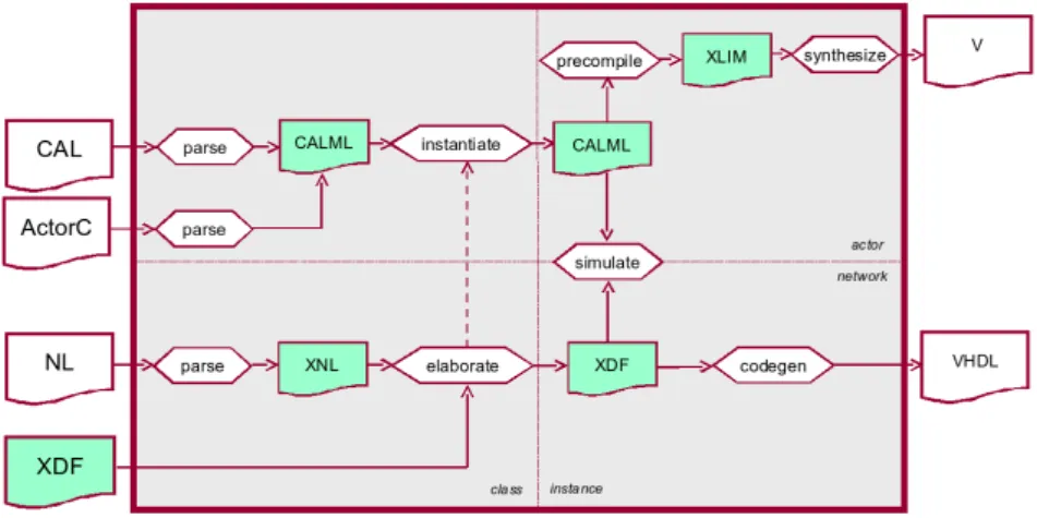
Hardware Synthesis - CAL2HDL
Cal program must be implemented in real systems. Therefore, it should be lated to other technique languages for hardware and software synthesis, and the trans-lation should be automatic. In fact, OpenDF is also a compitrans-lation framework, and there are backends for converting Cal program to HDL and C programs.
Cal program is translated to HDL by using a tool named CAL2HDL [JMP+08]. When generating hardware implementations from a network of Cal actors, each ac-tor is separately translated to RTL description in Verilog, and a number of acac-tor instances that are references of the generated RTL descriptions are connected with FIFOs to elaborate the network structure in VHDL. Figure1.8 shows the CAL2HDL tool structure in OpenDF [Xil08].
Figure 1.8: CAL2HDL tool structure in OpenDF
Cal Simulation
Cal is supported by a portable interpreter infrastructure that can simulate a hierarchical network of actors. This interpreter was first used in the Moses(6) project.
Moses features a graphical network editor, and allows the user to monitor actors’
execution (actor state and token values). The project being no longer maintained, it has been superseded by an Eclipse environment composed of 2 tools/plugins - the OpenDF environment for Cal editing and the Graphiti editor for graphically editing the network.
An Design Example with OpenDF
We give an example of implementing an MPEG-4 Part 2 decoder for intra frames on a FPGA platform from Xilinx. The decoder is expressed as a Cal algorithm, and the top level network is shown in Figure 1.9(a). The decoder consists of one input port, three entities and one output port. The serialize is an entity of actor; the parser is an entity of subnetwork composed of actors; and the decode is an entity of subnetwork composed of other two subnetworks. Figure 1.9(b) shows the two subnetworks acdc and idct2d of the entity decode.
BITS B BTYPE data out VIDEO BTYPE bits in8 out
serialize parser decode
(a) Network of the decoder
BTYPE out signed in out out signed data data BTYPE acdc idct2d (b) Subnetwork of decode
Figure 1.9: Algorithm of MPEG-4 Part 2 decoder
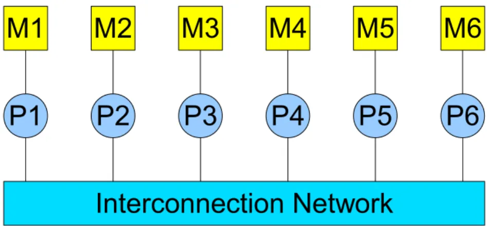
Figure 1.10 shows the architecture of a system containing a computer and an ML402 platform(7) of Xilinx. This system uses the FPGA and the external memory
of the ML402 platform. The FPGA contains a processor of MicroBlaze (uB), an IP (IP1) connected to the MicroBlaze by two FIFOs (FSL1 and FSL2) of FSL, and another IP (IP2) connected to the MicroBlaze by the bus of PLB (Processor Local Bus). The external memory (M) is connected to the MicroBlaze by the bus PLB, and the computer (PC) is connected to the MicroBlaze by the bus TCP with TCP/IP protocol.
PC uB M IP1 TCP PLB FSL1 FSL2 IP2 ML402 FPGA Figure 1.10: Architecture of PC+ML402
The MPEG-4 Part 2 decoder is implemented on the architecture of PC+ML402. The top level network is firstly compiled to threads of SystemC by CAL2C [RWR+08],
then it is manually translated to be executed on MicroBlaze with a POSIX API targeting embedded kernel. The two entities serialize and parser are executed on the MicroBlaze by calling functions, and the entity decode is executed on the coprocessor IP1. IP1 is generated by CAL2HDL [JMP+08], and an additional interface is manually
created and added between IP1 and the two FSLs. The output VIDEO is transferred from IP1 to the external memory M on the platform by the MicroBlaze. VIDEO is finally displayed by IP2, which is a hardware display controller IP core of Xilinx. All these entities are synchronized on the MicroBlaze by using semaphores.
1.3.3
Comparison between GAUT and OpenDF
Though GAUT and OpenDF can both generate HDL code from high level lan-guages, they differ from each other in some aspects. A comparison of these two tools is given as follows:
Criteria GAUT OpenDF
General use The initial C code has to be CAL can be used for both simple, deterministic and with simple and complex a minimum of control structures. Being a high structures. The perfect code level language, the code would be a computing development is relatively algorithm as matrix product, simple.
transforms (Fourier, Laplace, ... ), interpolation, ...
HDL code GAUT offers the possibility The Generated codes are a generation to choose the aspect of the VHDL one for the top file
final structures. If a C code and a Verilog one for each is correctly compiled, the actor. Connections, inputs generated VHDL code is and outputs are transformed synthesizable and correctly into FIFOs synchronized by
simulated. consumption of tokens.
Compilation While compiling a C/C++ The CAL2HDL compilation code, GAUT extracts the is a generation of
parallelism structures and intermediate files that creates a *.cdfg file that enable the HDL code allows the dependency graph generation. These files are generation. This graph is *.xlim, *.sxlim, *.ssacalml used for the VHDL code and *.pcalml.
generation.
Simulation The generated VHDL of The CAL code can be GAUT can be directly simulated before the HDL simulated via a connection code generation. But for between GAUT and hardware simulation, a ModelSim. An adequate testbench has to be written. testbench is automatically
generated.
Limits GAUT can not support OpenDF can not generate HDL dynamic structures, pointers for repeat structures because and non-deterministic an actor is unable to consume
algorithms. more than one token in an
input at a precise time.
1.4
An Eclipse-Based Open Source Rapid
Proto-typing Framework
When we have the hardware/software codes for specific operations, we then need a tool to implement the rapid prototyping methodology for parallel embedded sys-tems. This section introduces an Eclipse-based open source rapid prototyping frame-work. Figure 1.11 shows the framework structure. It is made up of three tools to
increase their reusability in different contexts. The three tools are Graphiti, SDF4J and PREEM; they are detailed as follows.
SDF4J
Core
Scheduler Graph transformation
Code generator Graphiti
Eclipse framework
Rapid prototyping Eclipse plug-ins Generic graph editor
Eclipse plug-in
Dataflow graph transformation java library
uses
Plugs in
Figure 1.11: An Eclipse-based rapid prototyping framework
1.4.1
Graphiti: A Generic Graph Editor for Editing
Archi-tectures, Algorithms and Workflows
The first step of rapid prototyping is to describe the target algorithm and archi-tecture graphs. A graphical editor decreases the development time to create, modify and edit those graphs. Graphiti(8) is an open-source plug-in for the Eclipse
environ-ment and is provided to support algorithm and architecture graphs for the proposed framework. Graphiti can also be quickly configured to support any type of file formats used for graph descriptions.
Graphiti is written using the Graphical Editor Framework (GEF). The editor is generic in the sense that any type of graph can be represented and edited. Graphiti is being used routinely with the following graph types and associated file formats: CAL networks (cf. Section 1.3.2), a subset of IP-XACT (cf. Section 2.3.3), GraphML (cf. Section1.4.2) and PREESM workflows (cf. Section 1.4.3).
Overview of Graphiti
A type of graph is registered within the editor by a configuration. A configuration is an XML (Extensible Markup Language) file that describes:
1. the abstract syntax of the graph: types of vertices and edges, attributes allowed for objects of each type;
2. the visual syntax of the graph: colors, shapes, etc.;
3. the transformations from the file format in which the graph is defined to the XML file format G of Graphiti, and vice-versa (Figure 1.12).
Two kinds of input transformations are supported, from XML to XML and from text to XML (Figure 1.12). Both these transformations are independent from the code of the editor: XML is transformed to XML with XSLT (Extensible Stylesheet Language Transformations), and text is parsed to its Concrete Syntax Tree (CST) represented in XML according to a LL(k) grammar by the Grammatica(9) parser.
Similarly, two kinds of output transformations are supported, from XML to XML and from XML to text.
XML Text XML CST XSLT transformations G parsing
(a) reading an input file to G
G transformationsXSLT
XML
Text
(b) writing G to an output file
Figure 1.12: Input/output with Graphiti’s XML format G
Graphiti handles attributed graphs. According to [JE01], an attributed graph is defined as a directed multigraph G = (V, E, µ) where
– V is the set of vertices;
– E is the multiset of edges (there can be more than one edge between any two vertices);
– µ is a function µ : ({G} ∪ V ∪ E) × A 7→ U that gives the attribute value (from the set of possible attribute values U ) for an instance (from {G} ∪ V ∪ E)) with an attribute name (from the attribute name set A).
A built-in type attribute is defined so that each instance i ∈ {G} ∪ V ∪ E has a type t = µ(i, “type”), and only admits attributes from a set At ⊂ A. Additionally,
a type t has a visual syntax: σ(t) defines the color, shape and size associated with instances of type t.
Editing a graph with Graphiti is done as follows. The user selects a file and a set of matching configurations is computed based on the file extension. If the set contains more than one configuration, Graphiti asks the user which one is suitable for
the input file. The transformations defined in the configuration file are then applied to the input file, which results in a graph defined in Graphiti’s XML format G as shown in Figure1.12. The editor uses the visual syntax defined by σ in the configuration to draw the graph, vertices and edges. For each instance of type t the user can edit the relevant attributes allowed by τ (t) as defined in the configuration. Saving a graph consists in writing the graph in G, and transforming it back to the input file’s native format.
Editing a Configuration for a Graph Type
To create a configuration for the graph in Figure 1.13, a single type of vertex called “node” has to be defined. A “node” has an unique identifier called “id”, and accepts a list of “values” initially equal to [0] (Figure 1.14). Additionally, ports need to be specified on the edges, so the configuration describes an edgeType element (Figure 1.15) that carries “sourcePort” and “targetPort” parameters to respectively store an edge’s source and target ports, such as acc, in, and out in Figure 1.13.
Figure 1.13: A sample graph
Graphiti is a tool totally independent of the PREESM tool. However, it generates workflows, IP-XACT and GraphML files that are the main inputs of PREESM. The GraphML files contain the algorithm description. They are loaded and stored in PREESM by the SDF4J library that is discussed in next section. The architecture description respects the IP-XACT standard. It is more specific than the algorithm description, and no external library is defined for architecture handling.
1.4.2
SDF4J: A Java Library for Algorithm Dataflow Graph
Transformation
An algorithm is described as a Synchronous Dataflow Graph (SDF). The SDF model is a natural solution to describe algorithms with static behaviors [LM87b]. SDF4J(10) is an open source library providing usual transformations of SDF graphs
< v e r t e x T y p e n a m e = " n o d e " > < a t t r i b u t e s > < c o l o r red = " 163 " g r e e n = " 0 " b l u e = " 85 " / > < s h a p e n a m e = " r o u n d e d B o x " / > < s i z e w i d t h = " 40 " h e i g h t = " 40 " / > < / a t t r i b u t e s > < p a r a m e t e r s > < p a r a m e t e r n a m e = " id " t y p e = " j a v a . l a n g . S t r i n g " d e f a u l t = " " / > < p a r a m e t e r n a m e = " v a l u e s " t y p e = " j a v a . u t i l . L i s t " > < e l e m e n t v a l u e = " 0 " / > < / p a r a m e t e r > < / p a r a m e t e r s > < / v e r t e x T y p e >
Figure 1.14: The type of vertices of the graph shown in Figure1.13
< e d g e T y p e n a m e = " e d g e " > < a t t r i b u t e s > < d i r e c t e d v a l u e = " t r u e " / > < / a t t r i b u t e s > < p a r a m e t e r s > < p a r a m e t e r n a m e = " s o u r c e p o r t " t y p e = " j a v a . l a n g . S t r i n g " d e f a u l t = " " / > < p a r a m e t e r n a m e = " t a r g e t p o r t " t y p e = " j a v a . l a n g . S t r i n g " d e f a u l t = " " / > < / p a r a m e t e r s > < / e d g e T y p e >
Figure 1.15: The type of edges of the graph shown in Figure 1.13
in the Java programming language. SDF4J stands for Synchronous Dataflow For Java. This library aims at providing the user with a large choice of easily expandable Dataflow models associated to algorithm transformations and optimizations. The library also defines its own graph representation based on the GraphML [BEH+01]
standard and provides the associated parser and exporter classes.
The SDF4J library defines several Dataflow graph models like SDF graph and Directed Acyclic Graph (DAG). It provides the user with several classic SDF formations like hierarchy flattening, HSDF transformation and SDF to DAG trans-formation. These transformations are explained as follows:
– The hierarchy flattening aims at flattening the hierarchy (remove hierarchy lev-els) at the chosen depth in order to later extract as much as possible parallelism from the designer hierarchical description.
– The HSDF transformation transforms an SDF graph to an Homogeneous SDF graph in which the amount of tokens exchanged on edges are homogeneous (pro-duction = consumption). The HSDF model reveals all the potential parallelism of the application but dramatically increases the amount of vertices in the graph. – The SDF to DAG transformation transforms an HSDF graph to a DAG which
1.4.3
PREESM: A Complete Framework for
Hardware/Soft-ware Co-design
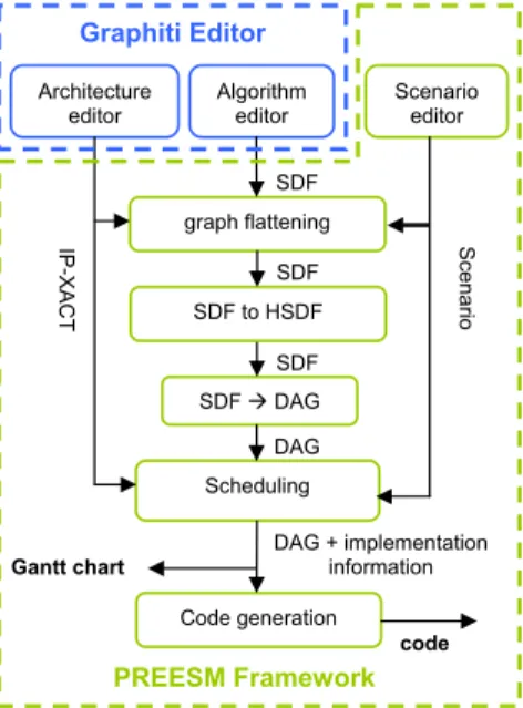
The PREESM [PRP+08] project performs the rapid prototyping tasks. PREESM
uses the Graphiti and SDF4J tools to design algorithm and architecture graphs and generates their transformations. The PREESM core is an Eclipse plug-in that executes workflows. A workflow is a directed graph representing lists of rapid prototyping tasks to be executed with the input algorithm and architecture graphs. The rapid prototyping tasks are delegated to PREESM plug-ins. All these plug-ins are optional and appear as vertices in a workflow graph. PREESM is also built to be easily extensible with new plug-ins. There are three PREESM plug-ins at present: the graph transformation plug-in, the scheduler plug-in and the code-generation plug-in. Figure1.16describes a classic workflow which can be applied in the PREESM tool. As seen in Section 1.4.2, the first dataflow model chosen to describe applications in PREESM is the SDF model. This model has the great advantage of enabling formal verification of static schedulability. The typical number of vertices to schedule in PREESM is between a hundred and a few thousands. The architecture is described based on the IP-XACT standard [SPI08] that is an IEEE standard from the SPIRIT consortium. The typical size of an architecture in PREESM is between a few cores and a few dozens of cores. A scenario is defined as a set of parameters and constraints that specify the conditions under which the deployment will run.
SDF Gantt chart graph flattening SDF DAG Scheduling Code generation Algorithm editor Architecture
editor Scenarioeditor
SDF DAG DAG + implementation information S cenario IP-XACT code SDF to HSDF SDF PREESM Framework Graphiti Editor
Prior to entering in the scheduling phase, the algorithm goes through three steps of transformations: hierarchy flattening, HSDF transformation and SDF to DAG transformation. These transformations prepare the graph for the static scheduling and are provided by the Graph Transformation Module. Subsequently, the SDF graph converted into a Directed Acyclic Graph (DAG) is processed by the scheduler. As a result of the deployment by the scheduler, code is generated and a Gantt chart of the execution is displayed. The generated code consists of well scheduled function calls, synchronizations and data transfers between cores. The functions themselves are hand-written.
1.5
Conclusion
This chapter presented rapid prototyping and hardware/software co-design. AAA rapid prototyping methodology has been used in SynDEx to design multiprocessor embedded systems for many applications like digital signal processing and video com-pression. We used this methodology for multi-MicroBlaze systems on FPGA. Codes are automatically generated for each MicroBlaze with the developed kernels. Hard-ware/software co-design also needs to generate HDL code for hardware coprocessors that is usually more complicated than software code. GAUT and OpenDF are both tools for generating HDL code from high-level languages. The generated HDL code can be synthesized and implemented on FPGA as a complete design or a part of an embedded system.
We presented a new rapid prototyping framework of PREESM that supports hard-ware/software co-design for parallel embedded systems. PREESM firstly models an algorithm and an architecture as graphs, then it schedules the algorithm onto the architecture. The schedule results are finally used to generate code for the multiple processors of the architecture. We will mostly concern the scheduling problem in the following of this work. Therefore, the graph models used for scheduling will be explained in the next chapter. The scheduling problem will be deeply studied in the Chapter 3, 4and 5.
2
Graph Models for Parallel
Embedded Systems
2.1
Introduction
The recent evolution of embedded applications like digital communication and video compression has dramatically increased the algorithm and system complexities. In this work the application algorithm and the target system are respectively called algorithm and architecture. When a complicated algorithm is implemented on a par-allel architecture for efficient computation, graphs [Die05] are usually used to model the algorithm and the architecture in order to facilitate the programming.
An algorithm can be modeled as different types of graph according to the different objectives. Dataflow graph is commonly used and consists in modeling an algorithm as a directed graph of data flowing between operations. Since an algorithm needs to be scheduled on the multiple processors of a parallel architecture, it is modeled as a Di-rected Acyclic Graph (DAG) for task scheduling, where nodes represent computations and edges represent communications between computations.
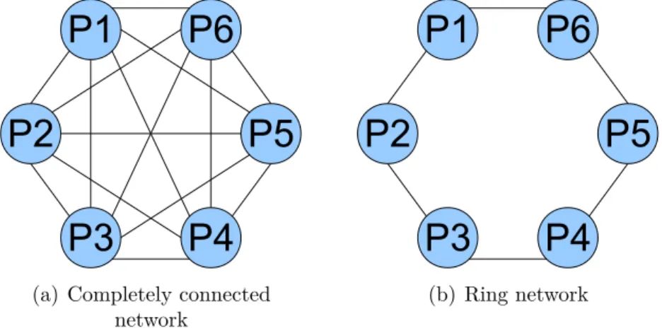
Computer architecture has changed from single-processor systems to parallel sys-tems [Dun90, ERAEB05]. Parallel architectures are classified as the shared mem-ory architecture and the distributed memmem-ory architecture. Parallel computation also needs appropriate models to describe architectures. The first model for the shared memory architecture was the parallel random access machine (PRAM) in [FW78].
Since PRAM is not accurate to describe a real parallel system, some other models were introduced to accurately describe real parallel systems. For example, the LogP model [CKP+93] uses four parameters to roughly describe the parallel system and is a balance between detail and simplicity.
The trend of parallel architecture is also coming in the domain of embedded sys-tems. Parallel embedded systems usually use distributed memory architectures. For performance analysis and estimation, distributed memory architectures are usually modeled as completely connected graphs. However, this completely connected graph model is not yet accurate for parallel embedded systems. In [GS03], a parallel em-bedded system is modeled as an architecture graph containing four kinds of vertices corresponding to operator, communicator, memory and bus. However, this architec-ture graph does not describe advanced components like switches which are commonly used in parallel embedded systems for connecting multiple buses. Therefore, we need a new architecture model to appropriately describe parallel embedded systems.
This chapter introduces different existing algorithm and architecture models and proposes an advanced architecture model. The advanced architecture model will be used in the task scheduling for parallel embedded systems. This chapter is organized as follows: Section 2.2 introduces several graph models for algorithms. Then differ-ent architecture models are given in Section 2.3 including our advanced architecture model. The chapter is concluded in the end.
2.2
Algorithm Model
An algorithm can be modeled in different ways according to different objectives. These models are usually directed graphs, and this section presents some graph models for describing an algorithm.
2.2.1
Dataflow Model
Many applications such as signal processing applications aim to transform data. Systems implementing these applications are data-oriented. They react continuously to their input dataflows and also produce some output dataflows. Dataflow program-ming is commonly used in these systems, and the main objective is to explore the parallelism of an application.
appli-cations. Such applications can be decomposed into a collection of operations that communicate each other, and they are easily represented by graphs. The dataflow model represents a program in a directed graph. Nodes of the graph represent opera-tions to be performed (an instruction or a group of instrucopera-tions), while data flow on edges of the graph and form the input to the nodes. The data are carried by tokens. Dataflow programming is sometimes coupled to functional programming languages in which the operations are evaluated as functions without side effect (no modification of state, no interaction with the outside world) and the output tokens are results of a function by consuming the input tokens.
There are many graph models based on the dataflow principle. Modeling program in this form does not specify the invocation rules of the operations and the techniques to model the communication channels. We present some important models as follows.
Kahn Process Networks (KPN)
Kahn described a simple programming language to model the parallel program-ming for distributed systems at the beginning of 70s [Kah74]. This model is known as Kahn Process Network (KPN). In such a process network, concurrent processes com-municate by asynchronous message passing through unidirectional FIFO channels of infinite capacity. Each FIFO channel carries a sequence of tokens (possibly infinite) that evolve over time. A process is a mathematical function from a set of sequences to another set of sequences. Each token is written exactly once to a channel and is also read exactly once from a channel. Writing to a channel is non-blocking because of the channel’s infinite capacity. However, reading from a channel is blocking, which means a process attempting to read from an empty channel stalls until this channel has sufficient tokens to be read.
A process in the KPN model is usually continuous. The continuity of process is a sufficient condition to ensure the determinacy of process networks. The network is determinate when the execution order of the processes in the network has no influence on the output result. It is shown in [KM77] that the continuity is guaranteed by the blocking reading of the FIFOs in practice.
While KPN was developed to model the concurrency in a program, the dataflow model in [Den74] was initially applied in the development of computer architectures. Operations of a graph are specified by actors in this dataflow model. An actor maps input tokens into output tokens when it fires. A set of firing rules specify when an actor can fire. A firing consumes input tokens and produces output tokens. A sequence of
firings is a particular type of Kahn process and is called a dataflow process [LP95]. A network of such processes is called a dataflow process network and is a particular case of KPN. Some special dataflow process models are presented as follows.
Synchronous Dataflow (SDF)
The Synchronous Dataflow (SDF) was firstly introduced in [LM87a,LM87b]. The SDF model is a special case of the dataflow process model. An actor is a function that fires when there are enough input tokens available to perform a computation (actors-lacking inputs can be invoked at any time). When an actor fires, it consumes a fixed number of new input tokens on each input edge. An actor is said to be synchronous if we can specify a priori the number of input tokens consumed on each input edge and the number of output tokens produced on each output edge each time the actor fires. An SDF actor is a dataflow actor that only contains a single firing rule [LP95]. This firing rule is valid for all possible numbers of tokens. The number of tokens consumed and produced is constant each time the actor fires. An SDF graph is a network of synchronous actors. Figure 2.1 shows an SDF actor and an SDF graph.
a b c (a) a b c h i g d e f (b)
Figure 2.1: (a) An SDF actor; (b) An SDF graph
An SDF graph is well suited to model synchronous multirate signal processing applications. An application modeled by an SDF graph can be scheduled on single or multiple processors. It is known at compile time whether an SDF graph can be scheduled statically (at compile time) or not [LM87a]. When the schedule is determined, the memory usage is also bounded and known at compile time, then actors fire repeatedly during the execution.
Boolean Dataflow (BDF)
Although the SDF model is well suited to represent many parts of an application, it is usually difficult to represent an entire application by this model. For example,
control structures are very common in an application, and the execution of the appli-cation depends on the control input. The Boolean Dataflow (BDF) [Buc93] model is an extension of the SDF model, and it allows modeling a number of control structures by adding some specific control actors. These control actors have the dynamic com-portments. The number of tokens consumed or produced can not be known a priori and depends on the value of an input control token.
SWITCH and SELECT are two control actors in the BDF model as shown in Figure 2.2. The SWITCH actor consumes an input token (A in Figure 2.2(a)) and a control token (S in Figure 2.2(a)). If the control token is TRUE, the input token is copied to the output labeled T; otherwise it is copied to the output labeled F. The SELECT actor performs the inverse operation, reading a token from the input labeled T if the control token is TRUE, otherwise reading from the input labeled F, and copying the token to the output.
SWITCH T F S A B C (a) SWITCH T F SELECT S A B C (b) SELECT Figure 2.2: Control actors: SWITCH and SELECT
The main advantage of the BDF model is that it allows modeling a larger class of programs. In fact, the BDF model is Turing-complete [Buc93], and any algorithm can be expressed in this model in principle. Unfortunately, it has been shown that the use of bounded memory and the presence of deadlocking are indeterminate at the compile time in general for the BDF model.
Dynamic Dataflow (DDF)
Many complex applications (e.g. multimedia) need to make decisions during the execution by concerning the treatment results. Therefore, some operations depend on the value of data (data-dependent). We have seen that the SDF model can be extended to BDF model by adding two dynamic actors of SWITCH and SELECT to
express control structures. Since the BDF model is Turing-complete, it is possible to model all functions that can be defined by an algorithm. Then it is possible to model all complex applications in the BDF model. However, this model is not convenient to express control structures other than structures like if-then-else. For example, a loop can be modeled but requires a really complex graph. The Dynamic Dataflow (DDF) model is then presented to facilitate the expression of control structures. This model may contain dynamic actors in addition to SWITCH and SELECT of the BDF model. They can consume and/or produce variable number of tokens according to their input tokens.
The DDF network is the most general dataflow process network. Thus the SDF and BDF models are special cases of the DDF model. Since a dataflow process network is a particular case of KPN, the containing relation of these four dataflow models is shown in Figure 2.3.
KPN DDF BDFSDF
Figure 2.3: Containing relation of different dataflow models
The dataflow model is usually used to represent an application algorithm for pro-gramming. When this algorithm is implemented on a multi-processor system, schedul-ing is needed to assign operations on different processors of this system. In fact, we usually use another graph model to describe the algorithm for the scheduling problem. This model is called the DAG model and is explained in the next subsection.
2.2.2
DAG Model
DAG model is usually used to represent an algorithm for task scheduling. There-fore, a DAG is also called a task graph and is defined as follows.
DAG
A DAG is a directed acyclic graph G = (V, E, w, c) where V is the set of nodes and E is the set of edges. A node represents a computation. For a pair of nodes (ni, nj) ∈ V2, eij denotes the edge from the origin node ni to the destination node