Science Arts & Métiers (SAM)
is an open access repository that collects the work of Arts et Métiers Institute of
Technology researchers and makes it freely available over the web where possible.
This is an author-deposited version published in: https://sam.ensam.eu
Handle ID: .http://hdl.handle.net/10985/8584
To cite this version :
Hussain NOURI, Florent RAVELET, Christophe SARRAF, Farid BAKIR - Experimental study of blade rigidity effects on the global and the local performances of a thick blades axial-flow fan - In: ASME 2010 3rd Joint US-European Fluids Engineering Summer Meeting collocated with 8th International Conference on Nanochannels, Microchannels, and Minichannels, Canada, 2010 -Proceedings of the 3rd Joint US-European Fluids Engineering Summer Meeting and 8th International Conference on Nanochannels, Microchannels, and Minichannels - 2010
Any correspondence concerning this service should be sent to the repository Administrator : archiveouverte@ensam.eu
Experimental study of blade rigidity effects on the global and local
performances of a thick blades axial-flow fan
Hussain Nouri, Florent Ravelet, Christophe Sarraf, and Farid Bakir
Arts et Metiers ParisTech, DynFluid, 151 boulevard de l’Hˆopital, 75013 Paris, France.
(Dated: Proceedings of 3rd Joint US-European Fluids Engineering Summer Meeting,) (Gust 1-5 2010, Montreal, Canada,)
(DSM-ICNMM2010-30623)
An experimental investigation on the aerodynamic performances of thick blades axial-flow fans was carried out in this study. Two fans are considered, the first one is rotomoulded (in plastic) and the second one is milled (in aluminium). Both have exactly the same shape, except that the rotomoulded fan has hollow blades. They were designed from an existing fan (manufactured by plastic injection process) used in the cooling system of an automotive vehicle power unit. As far as shape is concerned, the only difference between the two first fans and the traditional injected fan is the blade thickness, whereas as far as rigidity is concerned, the only difference between the rotomoulded and the milled fans is the ability of the rotomoulded fan to be deformed easier than the milled fan.
The aim of this study is to determine on the one hand the influence of the blade thickness and on the other hand the way the deformation of the hollow blades may affect the global and the local performances.
The global performances of the fans were measured in a test bench designed according to the ISO 5801 standards. The curve of the aerodynamics characteristics (pressure head versus flow rate) and of the global efficiency are slightly lower for the rotomoulded fan. The wall pressure fluctuations were also investigated for three flow rates: one corresponding to the maximum efficiencies of both fans and the two others corresponding to an under-flow and an over-flow rate. The power spectral density (PSD) levels, are between six and nine times higher for the rotomoulded fan at nominal flow rate. At partial flow rate, however, the PSD levels are close for both fans.
NOMENCLATURE
Roman characters qv [m3· s−1] flow rate
c [m] Chord length
x/c [-] Relative chord wise location f [Hz] frequency
D [mm] Ducting pipe diameter
Ps [W] Electric power supplied to the shaft
Greek characters
η [-] Efficiency ω [rad.s−1] Angular velocity φ [-] Flow coefficient Ψ [-] Pressure coefficient γ [o] Stagger angle
∆p [Pa] Pressure rise Subscripts
ext External
int Internal
bpf Blade passing frequency
Max Maximum
I. INTRODUCTION
The present study is part of a research project that intends to propose a cost-effective axial-fan manufactur-ing solution for small series production. In fact, the usual manufacturing process by plastic injection is
cost-effective only for mass production series (> 10000 pieces). The rotomoulding process [1] on the contrary has the advantage of being cost-effective even for small series ( between 100 and 1000 pieces). However, in comparison with plastic injection fans, the rotomoulded fans blades present three major drawbacks.
First, the blades are hollow in a rotomoulded fan and blade surfaces at the hub and the shroud level are open. The potential flow circulation through the blades could affect the fan perfomances, especially regarding the noise generation. Second, as a consequece of hollow blades, the rotomoulded fan has thicker blades which could change the initial fan design and thus the expected performances. One could notice that changing the blade thickness has been used for many years, in aeronautics and the auto-motive industry, as an efficient way to modifiy the lift and drag characteristics [2, 3], and the boundary layers detachment process [4]. The question is whether the ex-tra thickness, in this case when applied to low-speed axial fans, increases the power of the elementary noise sources. Finally, the rotomoulded fan is more and less de-formed according to the angular velocity which again could change the initial design.
Therefore, the aim of this project is to determine the effects of the three points enumerated above on the global performances of the axial fans, and on the pressure fluc-tuations which occur in their wake. The study is carried out in three steps:
In the first step, only the blade thickness aspect is ex-amined by using a rigid fan which has exactly the same
hal-00505858, version 1 - 3 Sep 2012
2 shape as the rotomoulded one, but made in aluminium,
and was specially manufactured for this study. Its per-formances are compared with those of a reference fan that is made in aluminium and has thin blades. This study is presented in [5]. The conclusions of this study indicate that the global performances were substantially equivalent, with a drop of 8% of pressure elevation at conception flow rate for the thick blades fan and a max-imum efficiency that is lower than the efficiency of the thin blades and that is shifted towards lower flow rates. The design point can be reached by a relative increase of rotational speed of 4% with the same power consump-tion. The spectral content of wall pressure fluctuations measured in a ducted-flow configuration is richer for the thick blades fan but the total level of pressure fluctua-tions is lower.
In the second step, the open surfaces at the blades shroud are closed for the rotomoulded fan and its per-formances are compared with those from the thick-blade milled fan. In this step, only the effects of the fan defor-mation are considered.
In the last step, the rotomoulded fan with open sur-faces at the shroud level is tested and the new measure-ments are compared with those from the close-surface rotomoulded fan and from the milled fan.
In each step, the global characteristics are examined (efficiencies and pressure coefficients vs. flow coefficients curves) as well as the wall pressure fluctuation spectra. The present paper presents the results obtained in the last two steps enumerated above: the comparison of the aluminium and the rotomoulded thick-blade fans.
II. EXPERIMENTAL SETUP
A. Geometry of the two tested axial-flow fans
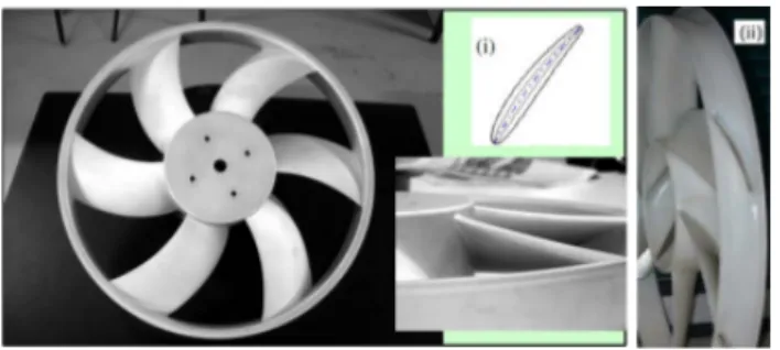
FIG. 1. Views of the thick blades fan. (i): Section of the thick and thin profiles. (ii): Rotomoulded fan with hollow blades
The fans used in this study are two prototypes devel-oped for automotive engine cooling system application following the methods detailed in [6–8]. The fans have exactly the same geometrical characteristics with thick blades, one is rotomoulded and in plastic and the second is milled and in aluminium. Pictures of both fans are shown in Figure 1.
Each of these fans has six blades.The hub-to-tip ra-dius ratio is Rint/RM ax = 0.337 with the tip radius RM ax = 179 mm. The rotor is built up from blades of circular-arc camber lines, with NACA4-digits-based pro-files clipped at 0.95x/c. The maximum blade thickness is 10 mm (whereas for the axial-flow thin blade fan is 4 mm). The blades are swept forward in order to in-crease the efficiency of the fan. Fukano et al. [9] have shown that fans with forward swept blades are superior to those with backward swept blades in terms of global and acoustical performances.
B. Ducted-flow experimental facility
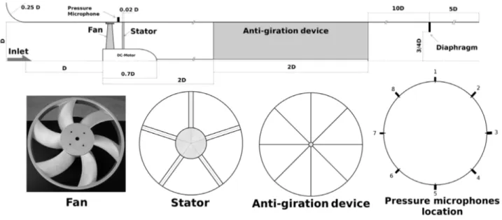
In order to compare the behaviour of the two fans in a ducted-flow configuration, a test bench was built accord-ing to the ISO-5801 standards [10], Figure 2. It consists of a cylindrical pipe of inner diameter D= 380mm. A bell mouth is flushmounted at the inlet of the duct. The upstream face of the fan is at a distance D from the pipe inlet. A DC-motor is hidden in a casing of diameter 0.3D and length 0.7D, with a warhead-shape end. The binding to the tube is ensured by five rods of diameter 8mm, i.e. 0.02D, in order to minimize their influence, regardless the flow rate. The distance between the upstream face of the fan and the binding rods is 0.26 D. An anti-gyration de-vice made of eight metal sheets of thickness 1.5mm and length 2D is placed 2D downstream of the rotor-stator set. It prevents the outgoing flow from having any ro-tating component. The static pressure of the axial fan is measured 1D downstream of the anti-gyration device, with an average over four flush-mounted pressure taps. The flow rate is measured with a normalized diaphragm, located 10D downstream of the anti-gyration device and 5D upstream of the pipe outlet. The diaphragm has a diameter of 0.73D. Other diaphragms of various sizes are placed at the exit of the pipe to vary the test-bench hydraulic impedance and thereby to vary the operating point of the studied axial-flow fan. Wall pressure fluctua-tions are measured simultaneously by eight microphones that are evenly distributed on the circumference of the duct. They are mounted downstream of the fan, halfway between the fan and the five rods that ensure the bind-ing to the tube (see Figure 2). The microphones are G.R.A.S 40BP 1/4” polarized pressure microphones of sensitivity 1.65mV.Pa−1 , with G.R.A.S 26AC pream-plifiers and a G.R.A.S 12AG power supply module. The signals are amplified with a gain of +30 dB and high-pass filtered with a three-pole Butterworth filter with cut-off frequency of 20Hz. The signals are then digitalized using a NI Data Acquisition Card (M6211, 16bits) at a sample rate of 12kHz.
FIG. 2. Ducted-flow configuration dedicated to global and local measurements
III. FAN GLOBAL CHARACTERISTICS
A. The influence of deformation on the rotomoulded fan
In this section, only the deformation of the roto-moulded fan is examined. Therefore, the open surfaces at the blades shroud were closed by rolling up scotch-tape all around the fan.Thus the potential effect of hol-low blades is not taken into account. The characteristics and the efficiencies of the milled fan and the rotomoulded fan (with closed surfaces) are shown in Figures 3 and 4. Flow coefficient (φ) and pressure coefficient (ψ) are de-fined respectively by equation (1) and (2):
φ = qv πωR3 M ax (1) Ψ = ∆p πω2R2 M ax/2 (2)
The efficiency is defined by equation (3): η = ∆p qv
Ps
(3) The curves are the results of six measurements pro-ceeded at ω = 157 rad.s−1(1500 RPM).The three curves have the same shape. The nominal flow rate is the same (φ = 0.15) but the rotomoulded fan produces less depres-sion than the milled fan, particularly at nominal flow rate where this difference reaches its maximum.
Clearly, the deformation of the rotomoulded fan affects significantly the pressure elevation of the fan. The maxi-mum difference observed between both curves is about 6% at nominal operating point. On the other hand,
the efficiency of the rotomoulded fan, with closed sur-faces, is not so much affected. Specially, at partial flow, both curves stick well together until the operating nomi-nal zone where the efficiency of the rotomoulded fan de-creases by 1% whate is still acceptable.
One could notice that increasing the speed rotation by 6.67% allows to reach the curve of the milled fan.
FIG. 3. Fan characteristics: pressure coefficient Ψ vs. flow coefficient φ. ∗: milled fan, +: rotomoulded with closed sur-faces fan, o: rotomoulded with open sursur-faces fan
B. the effect of hollow blades
In this section, the hollow blades are kept open and the influence of the potential flow circulation inside the
4
FIG. 4. Fan characteristics: fan efficiency η vs. flow coeffi-cient φ. ∗: milled fan, +: rotomoulded with closed surfaces fan, o: rotomoulded with open surfaces fan
FIG. 5. Fan characteristics: electric power consumption vs. flow coefficient φ. ∗: milled fan, +: rotomoulded with closed surfaces fan, o: rotomoulded with open surfaces fan
blades is investigated. The characteristics and efficien-cies, in this configuration are also plotted in Figures 3 and 4.
The characteristic curves of the rotomoulded fans with open and closed blades stick well together, particularly at overflow rates. So, one could conclude that there is no effect of closing the open surfaces. But, surprisingly the influence of closing the open surfaces appears on the efficiencies curves. The efficiency of the open surfaces fan is very low comparing to the other two curves al-though the fact that the open and closed surfaces fans have the same characteristics. Considering the definition of the efficiency, the electric power consumption curves were plotted for each case in Figure 5. These curves show that the power consumption of the rotomoulded fan with open surfaces is higher than the two other fans at par-tial flow rate, and at overflow rate it is the milled fan
which has the highest power consumption. Particularly, the power consumption of the closed surfaces fan is the lowest one among the three fans. This fact explains why the efficiency of the closed surfaces fan is so close to the efficiency of the milled fan. But the question is why the power consumption of the rotomoulded fan with closed surfaces is the lowest ?
From this global investigation and as a first conclu-sion, the rotomoulded fan shows promising possibilities. Some points have to be reviewed, in particular closing the hollow blades and making the fan more rigid by using an-other material which is conceivable with the rotomould-ing process. We also intend to measure the deformation with high-speed imaging.
IV. PRESSURE FLUCTUATION
This section presents the measurements of the pres-sure fluctuation at the wall casing of the rotors’ shroud. The three fans considered in this section are the same as above: the milled fan and the rotomoulded fans (with open and closed blades surfaces). For each fan, the wall pressure fluctuations were measured at three different flow rates: partial flow, nominal flow and overflow rates. All measurements were performed at ω = 157.08 rad.s−1 (1500 RPM) during 10 seconds corresponding approxi-matly to 250 fan rotations, and sampled at 12 kHz. Then, the recorded signals were treated with matlab using the modified welch-average Fourier Transform and the ob-tained spectra S(f) are an average of seven 50% overlap-ping parts, windowed with a Hann window. The spectra S(f) are expressed in dB using the formula:
S(f ) = 20 log10p 0(f ) p0
(4)
A. At nominal flow rate φ = 0.15
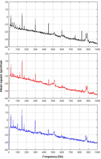
The spectra of wall pressure fluctuations at nominal flow rate are displayed in Figure 6. The three fans ex-hibit relatively high discrete peaks, corresponding to the blade passing frequency fbpf (150 Hz) and its harmon-ics. As expected, the rotomoulded fan with open surfaces has the highest peaks. Only the fundamental and the two first harmonics, 2fbpf and 3fbpf, can be identified on the rotomoulded fans (both open and closed surfaces). The level of the fundamental for the open surfaces roto-moulded fan is 13.73dB, -1.34 dB for the harmonic 2fbpf and -12.43 dB for the harmonic 3fbpf, whereas the closed surfaces rotomoulded fan fundamental is 10.9 dB and its first harmonic reachs -6.7 dB and the second harmonic -14.5 dB. A little decrease is observed when the hollow surfaces at the shroud level are closed.
On the other hand, the spectrum of the milled fan shows the fundamental and the four first harmonics. The
FIG. 6. Square amplitude spectra of wall pressure fluctu-ations at nominal flow rate φ = 0.15. Milled fan (black), rotomoulded with closed surfaces fan (red) and rotomoulded with open surfaces fan (blue)
fundamental reaches no more than 5.0 dB. Table 1 sum-marizes these results.
fbpf 2fbpf 3fbpf 4fbpf 5fbpf
Milled fan 5 −2.98 −8.55 −17.38 −24.77 Rotomoulded, closed 10.9 −6.7 −14.5 − −
Rotomoulded, open 13.73 −1.34 −12.43 − − TABLE I. Fundamental and harmonics peak values at nomi-nal flow rate φ = 0.15, in dB
Globally, both rotomoumded fans could be considered as similar. Their spectra reveal the fundamental and the two first harmonics with realtively high peaks. As for the milled fan, its spectrum reveals more harmon-ics, four, but generally with lower peaks than the roto-moulded fans.
In particular, all fans show in their spectra a peak at f=24.9 Hz. This frequency corresponds to the
rota-tion frequency (1500 RPM/ 60 s). This fundamental could have till six harmonics, depending on the signals recorded. This frequency indicates that either the fan is mounted unbalanced or the deformation creates a dy-namic unbalance generating this frequency. It was ob-served, that for rotomoulded fans, which are more de-formed than the milled fan, the peak values are more important. This increase could be explained by a more important dynamic unbalance on the rotomoulded fans as a consequence of the fan deformation.
B. At partial flow rate φ = 0.09
FIG. 7. Square amplitude spectra of wall pressure fluctuations at partial flow rate φ = 0.09. Milled fan (black), rotomoulded with closed surfaces fan (red) and rotomoulded with open surfaces fan (blue)
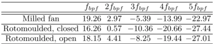
The spectra at partial flow rate (Figure 7) are similar to those from the nominal flow rate with differences only in their peak levels. Surprisingly, the fundamental of the milled fan has the maximum value of 19.29 dB, followed by the fundamental of the open surfaces rotomoulded fan which reaches 18.15 dB and eventually, the closed surfaces rotomoulded fan which reaches 16.26 dB what
6 is the lowest peak among all peaks. Table 2 shows the
fundamental and their harmonics at partial flow.
fbpf 2fbpf 3fbpf 4fbpf 5fbpf
Milled fan 19.26 2.97 −5.39 −13.99 −22.97 Rotomoulded, closed 16.26 0.57 −10.36 −20.66 −27.44 Rotomoulded, open 18.15 4.41 −8.25 −19.44 −27.01 TABLE II. Fundamental and harmonics peak values at partial flow rate φ = 0.09, in dB
According to Table 2, at partial flow, the rotomoulded fans’ harmonics are amplified. The rotational speed fre-quency and its harmonics are still observed but only for the rotomoulded fans at partial flow rate, implying same conclusions as before.
C. At over-flow rate φ = 0.20
FIG. 8. Square amplitude spectra of wall pressure fluctua-tions at over-flow flow rate φ = 0.20. Milled fan (black), rotomoulded with closed surfaces fan (red) and rotomoulded with open surfaces fan (blue)
At over-flow rate the peaks level globally decreases (Figure 8). The spectrum of the milled fan still shows more harmonics than the other spectra but with lower peak height for the fundamental and for the first har-monic. From the second harmonic, the peaks level is lower for the rotomoulded fan with open surfaces, Table 3. Regarding the rotomoulded fan with closed surfaces, it was observed that the second harmonic disapeared from the spectrum.
fbpf 2fbpf 3fbpf 4fbpf 5fbpf
Milled fan 0.54 −1.61 −5.77 −13.83 −22.01 Rotomoulded, closed 0.68 − −15.03 −20.44 −26.25
Rotomoulded, open 7.88 −0.59 −9.05 −17.67 − TABLE III. Fundamental and harmonics peak values at over-flow over-flow rate φ = 0.20, in dB
V. CONCLUSION
This experimental study allowed to better understand the effects of blade rigidity on fans used in the cooling system of an automotive vehicle power unit. The consid-ered configurations were: a milled fan in aluminium, a rotomoulded fan with hollow blades and the same hollow blade fan but with closed surfaces at the shroud level. All of these fans have exaclty the same shape and the same thickness but differ by their material (aluminium and plastic). The study was divided into two parts:
The global characteristics investigation of each fan showed that a maximum drop depression of 6% is ob-served between the milled fan and the rotomoulded one at nominal flow rate. It also showed that closing the open surfaces at the shroud does not change that much the pressure head of the rotomoulded fan. The most an-noying point is the deformation of the rotomoulded fan during operation. But this problem could be solved by using a more rigid material.
The second part of this study was about the local pres-sure fluctuations at the wall casing. Three flow rates were investigated and used to compare the two fans: At par-tial flow rate, nominal flow rate and over-flow rate. Then, the PSD of each measurements were displayed using the modified welch-average Fourier Transform. Even if any conclusion about the acoustical matter of the fan can not be drawn, the peak values are lower for the milled fan. The deformation of the rotomoulded fan in operat-ing could explain these high peaks.
Despite these small drawbacks of the base rotomoulded fan, they have encouraging global performances. Solu-tions that give more rigidity to the blades have to be tested. On the long term, there is good hope that the rotomoulding process replaces the usual plastic injection process for small series.
Further investigations are needed to better understand the effects of the blades thickness. Finite element analysis
of the full wheel will be carried out to see the amplitude of mode shapes. Also, local LDV and PIV measurements and numerical simulations will be performed in order to highlight flow separation process, unsteadiness around fan blades and wake interactions.
These measurements will be used as a benchmark for high-order finite volume CFD codes developed for aeroa-coustics in the laboratory, and data are also available on request.
VI. REFERENCES
[1] Tcharkhtchi, A., 2004. ”Rotomoulding of thermo-plastic parts”. Techniques de l’Ing´enieur — Plastiques et Composites, AM4(AM3706), pp. AM3706.1–15.
[2] Thwaites, B., 1985. Incompressible Aerodynamics, An acount of the Theory and Observation of the steady Flow of incompressible Fluid past Aerofiles, Wings, and Other Bobies. Hoerner Fluid Dynamics.
[3] Hoerner, S. F., 1987. Fluid-Dynamic Lift. Dover Publication Inc.
[4] Sarraf, C., Djeridi, H., and Billard, J., 2008. ”Ef-fets d’´epaisseur et couche limite sur profil portant. Effets de l’´epaisseur des profils naca sym´etriques sur leurs per-formances et l’´etat de la couche limite turbulente”. Eu-ropean Journal of Environmental and Civil Engineering,
12(5), pp. 587–599.
[5] Sarraf, C., Ravelet, F., Nouri, H., and Bakir, F., 2010. ”Experimental study of blade thickness effects on the global and local performances of axial-flow fans”. In 7th International Conference on Heat Transfer, Fluid Me-chanics and Thermodynamics, Antalya, Turkey, pp. 1428 http://hal.archives–ouvertes.fr/hal–00453101/.
[6] Noguera, R., Rey, R., Massouh, F., Bakir, F., and Kouidri, S., 1993. ”Design and analysis of axial pumps”. In ASME Fluids Engineering, Second Pumping Machin-ery Symposium, Washington, USA, pp. 95–111.
[7] Bakir, F., Rey, R., and Moreau, S., 1999. ”Latest developments in automotive engine cooling fan systems rotor-stator interactions”. In FEDSM99-7331, San Fran-cisco, USA, p. 7331.
[8] Bakir, F., Moreau, S., Rey, R., Henner, M., and Borg, V., 2003. ”Experimental aeroacoustic analysis of efficient automotive engine cooling fan systems”. In Fan Noise 2nd Int. Symp., Senlis, France, p. 18.
[9] Fukano, T., Kodama, Y., and Takamatsu, Y., 1978. ”Noise generated by low pressure axial flow fans, iii: Ef-fects of rotational frequency, blade thickness and outer blade profile”. Journal of Sound and Vibration, 56(2), pp. 261–277.
[10] 5801, I., 2007. Industrial fans Performance testing using standardized airways. International Standards for