Virtual testing of metallic inserts for sandwich structures
Texte intégral
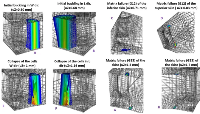
Figure
![Figure 1. Insert’s description of type 1, 2, 3 and testing set up. [10]](https://thumb-eu.123doks.com/thumbv2/123doknet/12255298.320378/3.893.109.783.318.603/figure-insert-s-description-type-testing-set.webp)
![Figure 3. Comparison of the experimental Bunyawanichakul’s curves [10] and the curves used as reference for this research](https://thumb-eu.123doks.com/thumbv2/123doknet/12255298.320378/4.893.165.728.830.1089/figure-comparison-experimental-bunyawanichakul-curves-curves-reference-research.webp)
![Figure 4. Behavior laws of the honeycomb far and near to the insert. (based in [9])](https://thumb-eu.123doks.com/thumbv2/123doknet/12255298.320378/5.893.146.746.527.793/figure-behavior-laws-honeycomb-far-near-insert-based.webp)

Documents relatifs
In particu- lar, if the multiple integrals are of the same order and this order is at most 4, we prove that two random variables in the same Wiener chaos either admit a joint
(a) Appraising Japan’s transport safety regulatory practices with regard to the requirements of the Regulations for the Safe Transport of Radioactive Material (the
Quanti fication of epidermal DR5:GFP reflux signals (Figure 2F; see Supplemental Figure 1 online) con firmed slightly reduced basipetal re flux for twd1 (Bailly et al., 2008)
[r]
L’archive ouverte pluridisciplinaire HAL, est destinée au dépôt et à la diffusion de documents scientifiques de niveau recherche, publiés ou non, émanant des
Particular attention will be given to the effect of valence on the enthalpy of mixing in terminal solutions of group B metals, and to the general problem of the excess
L’archive ouverte pluridisciplinaire HAL, est destinée au dépôt et à la diffusion de documents scientifiques de niveau recherche, publiés ou non, émanant des
We observed from tongue contour tracings that the Mid Bunched configuration generally has a lower tongue tip than the Front Bunched one in speakers who present both bunched
