HAL Id: hal-00876171
https://hal.inria.fr/hal-00876171
Submitted on 23 Oct 2013
HAL is a multi-disciplinary open access
archive for the deposit and dissemination of
sci-entific research documents, whether they are
pub-lished or not. The documents may come from
teaching and research institutions in France or
abroad, or from public or private research centers.
L’archive ouverte pluridisciplinaire HAL, est
destinée au dépôt et à la diffusion de documents
scientifiques de niveau recherche, publiés ou non,
émanant des établissements d’enseignement et de
recherche français ou étrangers, des laboratoires
publics ou privés.
3D view synthesis with inter-view consistency
David Wolinski, Olivier Le Meur, Josselin Gautier
To cite this version:
David Wolinski, Olivier Le Meur, Josselin Gautier. 3D view synthesis with inter-view consistency.
ACM Multimedia, Oct 2013, Barcelone, Spain. �hal-00876171�
3D view synthesis with inter-view consistency
David Wolinski
[email protected]
[email protected]
Olivier Le Meur
[email protected]
Josselin Gautier
University of Rennes 1 - IRISA Campus de Beaulieu 35042 Rennes, France
ABSTRACT
In this paper, we propose a new pipeline to synthesize virtual views. It allows us to generate virtual views far away from each other, each presenting the exact same level of quality. This inter-view consistency is key to seamlessly navigate be-tween viewpoints. Its computational cost is also lower than that of existing approaches. We compare the proposed ap-proach with state-of-the-art methods and show the effective-ness of this new view synthesis pipeline.
Categories and Subject Descriptors
I.4.9 [Image Processing and Computer Vision]: Appli-cations
Keywords
DIBR, FVV, 3DTV, view synthesis
1.
INTRODUCTION
Virtual view synthesis consists in generating a new view-point from existing camera viewview-points. The most popular technique to synthesize virtual views is the Depth Image Based Rendering which relies on the depth information and allows to freely navigate in a scene. This application is called Free-Viewpoint Video (FVV) where virtual views are inter-polated between two known ones [6] or extrainter-polated from one reference view. Unfortunately, DIBR methods suffer from several problems such as the recovery of disoccluded areas. Most of the time, an inpainting method is used to fill-in these areas. For fill-instance, Daribo et Pesquet-Popescu [2] extended Criminisi’s algorithm [1] by modifying the priority function and the patch matching criteria. Gautier et al. [3] also modified Criminisi’s approach by taking into account a direction of filling, depending on the projection direction. Ma et al. [4] proposed a depth-guided inpainting using a new priority scheme and a background-foreground separa-tion technique. Sun et al. [5] proposed a new framework using a joint optimization of inter-view texture similarity
Permission to make digital or hard copies of all or part of this work for personal or classroom use is granted without fee provided that copies are not made or distributed for profit or commercial advantage and that copies bear this notice and the full citation on the first page. To copy otherwise, to republish, to post on servers or to redistribute to lists, requires prior specific permission and/or a fee.
WOODSTOCK’97 El Paso, Texas USA
Copyright 20XX ACM X-XXXXX-XX-X/XX/XX ...$10.00.
and geometry preservation. All these approaches provide new advances in view synthesis methods. However, they all overlook an important aspect which is the consistency be-tween virtual views.
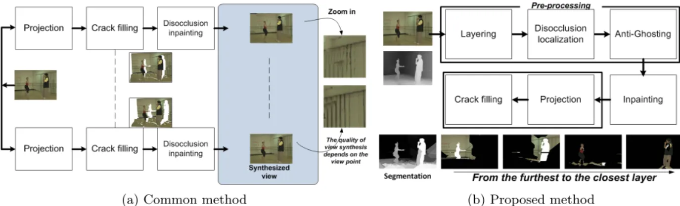
The goal of the presented work is to improve the quality of synthesized views in a context of FVV. Unlike for Zitnick et al. [6], virtual views are here extrapolated from one reference view (one texture image and its depth map).Traditionally, this is performed in the following order: (i) view projec-tion which leads to cracks and disocclusions, (ii) crack fill-ing which usually uses neighborfill-ing data and, finally, (iii) inpainting which aims to fill the disocclusions. We argue that the traditional pipeline, as illustrated in figure 1 (a) suffers from four main issues which essentially cripple the inpainting algorithms.
The first issue is foreground/background differentiation where inpainting algorithms are tempted to use foreground data when filling background disocclusions, leading to very disturbing “spillings”. Moreover, as objects found in the scene don’t always have the same edges on the texture and depth images, after projection, some foreground pixels can end up on the background and vice-versa. This “ghosting” further complicates the inpainting algorithm’s job.Heuristics have been imagined, strengthening the inpainting algorithm but the problem, though minimized, largely persists.
The second issue is data corruption, which degrades the inpainting before it even started. This is caused by the in-painting algorithm using post projection, post crack-filling data.
The third issue concerns the lack of consistency between virtual views synthesized from the same reference view (as il-lustrated by the quality of local regions in figure 1 (a) right). For instance, a disocclusion that is visible in several virtual views is inpainted separately in each of these views. Since the point of view is not the same, this disocclusion is in-painted with differing data, producing different results which are immediately noticeable.
The fourth, last, issue lies with performance while synthe-sizing several views, when as mentioned, the inpainting step is done separately for each view. This not only introduces inconsistencies but is also redundant in that a disocclusion is inpainted once for each time it appears in a virtual view. We aim to solve these issues, regardless of the inpainting algorithm that is used by essentially reversing the classical order of operations required to synthesize virtual views (fig-ure 1 (b)). The overall idea is to inpaint the disoccluded areas before projection automatically removing any redun-dancy as each disocclusion is inpainted only once and also
(a) Common method (b) Proposed method
Figure 1: (a) Common method to synthesize a virtual view. First, the original view is projected. Second, disocclusions and cracks are inpainted. (b) Proposed method to synthesize virtual views - reversed order.
guaranteeing consistency between synthesized views. The data the inpainting algorithm uses is also free of any projec-tion errors or cracks. Finally, we locate future disocclusions on the corresponding backgrounds separate from the fore-grounds, allowing anti-ghosting and avoiding “spillings”.
The paper is organized as follows. In section 2, the pro-posed pipeline is presented. Section 3 shows its performance and a comparison with state-of-the-art results. Conclusions are drawn in section 4.
2.
PROPOSED METHOD
The proposed approach is composed of three main sequen-tial operations (pre-processing, inpainting and projection) described in the following sections.
2.1
Pre-processing
First, the pre-processing projects the reference view into the extreme views in order to detect the largest possible dis-occlusions. With this information, we can then separate the various foregrounds and backgrounds into layers and apply any necessary anti-ghosting.
Depth-based segmentation: The first step is a depth-based segmentation which looks for pixels that are separated by a disocclusion and regroups pixels that remain connex af-ter projecting into extreme virtual views (furthest from the reference view). The goal being to detect disocclusions, it is appropriate to use an edge-based segmentation of the depth map. Moreover, disocclusions should only appear between layers, meaning that the edges of our segmented depth map are the borders of the disocclusions. We thus define disoc-clusions as a loss of connexity between two pixels (p, p0) after projection (P roj): ∀p, p0∈ Image, {p, p0} ∈ IEP if f
p0∈ neighbors(p) ∧ dist(P roj(p), P roj(p0
)) > ∆ Two pixels which lose their connexity (edge-pixels) form an inter-exclusive pair (IEP ): they are on each side of a fu-ture disocclusion and one of them is part of the correspond-ing foreground while the other is part of the correspondcorrespond-ing background (see figure 2 (left)). Then, these edge-pixels are regrouped into regions which do not contain any inter-exclusive pairs (see figure 2 (middle)). All that remains to be done now is to assign all remaining pixels to one of these regions (see figure 2 (right)).
Layering: The depth-based segmentation leads to an over-segmented map. Indeed, some regions are separated by inter-exclusive pairs of pixels indicating that these regions
1 1 1 1 1 1 1 2 2 2 2 2 2 2 1 1 1 1 1 1 1 1 1 1 1 1 1 1 1 2 2 2 2 2 2 2 2 2 2
Figure 2: Left: double arrows represent inter-exclusive pixel pairs. Middle: labeled edge-pixels. Right: whole picture labeled, colors represent suc-cessive iterations of the region-growing algorithm. belong to the foreground and background of a corresponding future disocclusion. However, this is not necessarily the case for all pairs of regions. The layering process aims to regroup into layers the regions that do not share any inter-exclusive pairs of pixels and that are close in terms of depth, that is, regions which do not create disocclusions amongst them. This is done by using an algorithm consisting of two nested loops as described in (Alg.1). As a result, the scene is not
Algorithm 1: Layering.
while not layered regions exist do layer := furthest not layered region
foreach not layered region, furthest to closest do if (@ p ∈ region, p’ ∈ layer / {p, p0} ∈ IEP ) ∧ dist(depth(region), depth(layer)) < α then
add region to layer end
end end
over-segmented anymore and the resulting layers are ready for the remaining steps. Figure 1 (b) (bottom) illustrates some layers and segmentation.
Disocclusion localization between layers: As ensured by the way layers are constructed, disocclusions can only ap-pear between layers and not inside any single layer. Thanks to this property, it is possible to easily locate the future dis-occlusions. To do this, we once again turn to the extreme projections. For every pair of layers L1 and L2, if these
two layers share inter-exclusive pairs of pixels, it means that they share a common future disocclusion and that the fur-ther layer, say L1, is the background while the closer layer,
p1 p2 p1 p2 Project p2 Project p1 Report p1-p2 disocclusion Layer L1 Layer L2
Figure 3: Left: further layer L1. Right: closer layer
L2. Middle: pixels p1 and p2 projected. Red:
dis-covered disocclusion reported on L1.
say L2, is the foreground. Now, considering each of these
inter-exclusive pairs of pixels, let p1 be the one belonging to
layer L1 (figure 3 (left)) and p2 the one belonging to layer
L2 (figure 3 (right)). In the extreme projections, p1 and p2
lose connexity by a number of pixels greater than ∆ (figure 3 (middle)). All corresponding pixels that are unknown on the L1layer (background layer) are then marked as disocclusion
(reported pixels in red in figure 3 (left)). When this process is finished for all inter-exclusive pairs, all disocclusions have been found. More importantly, these disocclusions are now associated with the corresponding backgrounds which en-sures background/foreground differentiation. This is a key point of the proposed approach and especially for the in-painting process (see section 2.2).
Anti-ghosting: The last phase of the pre-processing is the anti-ghosting which erodes known data around marked disocclusions. This way, any foreground data (according to the texture image) that can end up on the background (ac-cording to the depth-map) is erased and is not considered by the inpainting algorithm when filling the disocclusions.
2.2
Inpainting
The pre-processing allows us to decompose the scene into layers in which the disocclusions have been detected. Next, the disocclusions are inpainted using the algorithm (Alg.2). In our case, we first inpaint the depth values by interpo-lating them and then inpaint the texture values using the algorithm presented in [3]. Note that we could have chosen another inpainting algorithm or improved it. However, this point is out of the scope of this paper.
Algorithm 2: Inpainting. tmpImage := ∅
foreach layer furthest to closest do copy layer to tmpImage
inpaint tmpImage
copy inpainted pixels to layer end
2.3
Projection and crack-filling
The last thing that remains to be done is to effectively syn-thesize the virtual views. The algorithm is shown in (Alg.3), where a view is assembled in “viewImage”. Importantly, views are synthesized fast, without additional inpainting.
3.
RESULTS
Algorithm 3: Projection and crack-filling. foreach virtual view do
viewImage := unknown pixels foreach layer closest to furthest do
project layer
remove cracks in layer
foreach known pixel in layer do
if pixel is unknown in viewImage then copy pixel to viewImage;
end end
remove cracks in viewImage; end
end
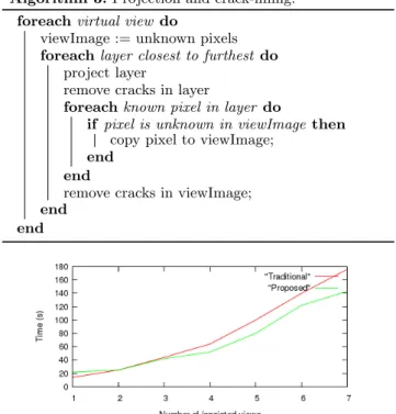
Figure 4: Execution times for traditional and pro-posed pipelines (for same settings).
To evaluate the performance of the proposed approach, two multiview sequences, Ballet and Breakdancers, have been used [6]. They include 8 views (resolution is 1024×768) where the reference views are the views 5 and 3 respectively. The goal is to project these reference views into other cam-era viewpoints and to check if the visual quality between synthesized views is similar. We compare results with two state-of-the-art methods, Daribo [2] and Gautier [3]. As these two methods are based on depth maps, the used depth maps are the projected interpolated ones, as in the pro-posed approach. Figure 5 illustrates a comparison where the reference view is projected into 4 different viewpoints (we call Vi→j, the projection of view i into j). The
qual-ity between synthesized views varies a lot for Daribo and Gautier’s methods, whereas with the proposed approach, the quality is exactly the same ensuring a seamless tran-sition between synthesized views. In other words, when a user wants to move his viewpoint, the quality level stays perfectly consistent. Also note that on Ballet, only the pro-posed approach correctly fills the hole between the man’s arm and chest and correctly differentiates the woman from the wall. Figure 4 gives the running time of the proposed approach and a traditional one [3] in function of the number of synthesized views. When this number increases, the pro-posed approach clearly outperforms method [3]. Figure 6 illustrates the results of the proposed approach on the se-quence BreakDancers. The quality is, again, the same on the different projected views. Note that a quantitative as-sessment is not provided due to both the ill-posed nature of the inpainting approach and the lack of space. More results on http://people.irisa.fr/Olivier.Le_Meur/.
4.
CONCLUSION
We present a new pipeline to synthesize virtual views. In order to ensure inter-view consistency (in terms of quality),
(a) V5→3 (b) V5→4 (c) Reference view V5 (d) V5→6 (e) V5→7
(f) V5→3[2] (g) V5→4[2] (h) Reference view V5 (i) V5→6[2] (j) V5→7[2]
(k) V5→3[3] (l) V5→4[3] (m) Reference view V5 (n) V5→6[3] (o) V5→7[3]
(p) Proposed V5→3 (q) Proposed V5→4 (r) Reference view V5 (s) Proposed V5→6 (t) Proposed V5→7
Figure 5: Virtual view synthesis on the sequence Ballet. (a) to (e): the view V5 is projected into 4 viewpoints.
Disoccluded areas are in red. (f ) to (j): inpainting results of [2]; (k) to (o): inpainting results of [3]; (p) to (t): proposed approach. Note the quality of our results is superior and the same whatever the projection.
(a) Proposed V3→1 (b) Proposed V3→2 (c) Reference view V3 (d) Proposed V3→4 (e) Proposed V3→5
Figure 6: Virtual view synthesis on the sequence BreakDancers.
we propose to inpaint the disoccluded areas before projec-tion. Results show the effectiveness of this approach both in terms of running time and overall quality. A future study would be to consider more than one reference view. The temporal dimension is also an interesting avenue.
5.
REFERENCES
[1] A. Criminisi, P. P´erez, and K. Toyama. Region filling and object removal by exemplar-based image
inpainting. IEEE trans. on Image Processing, 13:1200–1212, 2004.
[2] I. Daribo and B. Pesquet-Popescu. Depth-aided image inpainting for novel view synthesis. In Multimedia Signal Processing (MMSP), pages 167–170, 2010.
[3] J. Gautier, O. Le Meur, and C. Guillemot. Depth-based image completion for view synthesis. In 3DTV
Conference, 2011.
[4] L. Ma, L. Do, and P. de With. Depth-guided inpainting algorithm for free-viewpoint video. In ICIP, pages 1721–1724, 2012.
[5] W. Sun, C. A. Oscar, L. Xu, Y. Li, W. Hu, and Z. Yu. Extended criminisi’s algorithm by modifying the priority function and the patch matching criteria. In ACM Multimedia, pages 733–736, 2012.
[6] C. Zitnick, S. Kang, M. Uyttendaele, S. Winder, and R. Szeliski. High-quality video view interpolation using a layered representation. In ACM SIGGRAPH, pages 600–608, 2004.