is an open access repository that collects the work of Arts et Métiers Institute of Technology researchers and makes it freely available over the web where possible.
This is an author-deposited version published in: https://sam.ensam.eu Handle ID: .http://hdl.handle.net/10985/15558
To cite this version :
Dominique SCARAVETTI, JeanPierre NADEAU, Jérôme PAILHES, Patrick SEBASTIAN -Structuring of embodiment design problem based on the product lifecycle - International Journal of Product Development - Vol. 2, p.47-70 - 2005
Any correspondence concerning this service should be sent to the repository Administrator : [email protected]
the product lifecycle
Dominique Scaravetti*, Jean-Pierre Nadeau,
Jérôme Pailhès and Patrick Sebastian
Trefle – Ensam, Esplanade des Arts et Métiers, Talence cedex 33405, France
Fax: +33 5 56 84 54 36 E-mail: [email protected] E-mail: [email protected] E-mail: [email protected] E-mail: [email protected] *Corresponding author
Abstract: Early stages of the design process are often based on designers’
experience; assumptions and irreversible decisions restricting the solution space are taken. It is difficult to take into account simultaneously every requirement imposed by the different phases of the product life-cycle. In this paper, a method is proposed to perform the analysis of the embodiment design problem. It facilitates the search of the indispensable elements, suitable for structuring the preliminary design phase. Our approach is performed for the relevant life-cycle situations of the product. A four level analysis (need, functions, organic structure and physical behaviours) is proposed. The set of structuring elements allow the design problem definition as a Constraint Satisfaction Problem (CSP).
Keywords: embodiment design; structuring elements; design problem analysis;
decision support system; layout; product life-cycle requirements; CSP.
Reference to this paper should be made as follows: Scaravetti, D.,
Nadeau, J-P., Pailhès, J. and Sebastian, P. (2005) ‘Structuring of embodiment design problem based on the product lifecycle’, Int. J. Product Development, Vol. 2, Nos. 1/2, pp.47–70.
Biographical notes: Dominique Scaravetti is a Teacher at the engineering
school ENSAM since 1997.He holds PhD thesis (ENSAM) in 2004.
Jean-Pierre Nadeau is a Professor at the engineering school ENSAM since 2000. He has been working as a Mechanical engineer from the ENSAM since 1980.
Jérôme Pailhes is a Lecturer at the engineering school ENSAM since 2001. He received his PhD in mechanics in 1999. He has been working as a Mechanical engineer from the ENS-Cachan since 1992.
Patrick Sebastian is a Senior Lecturer at the engineering school ENSAM since 1993. He holds his PhD in mechanics in 1992. He has been working as a Mechanical engineer from the ENSAM since 1989.
1 Introduction
At the preliminary design stage, the decisions being taken influence up to 70% of the life-cycle cost (Figure 1). Several methods have been proposed to structure the global design process (Pahl and Beitz, 1996; Dieter, 2000; Ullman, 2003; Aoussat, 1990; Cavailles, 1995). On the other hand, there are few suitable tools to guarantee the relevance of the embodiment solutions (Yannou, 2001). At this design process stage, the following dilemma appears to be of major importance: designers should be lowly constrained in order to be creative (Matthews et al., 2002) and have to be constrained so that the decisions being taken verify the requirements of the design problem. Thus, it is necessary to have parsimonious but precise information (Sebastian, 2003) in order to be able to initiate the formalisation of the solutions and, on the other hand, to be able to make valid decisions engaging the durability of the choices.
Figure 1 Evolution of committed costs during design process
Source: Zimmer and Zablit (2001).
The systematic approach (Pahl and Beitz, 1996) is rather widespread; however difficulties can arise in the early stages of the classical process of product design. They are mainly related to the simultaneous integration of the requirements stemming from various life-cycle stages, and to decisions that designers have to take early in the design process (Chakrabarti et al., 1992).
First of all, several relevant concepts are rising from conceptual design. Designers have to perform a first choice among these concepts. In order to limit the duration of the design process and to decrease risks, they tend to focus very early towards a solution they can handle. Thus, interesting alternatives might be eliminated, because they are unknown, unused, unusual or non-evaluated.
Then, starting from a chosen concept, embodiment design aims to define rough arrangements and structural dimensions of the indented product, in accordance with technical, economic and aesthetic considerations (Pahl and Beitz, 1996). Designers have to identify key parameters relevant for this definition. Even if there are few parameters and standard elements for a simple mechanism, there is however a great number of possible combinations. Then, designers must make choices (Hicks and Culley, 2002), based on their own experiences. They operate on a try-corrections mode.
So, design iterations cannot be avoided between the conceptual and the embodiment design phases, before reaching design solutions (Ashby, 2000; Hicks and Culley, 2002). This iterative process appears clearly in many models of the literature (Tate and Nordlund, 1996). Moreover, the embodiment solutions are depending on these initial decisions, which greatly limit the field of design investigations.
Another difficulty in an integrated engineering context is the confrontation, as soon as possible, between the different points of view of the design actors and technical skills (technical data, marketing data, company identity, environmental data, ergonomics, cultural and symbolic aspects). Constraints, specific to the product life-cycle phases, must be also taken into account.
More to the point, at a stage where the knowledge is uncertain, most of existing computer-aided tools are based on models requiring the complete geometrical definition of the product. In order to evaluate a design alternative, the performances of several configurations should be estimated rather than a particular solution performance, which might be, moreover, evaluated too late within the design process.
2 Constraint-based embodiment design problem modelling
A decision support system for the embodiment design phase has been developed to overcome these difficulties, by coupling a numeric CSP (constraint satisfaction problem) solver and a knowledge base (Fischer et al., 2002). An approach has been proposed in order to investigate the performances of these tools within known design processes (Scaravetti et al., 2003). It starts from relevant concepts and leads to feasible embodiment solutions. Figure 2 shows the stages and job-status of embodiment design enhanced by the use of the decision support system for a mechanical device design (Scaravetti et al., 2004):
• this process starts from two relevant working structures
• an analysis phase leads to identify the structuring characteristics of the embodiment design problem
• once the model is written, the CSP solver gives the solutions (a solution is a combination of structuring parameters, which check all the listed constraints) • finally, the embodiment solutions are sorted, using an objective function.
Figure 2 Different job status of the enhanced embodiment design phase
The use of this decision support system supposes the transcription of the design problem as a set of constraints (equality, inequality, logical rule). The CSP solver finds out combinations of variables satisfying all the constraints. This approach avoids the a priori decision-making and also shuns dismissing solutions; indeed causality and sequentiality during calculations are avoided.
Instead of starting with one retained concept, several concepts can be described by a set of specific constraints. The choice between several concepts is performed through the numerical processing of the constraint satisfaction problem.
All the conditions that determine the product characteristics are also translated into constraints: geometry, functional requirements criteria and physical behaviours for the relevant life-cycle stages, standard elements, technical skill rules, manufacturing constraint, cost evaluations. The variables can belong to continuous domains; thus, no variable is a priori fixed and the potentialities related to the concepts are preserved. The variables can also be discrete, enumerated and tabulated (catalogues).
The difficulty inherent in this approach is to correctly formalise the knowledge base (set of constraints) so that this base is coherent, non-redundant and complete. Designers require a method for capturing the information in the form of knowledge (Theodosiou and Sapidis, 2004).
We propose an analysis and structuring methodology of the design problem, in order to facilitate the formulation of constraints by designers: this approach is based on a four level analysis (need, functional, structural, physical) leading to determine the relevant parameters of design (like a designer does using his expertise) and to the identification of structuring characteristics and functions, translated later into constraints.
During the first steps of a design project, it is necessary to reduce the extent of the design problem. Designers do not take into account every requirement of the design problem and only some functions are selected. Their reasoning is based on structuring functions that initiate the design process and leads to the first validated product architecture.
In the same way, necessary and sufficient elements are identified in order to limit the embodiment design problem complexity. These elements are called structuring functions and criteria. On the contrary, the systematic approach (Pahl and Beitz, 1996) looks for the exhaustiveness. The purpose of design methodologies is to guide designers and specify a design process with stages and milestones. We do not propose a new design method, but a method to select these structuring elements useful for the design embodiment phase.
3 A four level approach for the design problem analysis and structuring
The proposed methodology for the identification of structuring elements recovers information in functional performance specifications, physical behaviours analysis and technical skill rules. This methodology is based on classical tools performing need analysis, functional and structural analysis. Functional analysis (AFNOR, 1990–1991) is usually used in an industrial context. The regulation documentation necessary for quality certifications and for the reliability, availability, safety assessments are based on functional analysis. It is also useful for tasks identification in project management. Thus, our approach based on classical tools does not necessitate new competences.
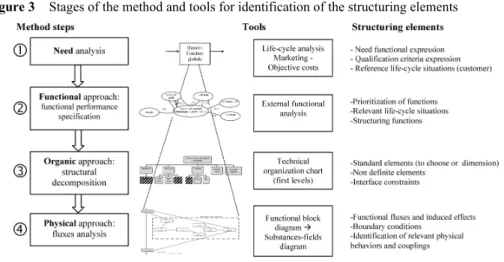
The search for structuring elements is performed by an approach based on a four level problem analysis: need, functional, organic, and physical (Figure 3). For each step, a selection method of structuring elements is proposed.
Figure 3 Stages of the method and tools for identification of the structuring elements
4 Need analysis (step #1)
Need analysis is related to a customer interested in the product. The customer can be: • the end user of the product to be designed; the internal functions do not concern him
and some criteria will not be a part of his qualification criteria.
• a company department, an applicant, a control service, a certifier: he is interested in the criteria related to internal functions and to expected physical behaviours. They will be expressed during the next steps.
4.1 Need expression
A rational and efficient design method starts with an exhaustive formulation of the expressed or implicit user’s need (AFNOR, 1990–1991). At this stage, the customer often formulates its need in marketing and economic terms; the expected results and time limits are also expressed.
The functional analysis translates and integrates the need expression for the end user, the customer and the designer (Prudhomme et al., 2003). However, the need expressed on a functional form, does not prejudge of the architecture of the system to be designed. So, the solutions field is not restricted.
The global function is always structuring, but may not be the most structuring one.
4.2 Product life-cycle analysis
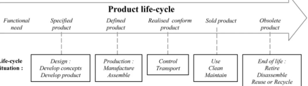
Figure 4 enumerates the life-cycle situations related to the stages of the product life-cycle.
Figure 4 Product life-cycle and the corresponding life-cycle situations
The functional performance specifications expressed by the customer defines expected features of the product. In most cases, it does not systematically mention the life-cycle situations of the product. In that case, it is necessary to determine these situations from the expressed functions. Then, they are organised into a hierarchy from the hierarchical organisation of the functions.
These reference life-cycle situations for the customer, initially expressed or not, will be a part of structuring situations.
New life-cycle situations emerge due to the evolution of the political, economic, industrial contexts, like end of life and recycling for example. These evolutions make prematurely obsolete the products, which did not integrate during their design the constraints connected to these life-cycle situations. These new requirements become inescapable and are imposed for example by standards.
4.3 Qualification criteria for customer
The customer has to express the relevance criteria of the design. These criteria will qualify the proposed design.
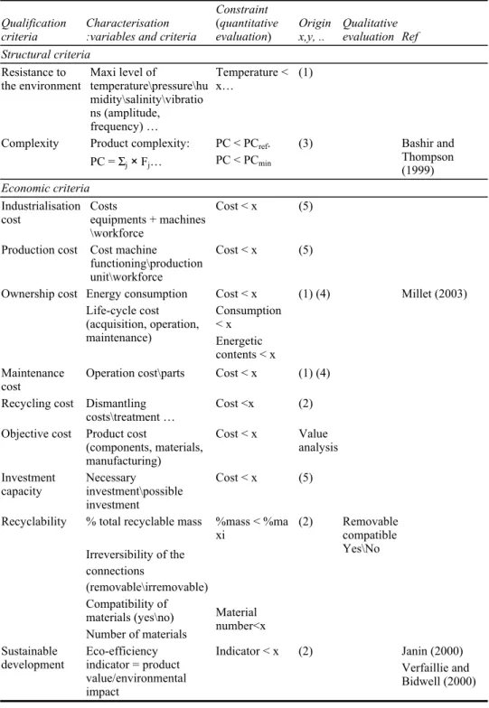
Table 1 enumerates qualification criteria by categories. It indicates the used variables and criteria, as well as the way of writing the constraints.
• The technological functional criteria concern the performances expected by customer and safety requirements. The structural criteria concern the constitution of the product, its resistance to the environment (atmosphere, vibrations, corrosion), its complexity. The product complexity (PC) can be defined as PC = Σj × Fj: j is the level of the functional decomposition and Fj is the number of functions at this level (Bashir and Thompson, 1999). The used functional description is coherent with the technical organisation chart used in the step #3 (see Figure 5): these functions correspond to the functions of every functional block. PC will be calculated later. A limit value can be fixed thanks to a repository and previous projects experience. • The various costs are enumerated in the economic criteria.
• The indicators of environmental impact and of sustainable development are also integrated in the qualification criteria. Several specialised indicators exist. More globally, the eco-efficiency indicator (Janin, 2000; Verfaillie and Bidwell, 2000) compares the economic performance and the environmental performance. It is a relative measurement of the environmental impact. Such indicators can be:
Mass of sold product or net sales per • Energy consumption
• Material consumption • Greenhouse gas emissions
• The qualification criteria relevant for the company and marketing concerns development times, design risks and product perception.
The project duration can be estimated from the product complexity PC (Bashir and Thompson, 1999):
Time (hours) = A × PC D0.85
• ‘A’ is a constant depending on the company size and on the information circulation. It can vary from 30 for a small firm with a good communication, up to 150 for a big company with an average communication (Ullman, 2003).
• ‘D’ is related to project difficulty (1: little difficult, using known technologies; 2: difficult, few new technologies; 3: very difficult).
Larson and Kusiak (1996) and, Sarbacker and Ishii (1997) give indications onto the design risks and their consequences, from the designer point of view; the consequences are always related to the costs and project duration. The index of risk priority (IRP) allows to quantify the risks connected to a system or to a component (Landy, 2002). The risk is defined as a magnitude with two dimensions (characterising one dreaded event): The probability of occurrence and the gravity of the consequences (defined in terms of loss of performance or financial loss) (Grenouilleau et al., 1999).
Table 1 Qualification criteria for customer and characterisation
Qualification
criteria: Characterisation: variables and criteria
Constraint
(quantitative
evaluation) Origin x,y, .. Qualitative evaluation Ref Technological criteria Functional criteria Parameter ∈ [x,y] Parameter∈ {x, y, z} Expected
performances Efficiency\power\physical parameters (force, speed, temperature, pressure …)
Productivity (number of
actions per time unit) Parameter > x (1)
Parameter ∈ [x, y] Regulation Criteria based on
standards
Parameter < x (2)
Minimal life
expectancy MTTF: mean time to (first) failure MTTF > x (1) Ligeron and Lyonnet (1992) Reliability MTBF: mean time
between failures MTBF > x (1) Ligeron and Lyonnet (1992) Availability Indicator of operational
availability:
Dop = MTBF/MTBF +
MTTR
1 > Dop > x (1) Monchy (2000)
MTTR: mean time to repair rate of standard components
MTTR > x (1) Ligeron and Lyonnet (1992) Maintainability
Ease of cleaning Yes/no FMECA criteria:
Criticality = severity level×proba.
occurrence× proba. not detection Criticality < x (3) Landy (2002) Garin (1994) Security Certification requirements Criterion < x (2)
Robustness S/N (signal/noise) S/N maxi (3) Taguchi (2003) Energetic (operation life) (1) Autonomy Do not necessitate human intervention Autonomy > x Yes\no Structural criteria
Mass Total mass, maximum
(or minimum) Mass < x (1) Minimum dimensions
(or maximum) Dimension > x (1) (2) Encumbrance Volume coefficient of the packaging: VCP = parallelopiped packaging volume/contents volume 1 < VPC < x (1) (2) CEN, European Committee for Standardisation (2000)
Table 1 Qualification criteria for customer and characterisation (continued)
Qualification
criteria Characterisation :variables and criteria
Constraint
(quantitative
evaluation) Origin x,y, .. Qualitative evaluation Ref Structural criteria
Resistance to
the environment Maxi level of temperature\pressure\hu midity\salinity\vibratio ns (amplitude, frequency) … Temperature < x… (1) PC < PCref.
Complexity Product complexity:
PC = Σj × Fj… PC < PCmin (3) Bashir and Thompson (1999) Economic criteria Industrialisation
cost Costs equipments + machines \workforce
Cost < x (5) Production cost Cost machine
functioning\production unit\workforce
Cost < x (5)
Ownership cost Energy consumption Life-cycle cost (acquisition, operation, maintenance) Cost < x Consumption < x Energetic contents < x (1) (4) Millet (2003) Maintenance
cost Operation cost\parts Cost < x (1) (4) Recycling cost Dismantling
costs\treatment … Cost <x (2) Objective cost Product cost
(components, materials, manufacturing)
Cost < x Value analysis Investment
capacity Necessary investment\possible investment
Cost < x (5)
% total recyclable mass %mass < %ma xi Irreversibility of the connections (removable\irremovable) Compatibility of materials (yes\no) Recyclability Number of materials Material number<x (2) Removable compatible Yes\No Sustainable
development Eco-efficiency indicator = product value/environmental impact
Indicator < x (2) Janin (2000) Verfaillie and Bidwell (2000)
Table 1 Qualification criteria for customer and characterisation (continued)
Qualification
criteria Characterisation: variables and criteria
Constraint
(quantitative
evaluation) Origin x,y, .. Qualitative evaluation Ref Economic criteria
Power consumption Consumption
< x (1) (4) Water and material
consumption Resources impact indicator Consumption < x RII < x (2) Brent and Visser (2004) Environmental
impact (in the various life-cycle phases : manufacturing, distribution, use, end of life …)
Emissions of gas and pollutants, waste: impact indicator ‘greenhouse effect’: kg of CO2 equivalents emitted impact indicator ‘destruction ozone layer’: kg of CFC11 equivalents emitted Emission < x (2) Millet (2003)
Heat generation: heat
flux Flux < x (2) Humidity generation:
flux of material Flux < x (2)
Qualification criteria for company, marketing
Time (h) = A×PC×D0.85 Duration < x
Project duration % new elements (cf technical organisation chart) % new elements < x (5) Bashir and Thompson (1999) IRP < x Risks: design,
costs, time IRP = gravity×occurrence×vali dation
Possible overruns (costs, time limits)
Overrun < x
(5) Landy (2002)
Necessary
time\qualification Time < x Qualification yes\no Startup
Temperature setting … Time < x
(1) (4)
Level of generated noise Noise level < x (2)
Generation of smell Yes\no Environmental
impact
(nuisances) Visual nuisance Yes\no User
perception Associated variables Variable < x Dore et al. (2003) Legend: Origin of the constraint limit: (1) Functional performance specifications;
(2) Standards and regulations; (3) R&D choice; (4) Marketing and (5) Financial and temporal management of project.
4.4 Relevance indicators
From the relevant concepts, several feasible architectures can be proposed. The relevance indicators give elements to designers to make choices and take decisions.
The adaptable or negotiable or quantifiable qualification criteria (for customer) are then translated into relevance indicators.
Relevance indicators are structuring elements, integrated within the model and calculated. They are suitable to calculate performance indicators (see Section 5.4) and they highlight closeness or distance compared to a reference. They are integrated into objective function(s), useful to sort the embodiment solutions.
5 Functional approach (Step #2)
When external functional analysis is realised for all life-cycle situations, functions and external environments are exhaustively enumerated. We wish to retain the relevant life-cycle situations, organise the functions into a hierarchy and extract those, which are structuring for the problem of preliminary design.
5.1 Choosing relevant life-cycle situations
First of all, the life-cycle situations deducted from the customer’s functional specifications are relevant. They are explicitly expressed or deducted from the satisfaction of the global function or from the functional specifications.
After the external functional analysis, risky life-cycle situations are selected. They concern safety (reliability, maintainability, availability). The more important ones are situations badly mastered and identified thanks to experience feedbacks. Life-cycle situations where product or environment can be modified must be selected. For example: ‘prolonged stop’, ‘functioning in aggressive or polluting environment’ or any situations susceptible to modify the state of the product. The situation ‘maintenance’ is necessary to ensure the good functioning of the product.
‘Design’ and ‘manufacturing’ also retained life-cycle situations, because designers take into account constraints related to manufacturing possibilities (state of the art, technical skills rules).
All these relevant life-cycle situations influence steps #2 and #4 of the structuring and analysis of the design problem. Indeed, these two steps are realised only for these situations.
5.2 Structuring functions
Among the functions stemming from functional analysis, the structuring ones are enumerated into Table 2. The constraints can be expressed in an explicit way when a particular industry is targeted. An example concerning fluids cooling is developed in Bouchama et al. (2003).
Table 2 Different types of structuring functions
Types of structuring functions
Function related to qualification criteria for customer Function with no flexibility
Risky function Already known problems, negative feedbacks Function never realised
Precision or an exactness imposed by the customer Energy management
System behaviour or performances
Standard or regulation to respect: technical or industrial normative documents related to person or material protection.
Imperative constraint function
Interchangeability
Prohibition or imposition of the principle solution: industrial context, usable technologies
qualified concept (Aeronautics; chemical and pharmaceutical industries)
industrial property Known risk
Environmental criteria (Janin, 2000):
legal requirements, standards : impact on environment (release, pollution, waste, noise, consumption of resources, recyclability), re-use, reprocessing, stocking
demountability, with the aim of the materials separation (materials, connections)
Environmental costs: equipments, backfitting, materials (type and number of different materials), assemblies, resumption of packagings
Material:
imposition: food, ageing, resistance (mechanical, chemical, thermal, etc.) Cost Structural constraints Limit time Material: unavailability
prohibition (danger, standards…), in the product or in the process
dependence material/process (if process is imposed) supply, supplier
Manufacturing functions (manufacturability, facility of assembly, treatment of surface, etc.)
Table 2 Different types of structuring functions (continued)
Types of structuring functions
Company know-how rules Technical repository
Design rules (guidelines)
Manufacturing rules specific to the company know-how General rules
Embodiment design rules (Pahl and Beitz, 1996) Manufacturing rules
Technical skill rules related to the application of codes Way to design, banned solutions
Manufacturing modes Technical skill rules
Controls, maintenance
For the structuring functions, assessment criteria and variables are expressed. An assessment criterion allows to appreciate the way a function is filled or a constraint is satisfied (AFNOR, 1990–1991). The level and the flexibility of a criterion can be translated on a constraint form.
A redundancy can appear between these assessment criteria and qualification criteria for customers. The redundancy is useful to guarantee the exhaustiveness of the identification of the structuring elements.
• Functions with no flexibility are identified thanks to functional performance
specifications when assessment criteria are enumerated (level, flexibility, limit …). Functions with low or nil level flexibility are retained as structuring functions. • Risky functions (on the technical level) are identified thanks to already known
problems, negative feedbacks, etc. For that purpose, it is necessary to capitalise knowledge and to know how to reuse it. According to Ullman (2003), when knowledge is weak they are critical functions. A risky function can result from a precision or an exactness imposed by the customer.
A function that was never realised might be risky. Risk analysis takes into account the novelty, complexity, arisen events and gravity of the consequences related to the product design (Leroy and Signoret, 1992).
A functional risk might occur when the energy is badly managed, entailing a dysfunction (Desroches, 1999).
• Imperative constraint functions are imposed by the external environments
(technology, market, situation and choices of the company, etc.). On one hand, there are constraint functions (AFNOR, 1990–1991) concerning system behaviour or performances (legal regulations, imposed materials or solutions, etc.). On the other hand, some structural constraints do not concern directly the realisation of a function (time limits, supplying, etc.).
• Technical skill rules are identified through functional analysis, for the life-cycle
situations ‘design’ and/or ‘manufacturing’ and/or control and/or maintenance. For example, these rules intervene as soon as that the company has to manufacture ‘with the potential of the company’:
• Know-how rules of the company. Design rules, calculus rules, manufacturing rules,
cost or duration estimation rules, etc.
• A manufacturer has technical reports, capitalising the know-how and defining criteria to be respected. For a car manufacturer for example: ground
clearance, protection of the electric wires, seat command (ergonomics), design recommendations for recycling, etc.
• Guidelines for the environmental integration are used by some manufacturers (Janin, 2000). They enumerate the banned or advised materials, instructions of conception in order to facilitate their dismantling, their recycling, etc. • Manufacturing rules connected to the company know-how, induce design
constraints (curvature radius of pipes, minimum crankcases thicknesses, etc.). • Global design rules. Embodiment design rules (Pahl and Beitz, 1996) are concerned
with form choices appropriated to manufacturing processes or facilitating the assembly.
• Technical skill rules indicate the type of tool or material to be used, in order to obtain for example, a surface specification or a tolerance.
• Technical skill rules related to the application of professional codes. These dimensioning codes are related to a specific product or industry sector: CODAP (pressure vessels), EUROCODE, BAEL (civil engineering), PS (seismic), RCCM, FEM, CM66, ASME, NEIGE, VENT, etc.
The codes impose the way to design, the banned solutions, the manufacturing modes, the controls and maintenance to be made. They also impose the calculation rules connected to the materials being used and prescribed manufacturing processes. In some cases, the physical models are supplied. This type of constraint is raised in the stage #4 (physical approach).
These enumerated structuring functions generate constraints (equality, inequality, logical rules), intervals or enumerations among which variables will be chosen.
5.3 Relevance indicators, from the designer’s point of view
Technical rules may impose causality between the variables, that is to say, a procedure or an algorithm to treat the design problem. Designer criteria might not be expressed in the functional performance specifications. These intermediate elements are useful to compare some design alternatives. Designer criteria are relevance indicators:
• Relevant criterion in the realisation of a technical function. The designer may add parameters which are not expressed by the customer, but allow him to qualify a function.
• The functioning risk can be estimated by the distance compared to a reference (standard, rule, experience feedback, test on prototype) with the performance indicator.
5.4 Performance indicator
Once identified the relevance indicators stemming from the qualification criteria for the customer and the designer’s relevance indicators, we compare them with a reference.
A performance indicator highlights relevance indicator’s closeness or distance compared to a reference.
A performance indicator must be minimised.
• Ip = I/I ref, if the performance corresponds to the distance compared to the reference. In that case, it is connected, for instance, with a risk of operation.
• Ip = I ref/I, if the performance corresponds to the closeness compared to the reference. In that case, it is connected, for instance, with an optimisation process. The reference (I ref) can be:
• Fixed. An evaluated element, imposed by the customer, by standards, etc. It is a
fixed reference, intrinsic to the problem and independent from the context. If it can be expressed, it is preferable to use it.
A risk can be evaluated by knowing a reference. For example, the distance of a parameter can be quantified by comparison to a standard.
The degree of change can also be quantified. In certain cases of re-design, minimising changes is needed.
• Relative. The minimal or maximal value of a relevance indicator among a set of
results: For a given configuration and a given context, the solutions can be compared with each other regarding the indicator.
So, the performance indicators allow:
• The comparison regarding a customer reference: it necessitates to overcome the
calculation of the indicator corresponding to this reference.
• The comparison of the solutions between them. If a criterion cannot be defined completely, it is however necessary to identify relevant parameters relative to the criterion.
A comparison between concepts can be (Ullman, 2003):
• absolute: each concept is compared to objectives using criteria
• relative: concepts are compared by using measurements defined by the criteria. 6 Organic approach (Step #3)
The product concept is defined in a first technical organisation chart by assembling functional blocks (Figure 5).
However, only the first levels define the product at the conceptual stage. Beyond the first levels, other choices are realised, during the embodiment design phase.
Figure 5 Technical organisation chart
Table 3 Structuring organic elements
Structuring elements Characterisation
To be chosen
Intrinsic constraints : dimensions interfaces energy supply Constraints related to life-cycle situations:
• constraints of use
• warehousing, transport, etc.
Susceptibility to harmful factors To be dimensioned Standard element Dimensioning rules Non-defined elements Wanted, useful Contact:
geometry, encumbrance, connection, fixationassembly tension, amperage energetic Distant: computational thermal (radiation) Non-wished (harmful)
Contact: energetic (exchanges, losses) Interface constraints
Distant: electromagnetic compatibility (interference) thermal (radiation), etc.
For example, a domestic vacuum cleaner with a disposable bag can be decomposed in three main functional blocs (pipe, fan, bag) and two external environments (air, dust).
The standard elements are to be chosen or dimensioned:
• The standard components to be chosen are components ready-to-use belonging to catalogues. Their choice is made on relevant parameters, relative to the functions they perform.
They impose their intrinsic constraints (dimensional constraints, interface constraints, energy supply, etc.): these variables are identified in the problem, but they can take only standard values. On the other hand, some constraints are associated to various life-cycle situations, not directly connected to the functions they fulfil, and given by the manufacturers (constraints of use, warehousing or transport, etc.). It is also necessary to investigate their sensitivity to harmful factors. • The standard elements to be dimensioned are concepts already mastered by the
company (known functional blocks, where only some parameters are adjusted). Dimensioning rules exist for these typical elements; they arise from the company knowledge, from technical books or from professional dimensioning standards (CODAP, TEMA, etc.).
• Design of non-defined elements cannot be avoided and are thus structuring. They have to be dimensioned.
The design risk is estimated (Landy, 2002) and choices have to be made according to the anticipated risk. The badly known alternatives are dismissed.
• The relations between the system and the external environments are enumerated. The interface constraints express the compatibility between the elements or between one element and its environments. Some interface constraints may be already identified at the previous step.
Various types of interfaces are (Cavailles, 1995):
• functional interface (compatibility of mechanical links, electric or electronic links):
connections, fixation; assembly; tensions, amperages; signals (input, output, form); computer interface (protocols, languages)
• physical interface, compatibility between characteristics of nearby constituents:
electromagnetic, geometrical compatibility (encumbrance, assembly …)
For the interfaces, the connection between two elements must be checked and the conservation laws of fluxes must be satisfied.
7 Physical approach (Step #4)
The model of the design problem has to contain a description of the relevant physical behaviours. In order to enumerate them, the structuring variables and behaviour of the system have to be investigated in an exhaustive way. For that purpose, functional block diagrams (FBD) and substances-fields graph (SFG) are used.
Table 4 Structuring elements related to the physical approach
Structuring element Characterisation
Key elements, in which the main functional flux passes through
Conservation laws of mass
of energy (heat, mechanical or deformation energy, etc.)
of the impulse of electric charge Relevant and dominating
physical behaviour
Boundary conditions Induced relations of coupling pressure losses
models of contact, friction electromagnetic interaction
deformation, fastening, creep clogging etc.
Durability of components Calculation rules imposed by the professional codes
Mechanical functions (rigidity, elasticity, resistance to fatigue, wear, shocks, etc.)
Material criteria
Specific functions: thermal, chemical (resistance to corrosion, etc.), electric, optical, magnetic, acoustic, etc.
The FBD is a representation of the path of the functional fluxes through a system corresponding to a life-cycle situation. These fluxes connect the external environments to the system or the system components together (internal fluxes). The designer has to choose the level of the system representation. Indeed, FBD is suitable to describe the whole system or only a functional block. At a detailed level, its use may be complex. A FBD corresponds to each design solution.
Completing each function induces a flux (Ullman, 2003) and fluxes may be of various nature: energy, material, information, user esteem. The functional flux path corresponding to the functional conditions can be visualised using the FBD. The main functional fluxes pass through structuring elements.
The contact graph lists exhaustively the connections between functional blocks. The distant actions are estimated using a systematic questionnaire. The effects of gravity, mobile parts (effects of inertia or centrifugal), non-material fields (sounds, ultrasounds, optics, electric, radiation, magnetic, etc.) are successively examined.
However, the FBD does not identify the interactions between the transported materials and the induced effects. The FBD solely describes the functional fluxes passing through the components. Moreover, only the useful functional components appear within the FBD, whereas the effects quoted above are not taken into account. The physical behaviours are described more precisely with substances-fields graph (SFG) (Savransky, 2000).
SFG is suitable to integrate the transported materials or present materials into the system, and to take into account the generated fluxes and the effects induced by these fluxes. A systematic list of generated fluxes and induced effects has been proposed (MAL’IN, 2003). TRIZ theory differentiates the useful or insufficient functions and the unwanted effects (harmful effects).
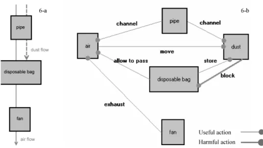
Figure 6 displays the evolution from a given FBD (partial) to a SFG. These graphs concern the functions ‘to suck up and store the dust’ for the domestic vacuum cleaner. We found the functional blocks identified in the previous step (Figure 7).
Figure 6 From FBD (6(a)) to SFG (6(b)), for a vacuum cleaner
Figure 7 Technical organisation chart of a vacuum cleaner
Figure 6(a) presents the different fluxes of system: the fan generates an air-flow through the pipe and the porous bag. This air-flow transports the dust to the bag. The FBD (Figure 6(a)) provides exclusively information in term of material fluxes (air and dust). More precise elements would necessitate coming down at the lower systemic level for the disposable bag.
SFG (Figure 6(b)) displays the ‘substances’ of the system (components and elements transported by the fluxes) and the actions between the substances called ‘fields’. The actions are useful (air moves the dust) or harmful (dust clogs the disposable bag holes, the bag clogging perturb the air flux).
These actions are characterised by physical behaviours. For example, the generated air flux is related to a pressure gradient (state-variable of the air) allowing the transport of the dust.
These physical behaviours are structuring for the design problem. Tables (like Table 1), give an exhaustive vision of fluxes generated by the gradients of state-variables and their induced effects. These tables are available during the definition of the graphs with the software tool MAL’IN (2003) (online help).
These graphs have to be interpreted to determine the constraints of the design problem. The functional fluxes are achieved through physical phenomena. At this stage, designers have to choose, among the set of identified phenomena, the physical behaviours that can be neglected. These choices are subjective and appeal to the designers’ experience.
The relevant and dominating physical behaviours are highlighted by this approach. Each physical flow is related to one or several constraints:
• Fields are translated by continuity conditions between the substances. The conditions of the flux passage are identified through the physical phenomena corresponding to interaction between substances and determine the boundary conditions.
• Fluxes are interpreted by behaviour laws or/and physical conservation laws. Fluxes can convey material or energy. Balances must be written (mass conservation, energy conservation, etc.).
Some fluxes result from gradients of state-variables such as temperature or pressure. These fluxes may induce non-wished effects such as pressure losses, dilation, creep, deformation, clogging, etc. This phenomena identification process gives the opportunity to express the durability of components. Complementary material criteria related to mechanical functions (rigidity, elasticity, etc.) or to specific functions (thermal, chemical …) may result from this process.
System behaviours may be also determined using professional codes (step #2). In these codes, the calculation rules and physical models may be supplied to the designer: the physical behaviours are translated in a parsimonious way in agreement with the dimensioning needs of the embodiment design.
The physical phenomena identified below lead to the definition of relevant variables. In the vacuum cleaner example, the harmful action ‘bag clogging’ is related to a physical behaviour described using the relevant variables: bag porosity, bag volume.
8 Recapitulation of structuring elements of the product life-cycle
The constraints specific to certain phases of the product life-cycle initiate the identification approach of structuring elements during the preliminary design:
• Structuring life-cycle situations of the product are identified (step #1). During steps #2 and #4, tools are deployed only for these situations of the life-cycle.
• Specific constraints corresponding to certain life-cycle situations are displayed through the following structuring elements:
• design: qualification criteria for company, technical skill rules, imperative
constraint functions
• manufacturing: technical skill rules, economical criteria
• supply of components and possible materials: imperative constraint functions
• marketing: economical criteria, marketing criteria
• use (situation often the most described by the customer and the functional specifications): performance criteria, structural and economical criteria,
imperative constraint functions, physical behaviours
• control, maintenance: economical criteria, technical skill rules
• beneficiation, recycling: economical and marketing criteria, imperative
constraint functions.
• Constraints specific to life-cycle situations of the standard elements are identified (transport, use, etc.). They are supplied by the manufacturers.
All the items listed above take into account the constraints related to the life-cycle of the product in the definition of the embodiment design problem.
The set of solutions satisfying all these constraints defines the field of solutions.
9 Conclusion
Based on functional analysis, a method has been proposed to help designers to define and enumerate the structuring elements in the early phases of the design process. This method is involved in the preliminary analysis of a design problem and leads to a set of structuring functions, criteria and components. These elements are those that are necessary and sufficient for the preliminary design phase.
After performing the life-cycle analysis, an analysis divided into four stages has to be carried out:
• need analysis • functional analysis • organic analysis • physics analysis.
Several tables defining an exhaustive enumeration of structuring elements have been proposed. The quality of the functional and physical analysis determines the performances of the results obtained by this method.
An example of application for a mechanical device (see Scaravetti et al., 2004) illustrates this method and has been involved in the aid to choice (choice between several concepts of solution and choice of components) and in the search of feasible embodiments. An improvement of the design process duration was observed thanks to the reduction of the iterations. The choices carried out also facilitate the detail design. Finally, the choice performed within the field of embodiment solutions based on an objective function, maximises the performances expected by the customer (physical behaviour, cost).
These works have been involved in a global project aiming to develop decision-making tools for preliminary design:
• the software MAL’IN (Methods for Innovation Aid) is being developed in our laboratory
• the software CONSTRAINT EXPLORER within the framework of the RNTL project CO2 (national network of software technologies: Design and Constraint
Programming).
This project CO2 gathers Dassault Aviation, CRIL Technology, TREFLE and LIPSI
laboratories (interested in design) and artificial intelligence laboratories: LINA and LIP6.
References
AFNOR – Association Française de NORmalisation (1990–1991) NF X50-150 & 151 Analyse de la
Valeur, Analyse Fonctionnelle: Vocabulaire – NF X50-152 Analyse de la Valeur, Caractéristiques Fondamentales, AFNOR editions, Paris.
Altshuller, G. (1984) Creativity as an Exact Science, Gordon and Breach Science Publishing House, New York.
Aoussat, A. (1990) La Pertinence en Innovation: Nécessité d'un Approche Plurielle, PhD thesis, Ensam, Paris.
Ashby, M.F. (2000) Choix des Matériaux en Conception Mécanique, translated from English, Dunod (Ed.), Paris.
Bashir, H. and Thompson, V. (1999) ‘Estimating design complexity’, Journal of Engineering
Design, Vol. 10, No. 3, pp.247–257.
Bouchama, A., Sebastian, P. and Nadeau, J.P. (2003) ‘Flash evaporation, modelling and constraint formulation’, Trans. I. Chem E., Part A., Vol. 81, pp.1250–1258.
Brent, A.C. and Visser, J.K. (2004) ‘An environmental performance resource impact indicator for life cycle management in the manufacturing industry’, Journal of Cleaner Production, Vol. 13, No. 6, pp.557–565.
Cavailles, J. (1995) Méthodes de Management de Programme, 2nd ed., DGA-Teknea.
CEN, European Committee for Standardization (2000) European Standards: Packaging
Requirements EN13427, 13428, CEN, http://www.cenorm.be.
Chakrabarti, A., Bccgh, T.P. and Holden, T. (1992) ‘Towards a decision-support framework for the embodiment phase of mechanical design’, Artificial Intelligence in Engineering, No. 7. Desroches, A. (1999) ‘Aspects conceptuels des risques’, Proceedings of PRIMECA Le Risque, la
Sûreté de Fonctionnement, la Fiabilité en Phase de Conception des Produits et des Systèmes,
Paris.
Dieter, G.E. (2000) Engineering Design – A Materials and Processing Approach, 3rd ed., McGraw-Hill International Editions, New York.
Dore, R., Fischer, X., Nadeau, J.P. and Pailhes, J. (2003) ‘Méthodologie avancée pour la conception conforme utilisateur’, Proceedings of AIP-PRIMECA, La Plagne.
Fischer, X., Nadeau, J.P., Sebastian, P. and Joyot, P. (2002) ‘Qualitative constraints in integrated design’, in Chedmail, P. et al. (Ed.): Integrated Design and Manufacturing in Mechanical
Engineering, Kluwer Academic Publisher, pp.35–42.
Garin, H. (1994) AMDEC/MADE/AEEL – L’Essentiel de la Méthode, AFNOR editions, Paris. Grenouilleau, J.C., Desroches, A., Dejax, P. and Peres, F. (1999) ‘Analyse des risques
opérationnels liés à la gestion des éléments de rechange d'un système spatial complexe en phase de conception’, Proceedings of PRIMECA Le Risque, la Sûreté de Fonctionnement, la
Hicks, B.J. and Culley, S.J. (2002) ‘An integrated modelling environment for the embodiment of mechanical systems’, Computer-Aided Design, Vol. 34, No. 6, pp.435–451.
Janin, M. (2000) Démarche D'éco-Conception en Entreprise – Un Enjeu: Construire la Cohérence
Entre Outils et Processus, PhD thesis, Ensam, Chambery.
Landy, G. (2002) AMDEC Guide Pratique, AFNOR editions, Paris.
Larson, N. and Kusiak, A. (1996) ‘Managing design processes: a risk assessment approach’, IEEE
Transactions on Systems, Man and Cybernetics, Vol. 26, No. 6, pp.749–759.
Leroy, A. and Signoret, J.P. (1992) Le Risque Technologique, Presses Universitaires de France, Paris.
Ligeron, J.C. and Lyonnet, P. (1992) Fiabilité en Exploitation, Lavoisier editions, Paris.
MAL’IN (2003) Méthodes d'Aide à L'INnovation (Methods for Innovation Aid), http://www. lept-ensam.u-bordeaux.fr/malin, Trefle-Ensam, Bordeaux.
Matthews, P.C., Blessing, L.T.M. and Wallace, K.M. (2002) ‘The introduction of a design heuristics extraction method’, Advanced Engineering Informatics, No.16, pp.3–19.
Millet, D. (2003) Intégration de L'environnement en Conception – L'entreprise et le
Développement Durable, Lavoisier, Hermes Sciences.
Monchy, F. (2000) Maintenance, Méthodes et organisation, Dunod (Ed.), Paris.
Pahl, G. and Beitz, W. (1996) Engineering Design: A Systematic Approach, 2nd ed., Springer-Verlag, Londres.
Prudhomme, G., Zwolinski, P. and Brissaud, D. (2003) ‘Integrating into the design process the needs of those involved in the product life-cycle’, Journal of Engineering Design, Vol. 14, No. 3, pp.333–353.
Sarbacker, S.D. and Ishii, K. (1997) ‘A framework for evaluating risk in innovative product development’, Proceedings of the ASME Design Engineering Technical Conference, Sacramento.
Savransky, S.D. (2000) Engineering of Creativity: Introduction to TRIZ Methodology of Inventive
Problem Solving, CRC Press, New York.
Scaravetti, D., Nadeau, J.P. and Sebastian, P. (2003) ‘Structuring functions and constraints formulation; for an enhanced embodiment design’, Proceedings of International CIRP Design
Seminar, Grenoble.
Scaravetti, D., Nadeau, J.P., Sebastian, P. and Pailhes, J. (2004) ‘Aided decision-making for an embodiment design problem’, Proceedings of International Conference on Integrated Design
and Manufacturing in Mechanical Engineering, Bath.
Sebastian, P. (2003) Approximation et Intégration de Modèles Pour L’aide à la Décision en Génie
des Procédés, Mémoire d’Habilitation à Diriger des Recherches, Université Bordeaux 1.
Taguchi, G.S. (2003) Key Concepts for Robust Engineering Using Taguchi Methods, American Supplier Institute, Séminaire sur les méthodes Taguchi, Ensam, Paris.
Tate, D. and Nordlund, M. (1996) ‘A design process roadmap as a general tool for structuring and supporting design activities’, Proceedings of the 2nd World Conference on Integrated Design
and Process Technology, Austin.
Theodosiou, G. and Sapidis, N.S. (2004) ‘Information models of layout constraints for product life-cycle management: a solid-modelling approach’, Computer-Aided Design, Vol. 36, No. 6, pp.549–564.
Verfaillie, H.A. and Bidwell, R. (2000) ‘Measuring eco-efficiency – a guide to reporting company performance’, World Business Council for Sustainable Development, Switzerland, http://www.gdrc.org/sustbiz/wbcsd.html.
Yannou, B. (2001) Préconception de Produits, Mémoire d’Habilitation à Diriger des Recherches, INPG.
Zimmer, L. and Zablit, P. (2001) ‘Global aircraft predesign based on constraint propagation and interval analysis’, Proceedings of Ceas Conference on Multidisciplinary Aircraft Design and