is an open access repository that collects the work of Arts et Métiers Institute of
Technology researchers and makes it freely available over the web where possible.
This is an author-deposited version published in: https://sam.ensam.eu
Handle ID: .http://hdl.handle.net/10985/10309
To cite this version :
Javier Rios QUESADA, Jean-Frederic CHARPENTIER - Finite Difference Study of
Unconventional Structures of Permanent-Magnet Linear Machines for Electromagnetic Aircraft Launch System - IEEE TRANSACTIONS ON MAGNETICS - Vol. 41, n°1, p.478-482 - 2005
Any correspondence concerning this service should be sent to the repository Administrator : archiveouverte@ensam.eu
Finite Difference Study of Unconventional Structures
of Permanent-Magnet Linear Machines for
Electromagnetic Aircraft Launch System
Javier Rios Quesada and Jean-Frederic Charpentier
Abstract—This paper deals with the design of an electromag-netic aircraft launch system (EMALS). The system studied is based on a linear permanent-magnet (PM) machine. For the same thermal, geometric, and feeding specifications, original configu-rations of linear machines have been studied and compared to more classical ones in terms of performance. The work shows that originals structures which use Halbach array configuration in as-sociation with unconventional winding strategy can produce very interesting solutions with which to build an EMALS synchronous PM machine.
Index Terms—EMALS, Halbach, linear machine, permanent magnet.
I. INTRODUCTION
T
HE aircraft launch systems currently in use on aircraft carriers are based on steam technology. This technology presents significant drawbacks. Mainly, a steam catapult works as an open-loop control system, has large transients of force, and unpredictable variations of thrust. The occupied volume in the carrier is very high. Furthermore, the steam technology has a very low efficiency and needs a high maintenance level [1], [2].Military all electric ship (AES) designs result in the use of
electricity to distribute, control, and deliver the energy in all the on-board power applications (propulsion, weapons, etc.). With this trend, an interesting solution to accelerate an aircraft to the fly away speed from an aircraft carrier is an electromagnetic
aircraft launch system (EMALS). This system includes energy
storage, power electronics drive, and a linear launch electrical motor.
The current research on EMALS is based exclusively on syn-chronous permanent-magnet solutions for the linear machine [1]–[4]. The machine can be driven by a voltage pulse width modulation (PWM) inverter which allows the current to be con-trolled in the machine windings. The launcher shuttle is built with high-energy rare-earth permanent magnets and can have two different basic structures: a blade shuttle or an inverted shuttle (Figs. 1 and 2). In the inverted structure, the shuttle is overlapping a central stator with a double winding. In the blade structure, the shuttle is put between two lateral stators.
Recently, Patterson et al. proposed a fully integrated solu-tion including a permanent-magnet (PM) linear machine with
Manuscript received December 19, 2003.
The authors are with the French Naval Academy Research Institute, BP 600 29240 Brest Armées, France (e-mail: charpentier@ecole-navale.fr).
Digital Object Identifier 10.1109/TMAG.2004.838990
Fig. 1. View of an EMALS with blade structure.
Fig. 2. View of an EMALS with invertedU structure.
the power electronics drive and control [3]. In this work, a clas-sical structure of a blade PM linear machine is used in associa-tion with some H bridge PWM inverters. These power electronic drives feed each winding of the PM machine.
This paper dwells on some original PM linear machine struc-tures with the same thermal, mechanical, electrical, cost, and ge-ometrical specifications. Therefore, we consider the same power supply and the same thermal behavior, overall dimensions, and material characteristics as in the Patterson et al. EMALS design. This study allows us to compare the performances of un-conventional machine designs with the Patterson design. These studied designs use unconventional windings and magnetization strategies for blade and for inverted structures.
II. SPECIFICATIONS ANDTECHNICALFEATURES
A. Launching Specifications
If we consider a typical launch of a military aircraft from an aircraft carrier deck, a mass of kg (shuttle aircraft) has to be accelerated from 0 m/s to a final velocity
m/s. The length of the launch track is m. Let be the force of linear motor, its acceleration, and
the launch time. If is considered as constant and as the 0018-9464/$20.00 © 2005 IEEE
only force in the system (the friction force and the thrust of aircraft motors are not significant), the mechanical system can be modeled by
(1) (2) (3) where is a constant acceleration. The numeric application gives
MN m s s
Therefore, the launch energy required to impulse the set (shuttle aircraft) is 125 MJ and the required power is 62.5 MW.
B. Brake Specifications
After the launch, the shuttle must stop completely within 10 m. Therefore, the minimal force, , to electrically brake the shuttle is
(4) where is the shuttle mass and is the braking distance.
If the electrical brake system must have the same electronic drive constraints (same maximal current in the windings) as for the launch, the maximal brake force is constant and equal to the launch thrust of the EMALS. Therefore, for MN the maximal shuttle weight is 2500 kg.
C. External Dimensions Specifications
The external dimensions (length, width, and depth) of the linear machine are fixed and are equal to those chosen by Patterson.
All these specifications are summarized in Table I.
D. Power Electronics Drive Specification
In this paper the same constraints on power electronics and same feeding strategy as in the Patterson design are used. The PM linear machine is used in association with a PWM voltage inverter and a two-phase energized constant 120 current con-trol strategy. This strategy is very near to the basic concon-trol of a classical brushless PM motor with a six-step current switching (Fig. 3).
In the Patterson power electronics design, each phase is sec-tioned along the track. Four independent turns are used in par-allel for each phase section of the two windings. Each of the four turns is fed with an independent IGCT H bridge with a maximum current of 4.5 kA and a voltage dc source of 4 kV. Therefore, the total current per pole and per phase in the ma-chine slots is 18 kA when the corresponding phase section is energized.
TABLE I EMALS SPECIFICATIONS
Fig. 3. EMALS feeding strategy with 120 current control.
E. Performances Characteristics
The main characteristics which define the PM linear machine performances are as follows.
• The launch thrust, which must be greater or equal to 1.25 MN. If a greater thrust is obtained for the same feeding and thermal constraint, that means the power electronics drive system can designed to be less powerful than the Patterson one (lower current) to obtain the re-quired thrust. On the other hand, if the power electronics
system is the same as in the Patterson design, a heavier plane can be launched.
• The value of the inductance per phase and per pole for a single conductor by slot (one turn) must be minimized. This inductance value corresponds to a very important constraint for the current control strategy. If the inductance seen by each H bridge is too great, the maximum current cannot be controlled for the maximum speed at the end of the track. The maximum drivable inductance for each power inverter H bridge for the chosen power electronics drive specifications is about 0.25 mH. For the Patterson machine design (8 H per pole and per phase), it corre-sponds to a maximum 5 m section (around 33 poles) at the end of the track. If the machine has a lower inductance per pole, per phase, and per winding turn, bigger sections of track can be fed and the power electronic drive can be simplified.
III. STUDIEDSTRUCTURES
The aim of this study is to compare conventional and uncon-ventional structures of the PM linear machine to maximize the thrust and minimize the inductance per pole and per phase for one turn.
A. Shuttle Configurations
Five structures of shuttle have been studied in this paper. First, blade shuttle structures are considered. Two kinds of blade structures are studied. The first ones are built with classical magnetization (normal to the air gaps) magnets. The second ones are built with normal and tangential magnets to form a double basic Halbach array. These two kinds of shuttle do not have ferromagnetic parts.
Three inverted shuttles are also studied. Two kinds of magnet dispositions are studied. The first one is the classical one with the magnets oriented normally to the air gap. In this first case, a soft ferromagnetic (iron) core must be used to channel the flux. This solution leads to heavier shuttles than in the blade configuration. This weight can be problematic for the brake operations. The second and third ones use tangential and normal magnets. These magnets form a simple Halbach array. In this Halbach array configuration, the magnetic flux is channeled in the magnet layer. In this configuration an iron core is not necessary. Therefore, these Halbach array shuttles structures are considered with or without iron cores.
These five configurations are shown in Fig. 4.
All the considered configurations correspond to the same magnet layer thickness, magnet magnetization, air gap, and pole pitch as presented in the Patterson work:
• the pole pitch is 150 mm;
• the magnet magnetization is 1.15 T (neodymium iron boron magnets);
• the magnet width is 2 50 mm for the inverted structure and 100 mm for the blade structure.
The Patterson length of the shuttle is 3 m (20 poles).
Fig. 4. Four poles shuttles for different possible structures.
B. Winding Strategies
These five shuttle configurations are associated with three stator winding strategies:
• the first strategy corresponds to the classical solution: a distributed winding with a polar step;
• the second strategy is a juxtaposed winding with a reduced step;
Fig. 5. Studied winding distribution (four poles). TABLE II
LINEARMOTORCOMMONSPECIFICATIONS
Fig. 5 shows these three types of windings for four consecu-tive poles.
All the considered configurations corresponds to the same set of main specifications. These specifications are summarized in Table II.
IV. RESULTS
A. Performance Calculation Method
The performances of the studied machines are calculated using a finite difference two-dimensional (2-D) code with magnetostatic hypothesis, saturation, and motion. We consider a two-pole (distributed and reduced step juxtaposed windings) or a four-pole (polar juxtaposed windings) study domain with periodicity conditions for the inverted and the blade systems. As an example, Fig. 6 shows the obtained vector equipotential map for the normal magnetization with conventional winding case for a blade and an inverted structures. This calculation method allows the evaluation of the performance of the linear machine for one pair of poles of the structure. The global performance is obtained multiplying the obtained results by the number of pole pairs. Within these hypothesis, the edge effects at each end of the structure are not taken into account.
Fig. 6. Example of magnet field distribution in EMALS PM linear machine. The average thrust by shuttle pole pairs is calculated in this way for each of the studied structures for a global current of 18 kA per pole and per phase in each of the two stator windings (same electric loading and current density in the slots). If this thrust is bigger than the reference thrust of 125 kN per pole pair obtained by Patterson (1.25 MN for a ten pole pair shuttle), two solutions can be considered to improve the reference design. If the electronic drive specifications are the same as in the Pat-terson design, the shuttle length (i.e., the shuttle number of pole pairs) can be reduced for the same delivered thrust. That means the weight of the shuttle is also reduced and the final braking is made easier. The price of the shuttle which is mainly related to the magnet volume is also reduced. If the shuttle number of pole pairs is the same than in the reference design, that means the electronic drive can be simplified: the maximal armature cur-rent can be reduced to obtain the required thrust performance. Furthermore, in this last case, if a lower current is needed for the same thrust, the back EMF of each stator phase at the end of the track (maximal speed) is more important than in the reference case. That means it is necessary to adapt the dc voltage source value or the track sectioning to a bigger value of the back EMF, to be able to control the current in each armature winding.
The inductance value for a single conductor per slot for one phase and for one pole pair is also calculated. This value is a very important constraint in terms of control feasibility. If the inductance level is lower than the reference value (8 H), that means the machine armature current can be driven more easily and that bigger end sections of track can be considered. So if this value is lower than the reference one, the power electronics and the control strategy can be simplified.
B. Blade Structures Results
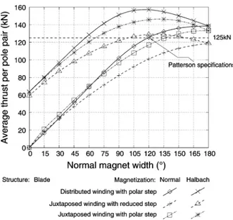
In this part, blade structures with a normal magnetization and with Halbach array basic magnetization are considered (Fig. 4). These structures are associated with the three studied winding configurations (Fig. 5). The results for these six kinds of linear machines are given as functions of the width of the normal magnet in the shuttle pole as shown in Fig. 4 (this magnet width has a maximal value of 180 electrical degrees which corresponds to the pole pitch).
Fig. 7 shows the performances of the structures in terms of thrust obtained for these six blade configurations.
For the three kinds of winding configurations the inductance values by pole pair and by phase are respectively 8, 5, and 12 H for the distributed winding, the juxtaposed windings with re-duced step, and the juxtaposed windings with polar step. These values are quasi-similar for the blade and inverted structures. So it can be seen that a juxtaposed winding with reduced step
Fig. 7. Blade structures with normal magnetization: Average thrust versus magnet electrical angular width.
Fig. 8. Magnet field distribution in two kinds of invertedU Halbach array linear PM machine.
can be very advantageous in terms of Joule losses (smaller end windings) and inductance value. So the structures with juxta-posed reduced step windings appears to be interesting solutions to improve the current control system, if they can provide the required thrust level.
It can be noted that in the normal magnetization case, like in the Halbach array magnetization case, the best results are given for the conventional winding. The worst results are obtained with juxtaposed windings with reduced step. We can see that a structure with ten pairs of poles, with normal magnets and re-duced step concentrated windings does not achieve the required thrust.
Moreover the Halbach array structures provide the best av-erage thrust for an angular magnet width around 110 . With this value, the Halbach array appears to be more interesting than the normal magnetization structure for the three winding cases. These structures can be very advantageous because it is possible to obtain the required thrust with a smaller shuttle than in the classical case if a classical winding is used (a shuttle with only eight pairs of pole is necessary to obtain the required force for the same electronic drive specification). It means that the shuttle can be 20% smaller than for the normal magnetization case.
It is also possible to obtain the required thrust with a juxta-posed winding with reduced step associated with an Halbach array shuttle. These windings allow to reduce Joule losses and the inductance by pole and by phase.
Fig. 9. Inverted U shuttles with iron core: Average thrust versus magnet electrical angular width.
So the use of some Halbach array configurations in blade shuttle structures seems to be a very interesting choice to in-crease the performance of such linear machine for this applica-tion.
It can also be noted that the ratio between the pole length and the magnet layer is not optimal for the use of an Halbach array structure. For example, if the pole length is divided by two (75 mm), the thrust obtained with the same electric load and current density (9 kA/pole/phase in this case) is 1.62 MN for a 3-m-long shuttle instead of 1.51 MN. That means it is possible to improve significantly the performance of such a system if the global design of the machine and the drive is reconsidered.
C. Inverted Structures
In this section, some inverted structures of shuttle are studied. Three kinds of shuttles are considered.
For the first type of shuttle, some normal magnets are placed in an iron core. These cores are used to channel the magnet fluxes. The normal magnet inverted shuttles are heavier (around 400 kg per pole pair) than the blade structure (around 230 kg per pole pair). This weight can be very problematic in terms of electrical braking availability at the end of the track.
The second and third kind of shuttle are based on Halbach magnetization array with and without iron cores. In this study, we consider simple Halbach array multipoles with two normal magnets and two tangential magnets per pole pair. Fig. 8 shows the flux created by the shuttle in the iron core case and in the ironless case for a distributed winding with polar step and an axial magnet width of 120 . One can notice that the flux is mainly channeled in the magnet layer. So, if a iron core is used, the core thickness can be very thin because the part of flux which is not channeled in the magnets is very restricted. This means the inverted with Halbach array are interesting in terms of weight. If an iron core is used, the shuttle weight by pair of pole is around 260 kg. If an ironless structure is used, this weight is around 230 kg as in the blade case. So the electric braking of
Fig. 10. InvertedU shuttles with ironless Halbach array: Average thrust versus magnet electrical angular width.
these structures is possible without increasing the complexity of the braking system.
Fig. 9 shows the performance of the iron core structures in terms of thrust obtained for the normal magnetization and Hal-bach array shuttles associated with the three kinds of windings. The value of the obtained average thrust is given as a function of the axial magnet angular width as in the previous part.
One can notice that the normal magnetization inverted structures are less efficient than the blade ones. They are also heavier. Therefore, if normal magnetization is used for the shuttle magnets the blade with conventional winding solution proposed by Patterson appears to be one of the most efficient configuration in terms of thrust, price, and weight.
If a Halbach array with iron core is used, the inverted struc-ture are a little less efficient than the blade ones. However, these
structures can satisfy the specifications for an eight pole pair structure (distributed windings) or for a ten pole pair structure (juxtaposed windings).
In the third structure to be studied, the shuttle is built with an Halbach array without any iron core. The average thrust is given as a function of the normal magnet angular width for the three kinds of windings in Fig. 10.
It can be noted that the obtained ironless core results are less interesting in term of thrust that the ones obtained with an iron core shuttle. These results can be explained because the ratio be-tween the pole length (150 mm) and the magnet layer thickness 50 mm is not optimal for the use of an Halbach array structure.
V. CONCLUSION
In this paper, some original configurations of PM linear ma-chine for EMALS have been studied using a finite-difference calculation method. These configurations have been compared in terms of performance weight and cost for the same electronic drive specifications. The obtained results show that a very orig-inal configuration based on the use of an Halbach array magnet layer on a blade type shuttle can be a very interesting solution for this application. The study also shows that the use of a non-conventional winding strategy as juxtaposed windings with re-duced step can improve the behavior of this kind of system in term of thrust control and Joule losses.
REFERENCES
[1] M. R. Doyle, D. J. Samuel, T. Conway, and R. R. Klimowski, “Electro-magnetic aicraft launch system—EMALS,” IEEE Trans. Magn., vol. 31, pp. 528–533, Jan. 1995.
[2] R. R. Bushway, “Electromagnetic aircraft launch system development considerations,” IEEE Trans. Magn., vol. 37, pp. 52–54, Jan. 2001. [3] D. Patterson, A. Monti, C. Brice, R. Dougal, R. Pettus, D. Srinivas, K.
Dilipchandra, and T. Bertoncelli, “Design and simulation of an electo-magnetic aircraft launch system,” in Proc. IAS, 2002.
[4] B. Reck, “First design study of an electrical catapult for unmanned air vehicles in the several hundred killogram range,” IEEE Trans. Magn., vol. 39, pp. 310–313, Jan. 2003.