HAL Id: hal-01204677
https://hal.inria.fr/hal-01204677
Submitted on 30 Sep 2015
HAL is a multi-disciplinary open access
archive for the deposit and dissemination of
sci-entific research documents, whether they are
pub-lished or not. The documents may come from
teaching and research institutions in France or
abroad, or from public or private research centers.
L’archive ouverte pluridisciplinaire HAL, est
destinée au dépôt et à la diffusion de documents
scientifiques de niveau recherche, publiés ou non,
émanant des établissements d’enseignement et de
recherche français ou étrangers, des laboratoires
publics ou privés.
Video inpainting with short-term windows: application
to object removal and error concealment
Mounira Ebdelli, Olivier Le Meur, Christine Guillemot
To cite this version:
Mounira Ebdelli, Olivier Le Meur, Christine Guillemot. Video inpainting with short-term windows:
application to object removal and error concealment. IEEE Transactions on Image Processing,
Insti-tute of Electrical and Electronics Engineers, 2015, 24 (10), pp.3034-47. �10.1109/TIP.2015.2437193�.
�hal-01204677�
JOURNAL OF LATEX CLASS FILES, VOL. 11, NO. 4, JANUARY 2014 1
Video inpainting with short-term windows:
application to object removal and error concealment
Mounira Ebdelli, Olivier Le Meur, and Christine Guillemot
Abstract—In this paper, we propose a new video inpainting method which applies to both static or free-moving camera videos. The method can be used for object removal, error concealment and background reconstruction applications. To limit the computational time, a frame is inpainted by considering a small number of neighboring pictures which are grouped into a group of pictures (GoP). More specifically, to inpaint a frame, the method starts by aligning all the frames of the GoP. This is achieved by a region-based homography computation method which allows us to strengthen the spatial consistency of aligned frames. Then, from the stack of aligned frames, an energy function based on both spatial and temporal coherency terms is globally minimized. This energy function is efficient enough to provide high quality results even when the number of pictures in the GoP is rather small, e.g. 20 neighboring frames. This drastically reduces the algorithm complexity and makes the approach well suited for near real-time video editing applications as well as for loss concealment applications. Experiments with several challenging video sequences show that the proposed method provides visually pleasing results for object removal, error concealment and background reconstruction context.
Index Terms—Inpainting, registration, homography, camera motion
I. INTRODUCTION
Video inpainting refers to methods consisting in filling in missing areas in video sequences. The missing areas can be the result of the removal of one or more undesired objects in the scene [1]–[3]. In a packet-based transport network, missing areas correspond to packet losses. As these losses can have a very destructive effect on the reconstructed video quality, error concealment methods are then used to recover the missing parts (see [4] for an introduction to error concealment methods).
The major issue of video inpainting methods is to fill in the missing part, also called hole, as faithfully as possible both in space and time. This can be achieved by extending still images inpainting methods, either by considering spatio-temporal similarities between patches by taken into account the motion information [5]–[8] or by ensuring global space-time consistency thanks to the global minimization of an energy function [9]. These methods work quite well for videos captured by static cameras. However, they often fail with videos captured by free-moving cameras. One solution to deal with complex dynamic video sequences is to register frames and preferably those located near the frame to be inpainted. The missing areas can then be filled in by using the most appropriate known pixels in the stack of aligned frames. In this kind of methods, the quality of the inpainting result significantly depends on the alignment quality. Two widely used alignment approaches are described in the literature,
namely the dense and sparse motion-based alignment [6], [7], [10]–[14].
The dense approaches estimate the 2D or 3D motion vectors of each pixel or block in the video in order to infer the camera motion. The 2D methods compute the motion vectors between consecutive frames in the video [6], [7]. The 3D methods estimate the global camera motion by using all frames in the video. This generally provides more accurate results [10] but at the expense of a higher computational cost.
Sparse-based methods yield a fast and robust alignment using the correspondence between sparse sets of key points in the frames. These algorithms use the homography trans-formation which relates the pixel coordinates in the two images. Unfortunately, a single homography transformation is not sufficient to align a pair of images. To reduce the registration errors, a global minimization function is often used to find the best transformation for each pixel. Homography-based registration methods are used by various video editing approaches dealing with view changes and moving camera sequences [11]–[14].
Granados et al. [13] have recently proposed an efficient inpainting method, yielding compelling results even for large holes and high resolution videos. A brief description is given in the following. All the frames of the input video sequence are first aligned to the target frame using the homography-based registration. Each missing pixel is assigned to a collocated known pixel value extracted from the registered frames. To find the best one, a cost function is globally minimized. Such global minimization, which strives to find the best trade-off between different energy terms, significantly improves the space-time consistency [11], [13], [15]. These approaches are unfortunately time consuming even for low resolution sequences. Another drawback concerns the minimization process which is usually steered by an initialization term also named prediction term. In [11], [15], [16], the initialization is obtained by a simple spatial or temporal interpolation. This kind of interpolation lacks accuracy to be very helpful for inpainting. For instance, the predicted term in [13] is a simple weighted interpolation of collocated pixels in the aligned frames. This approach assumes that there is, in the stack of aligned frames, at least one unoccluded pixel for each missing pixel in the current frame. This assumption turns out to be true when the temporal window is very large and when the displacement between frames is high. In this paper, a novel video inpainting method handling the aforementioned limitations is proposed. The proposed method is faster than state-of-the-art methods and provides visually pleasing results on the tested video sequences. While being
built upon existing background estimation techniques [11], [13], [15], [16], the proposed approach extends them by bringing the following main contributions:
• A region-based homography which limits alignment
er-rors and reduces the computational complexity. This is a key point since misalignment is the main source of temporal incoherence in the inpainted result.
• A spatio-temporal inpainting method based on a new well-defined cost function ensuring both spatial and tem-poral coherence.
• An efficient spatial inpainting initialization is used for both guiding the choice of the most likely pixel value in the aligned neighboring frames and recovering static regions.
• A short-term sliding temporal window (at most 20 im-ages) is used to perform the inpainting. The proposed method is then drastically less complex than the most recent techniques.
The paper is organized as follows. In Section II, the main state-of-the-art video inpainting methods are presented. The proposed method is described in Section III starting by an overview of the complete algorithm followed by a detailed description of each step. The performances of the algorithm are discussed in Section IV. Finally, SectionV concludes the paper.
II. IMAGE AND VIDEO INPAINTING:RELATED WORK
This section gives an overview of image and video inpaint-ing methods. Readers can refer to [1] for a more complete review of inpainting methods for still pictures.
A. Image inpainting
The image inpainting problem can be formalized using either a local or global optimization framework.
In the local optimization framework, pixel values (or entire patches) are inwardly propagated from the boundaries of the missing region. A well-known algorithm of this category is the examplar-based inpainting algorithm proposed in [17]. Many variants have been proposed in the past decade (see for instance [1], [18]–[20]). Examplar-based methods are reasonably fast and give plausible results when the hole is small. However, for large holes, they suffer from a lack of global visual coherence.
On the other hand, inpainting methods using a global optimization function aim at ensuring a better global image coherence. For instance, the methods [21], [22] compute a discrete offsets field connecting unknown pixels in the hole with known pixel values in order to globally minimize an en-ergy cost with the help of Markov Random fields (MRF) [23]– [25]. Thanks to the global optimization constraint, MRF-based approaches often provide better inpainting quality compared to greedy examplar-based methods. This is especially true for large holes where space-time inconsistencies are more visible. However, these methods are generally more complex than examplar-based methods.
B. Video inpainting
There exist few video inpainting algorithms. Among them, several methods consists in extending Criminisi et al.’s algo-rithm [17] to video as in [6]–[8]. They introduce a similarity measure between motion vectors for seeking the best candidate patch to be copied. In 2007, Wexler et al. [9] presented an innovative method consisting in filling in the missing regions with the pixel values that ensure the highest spatio-temporal consistency between all overlapping patches. As in image inpainting, a better global coherence, but this time, both in the temporal and spatial dimensions, is obtained by using an MRF-based global optimization. Unfortunately, due to the high-dimensionality of the problem, Wexler et al.’s algorithm is very slow; this makes this algorithm unsuitable for long video sequences and for video sequences having a resolution greater than CIF resolution (320 × 240). Newson et al. [10] significantly improved Wexler’s method by extending the PatchMatch algorithm [2] to the spatio-temporal domain. The spatio-temporal PatchMatch computes, in an efficient manner, an approximate nearest neighbors (ANN). Before computing the ANNs between the current frame and all other frames of the video sequence, all frames are realigned to the current one. The realignment is performed by using a global, affine estimation of the dominant motion in each frame [26].
A better spatio-temporal coherence can be obtained by segmenting and tracking the objects along the video se-quence [27]–[29]. The missing parts of the object are then inpainted by aligning the segmented frames and by filling in the missing pixels with aligned pixels. In the particular case of videos captured by moving cameras, neighboring frames have first to be aligned using registration methods. The per-formance of this kind of approaches however highly depends on the quality of both the registration and the segmentation methods, which need to be very accurate to provide reasonable inpainting results.
C. Registration for video inpainting
There exists a large number of registration methods also called alignment or stitching methods. A review of these meth-ods can be found in [30]. Image registration methmeth-ods can be roughly classified into two main categories: 2D motion-based methods and methods using homography transformations.
The 2D motion-based method computes the camera motion between each pair of frames in the video. A simple technique of 2D camera motion compensation was proposed by Pat-wardhan et al. [6] for video editing under constrained motion. The motion of the camera is compensated using a panoramic image of the scene built using the median of the dense motion vectors between each pair of consecutive frames. This approach may provide correct results only for slow camera motions. However, it does not generalize well to different types of motion. One can also cite methods that use the dominant motion in the video to compensate the background or camera motion followed by a dense field estimation which then captures the objects motion [10], [26]. As mentioned in the previous section, after having realigned each frame with respect to a reference frame, Newson et al. [10] estimate the
JOURNAL OF LATEX CLASS FILES, VOL. 11, NO. 4, JANUARY 2014 3
Fig. 1: Overview of the proposed inpainting method.
dense motion field with the PatchMatch technique extended to the spatio-temporal case. One could alternatively use optical flow estimation with temporal consistency constraints as for instance the techniques in [31]–[33].
Registration methods using homography transformations provide better registration results for more challenging camera motions compared to 2D motion-based techniques. However, only one homography transformation between two images is in general not enough to find a good alignment. Hence, most homography-based registration methods search for each pixel the best homography transformation that minimizes a predefined energy function. For instance, inpainting algo-rithms [11], [13] introduce a pairwise energy term in order to constraint two neighboring pixels to be registered with the same homography transformation. However, this condition is unfortunately not sufficient to force each planar region in the images to be registered in a similar manner. The authors in [34] proposed an hybrid registration technique based on a piece-wise planar region segmentation of the entire video. In a first step, the planes in the scene are detected using the structure from motion analysis algorithm [35]. Then, a MRF-based function is used to find the optimal homography transformation for each region. Despite being robust enough to provide consistent registration results for challenging videos, this method is highly dependent on the structure from motion algorithm which may fail to detect all planes in the scene. Furthermore, two MRF-based energy optimization steps are used for the segmentation and homography selection, leading to high complexity.
Lin et al. [12] propose a method which efficiently aligns images of large viewpoint changes using a smoothly varying affine field. However, this method is also too slow to be considered for video inpainting applications. For instance, more than 8 minutes are necessary to register 1200 features.
To overcome these limitations, and to get a good trade-off between registration quality and complexity, we propose in this paper a fast and accurate segmentation-based registration method. Then, a robust energy function considering both spatial and temporal redundancy is considered to provide
consistent inpainting results. In addition, the proposed method differs from existing inpainting algorithms by the fact that we only consider a small number of frames to fill in the missing areas.
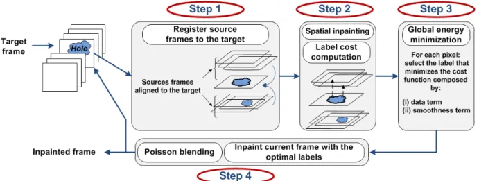
III. PROPOSED APPROACH
The proposed approach performs the inpainting of the input video sequence using a sliding temporal group of frames. As illustrated in figure 1, each frame is inpainted using two main steps: registration (step 1) and hole filling (step 2, 3 and 4). For each target frame It: R2→ R3with a hole Ωt⊂ R2, we align
its neighboring frames. Each pixel in Ωtis inpainted using the
most similar collocated pixel value in the aligned neighboring frames. Once the target frame has been inpainted, the target frame is replaced in the GoP by the inpainted one. As in [13], two input binary mask are required to indicate the areas we want to remove and the foreground areas.
The following section describes in details the two aforemen-tioned steps, i.e. registration and hole filling.
A. Frames registration
This section is devoted to the first step of the algorithm which consists in aligning the neighboring source frames Is with the target frame It. An efficient registration
method is required since alignment errors can propagate and undermine the spatial and temporal coherency of the inpainted areas. In addition, the proposed registration method should be fast enough to provide a reduced complexity video inpainting algorithm. To achieve this goal, we propose a new homography-based registration to handle the alignment problem.
1) Homography-based registration: Existing homography-based registration methods usually proceed in two steps. Key points are first extracted from a pair of images. The homogra-phy transformation that maps the key points of these images is then estimated. To get a reliable homography estimation, it is required that both images are viewing the same plane from a different angle and are taken from the same camera.
The homography matrix is a homogeneous non-singular 3× 3 matrix providing an invertible mapping of points on the projective plane [36]. Let ˜Istbe the mapping result of a source
frame Is into a target frame It. The homography matrix Hst
must satisfy : ∀p ∈ Is, ∃p0 ∈ ˜Ist s.t.
p0= Hstp (1)
To register two natural images which are most of the time composed of more than one plane, a single homography cannot provide an accurate alignment for all pixels. A better approach, when dealing with different view changes and camera motions, is to consider one homography for each pixel in the image. Existing homography-based alignment methods strive to de-termine the best homography transformation on a pixel-by-pixel basis. Homography candidates are recursively estimated between the source and target images [11], [13], [14], [34]. Algorithm 1 presents the pseudo-code of this method.
Algorithm 1: MRF-based registration input : It, Is
output: ˜Ist
% Extraction of the feature points Ft0← f eaturesExtract (It)
Fs0← f eaturesExtract (Is)
% Identification of potential feature correspondences {Ft, Fs} ← computeF undamentalM atrix(Ft0, Fs0)
% Initialization Hall← ∅
i ← 0
% Loop over features points while (enoughF eatureP oints) do
% Compute homography Hi and output unreliable
key points
{Hi, outliers} ← computeHomography(Ft, Fs)
% Append the homography Hi to the set Hall
Hall← Hall∪ Hi
% Keep only the unreliable feature points for a further processing
Ft← outliers(Ft)
Fs← outliers(Fs)
i ← i + 1 end
% Choose, among the set of homographies, the best one % with respect to the global energy function ξ() Hst← optimize (Hall, ξ(Hall))
% Perform the registration ˜
Ist← register (Is, Hst)
At each iteration, a homography matrix is estimated from the correspondences between the sets of key points. Outliers are identified and removed from the estimation. At the next iteration, the set of key points corresponding to outliers is used to compute a new homography matrix. The algorithm iterates until all pixels are associated to a given homography matrix. Finally, for each pixel p, the homography transformation that minimizes the global energy function ξ is chosen. For each
pixel p and homography candidate Hi, the energy function ξ
is defined as: ξ(Hi) = X p∈Is Ed(Hip) + α X p∈Is q∈N (p) Es(p, q), (2)
where, the data term Ed represents the registration errors
while the smoothness term Es helps reducing discrepancy
between neighboring pixels (p, q) and therefore enforces them to be registered using the same homography candidate. The parameter α is a positive constant that controls the trade-off between both terms. By default, α = 10.
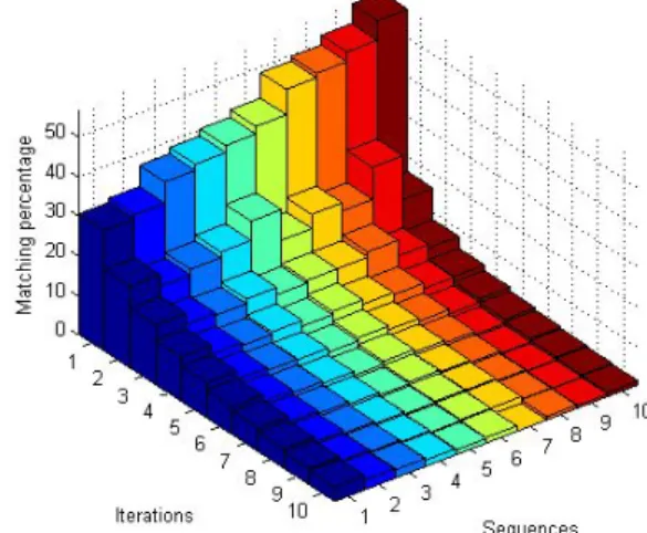
2) Analysis of homography-based registration: We first an-alyze homography-based registration with ten moving camera video sequences1 with different motion characteristics (i.e.
slow/fast view change, zooming, camera jitters).
Fig. 2: Percentage of matched features for 10 video sequences in function of the number of iterations i (see Algorithm 1).
Figure 2 shows, for each iteration of the algorithm, the percentage of matched feature points between each pair of frames distant by 10 frames in the sequence. This percentage simply represents the number of matched feature points used to compute the homography Hiat the iteration i. Results indicate
that five homography transformations allow us to warp more than 80% of the pixels whereas an unique transformation just warps between 30% and 60% of the pixels.
Figure 3 illustrates the homography-based registration re-sults when the RANSAC algorithm [37], [38] and the expansion-move algorithm [24], [25], [39] are used. The latter is used to globally minimize the energy function which is here defined by a data term and a smoothness term. The data term is related to the registration error between two images I1
and I2 (Ed(p) = I1(p) − ˜I2(p) 2 with ˜I2 = HiI2) while
the smoothness term is based on the discrepancy between two neighboring pixels (see Equation 5 which is defined in section III-B). Five iterations are used in the optimization algorithm. As illustrated by Figure 3, we observe that, when the motion between the two images is small (first row), the
JOURNAL OF LATEX CLASS FILES, VOL. 11, NO. 4, JANUARY 2014 5
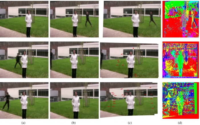
(a) (b) (c) (d)
Fig. 3: Alignment results using MRF-based registration optimization, under different motion conditions: low motion (first row), fast motion (second and third row). (a) Target image; (b) Source image; (c) Alignment result of the source to the target image; (d) Labels of homographies used to register each pixel in the source image. Red arrows indicate the most important errors.
method yields good alignment results. However, when there is a zoom or when the camera motion is fast and causes important viewpoint changes (second and third rows of Figure 3), the alignment errors drastically increase. This is especially true for regions corresponding to moving objects, as illustrated by Figure 3. In order to shed light on this observation, Figure 3 (d) gives a color representation in which one color corresponds to a particular homography transformation. When the motion is small (first row of Figure 3), a rather good segmentation of the image plane is obtained indicating that only one homography matrix is used per plane (such as the grass represented in red and the left-hand background in green). However, when the motion increases, the number of homographies used per plane becomes much higher. Due to the lack of homography transformations consistency used for pixels belonging to similar regions, the alignment quality is less stable and less reliable.
3) Proposed region-based registration approach: The pro-posed method aims at being well suited for various viewpoint changes and motion characteristics, while being fast enough to be reasonably considered as a preprocessing step in video editing algorithms.
The proposed region-based registration approach is moti-vated by the recent registration approach proposed in [40]. Assuming that the image pair is composed of two dominant planes, Gao et al. [40] perform the alignment by using only two homography transformations. First, SIFT features are extracted [41] and clustered into two groups based on their
Fig. 4: Overview of the proposed registration approach. The source image is first segmented into large regions. Each region is then registered according to the target image. Warped regions are then merged together.
spatial positions in the image [42]. Two homography transfor-mations that map each feature group are computed. These two homography transformations are then linearly combined. The weight of the linear combination controls on a pixel-basis the contribution of each homography and depends on the spatial proximity of the closest feature points.
The key idea is that neighboring pixels with similar features have to be aligned using the same homography transformation. This constraint is also used in MRF-based homographies meth-ods thanks to the smoothness term but the spatial consistency is limited to the chosen neighborhood (i.e. 4-neighbors are usually used). To ensure a higher spatial consistency, we use a spatial segmentation to determine homogeneous regions.
Assuming that a plane is homogeneous in terms of color, such regions may correspond to the actual planes of the scene. For this purpose, the mean-shift algorithm [43], which is a fast and automatic segmentation tool, requiring only few parameters such as the minimum size of a region, is used. Thanks to this segmentation, we are able to establish reliable correspondences between features points.
Figure 4 shows the main steps of the proposed registration method. The source image Is is first segmented into
homoge-neous regions using the mean-shift algorithm [43]. Examples of frame segmentation results are presented in Figure 5. Note that the regions must be large enough to detect a sufficient number of key points for the correspondence matching.
In a second step, the homography transformation is esti-mated for mapping each region of Is into the target frame
It. As in [44], to improve the registration process, the
ho-mography transformations, for which the matrix determinant is outside of the range [0.7, 3], are discarded. The range has been experimentally chosen. The set of homography transfor-mations is called Hall (see Algorithm 1). The union of all
aligned regions forms the registration of Is to It (noted by
Ist). Overlapping regions are averaged. Pixels which are not
covered by any regions (see for instance the white parts on the left-hand side of the woman in the second row and last column of Figure 6) are not considered in the subsequent operations of the inpainting process. In some cases, it may be possible that the set of homography transformations Hallis null. In this
case, we use a rigid transformation computed from two sets of sparse features that have been matched by the iterative Lucas-Kanade method with pyramids [45]. This method is efficiently used in several computer vision applications, such as video stabilization2.
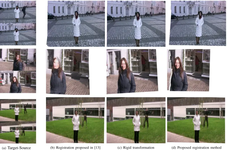
Registration results obtained with the proposed method are shown in Figure 6 and compared to the approach described in [13] and to a rigid transformation (i.e. translation and rotation) [46]. Note that the method in [13] uses an epipolar constraint to improve the registration quality. However, we can observe in Figure 6, that this constraint does not necessarily have a strong impact on the video inpainting quality. Results show that the proposed registration approach presents much less artifacts. Performing the registration of each region of the source image separately, by using a single homography transformation, helps to make the alignment better suited for various viewpoint changes.
B. Hole filling
Once the neighboring frames have been aligned, they form a stack of images from which the inpainting of missing areas is performed. To get spatio-temporal consistency, missing areas of frame Itare inpainted by minimizing globally (for all pixels
in Ωt) an energy function that expresses this consistency. In
other words, each pixel p in the hole Ωt∈ Itis inpainted using
the best collocated pixel value in the 2M registered frames ˜
Ii, i = 1 · · · 2M . There are M past and future neighboring
frames. We draw the reader’s attention to the fact that the M past neighboring frames have already been inpainted.
2See a demonstration and the source code on http://nghiaho.com/?p=2093.
Fig. 5: Segmentation results using Mean-Shift [43]. First row : original images; Second row : images with segmented regions.
Let L∗(p) be the labeling of the best pixel value collocated to p. This label indicates the registered frame ˜IL∗(p) from
which the pixel p has to be copied. L∗ is obtained by minimizing the following cost function defined over all pixels in Ωt: L∗ = arg min L ξ(L) (3) with ξ(L) = X p∈Ωt Ed(L(p)) + α X (p,q)∈N (Ωt) Es(L(p), L(q)) where,
• The first term of the energy cost, i.e. Ed(L(p)) called the
data term, expresses the stationarity of the background information at pixel p. The data term Ed(l) is the sum
of three terms (l is the label L(p) at pixel p):
Ed(l) = E0( ˜Il) + E1( ˜Il) + E2( ˜Il) (4)
where
– E0( ˜Il) = log(1 + M SE(It, ˜Il)) is the MSE (Mean
of Squared Differences) between the aligned neigh-boring frames ˜Il (l ∈ [t − M · · · t + M ]) and the
current target frame It. This term favors the pixel
that belongs to the best aligned frame, or saying differently the pixel having the lowest alignment error. The logarithm is used to limit the dynamic range of this term.
– The term E1( ˜Il) is a stationary term as
E1( ˜Il) = 1 2M |Ψl| M X j=−M kΨl− Ψjk2
where Ψlis the patch centered on the pixel p in the
aligned frame ˜Iland |Ψl| is its number of pixels. In
this way, we consider that most probable background pixel values among the possible labels are those which are the most redundant. This term enforces temporal coherence in the inpainted result. Moreover, computing this redundancy on the patch centered on p instead of computing it on the pixel basis makes the approach more robust to noise and illumination variations.
JOURNAL OF LATEX CLASS FILES, VOL. 11, NO. 4, JANUARY 2014 7
(a) Target-Source (b) Registration proposed in [13] (c) Rigid transformation (d) Proposed registration method
Fig. 6: Comparison of registration quality with scenes having different types of camera motion. First row: slow rotation; Second row: fast view changes; Third row: small view change and zooming. The columns represent: (a) Target and source images are illustrated on top and bottom, respectively; (b) MRF-based registration with epipolar constraints as in [13]; (c) registration using a rigid transform and (d) the proposed method. – The term E2( ˜Il) = Is(p) − ˜Il(p) 2 is a predicted term and represents the similarity of the candidate pixel value to the guiding initialization Is(p). The
initialization value Is is obtained by performing a
spatial inpainting of the hole in the target frame It.
This will be discussed in details in section III-C. This term contributes to improve spatial and temporal coherence of the inpainted result. When the pixel is missing in all the registered frames, the spatial initialization value is considered for inpainting. This case occurs at the beginning of the video sequence and after scene cuts.
• The last term of the energy function, presented in equa-tion 3, is a smoothness term defined on each pair of neighboring pixels (p and q) in the hole as follows:
Es(a, b) = ˜ Ia(p) − ˜Ib(p) 2 + ˜ Ia(q) − ˜Ib(q) 2 (5) This term ensures that the pixel value used to inpaint each hole pixel should be similar to the ones used to inpaint its neighboring pixels. This consistency is achieved by inpainting each two neighboring pixels with the same registered frame. This term enhances the spatial consistency by preventing incoherent seams.
• The quantity N refers to the 4-neighbors of the pixel p.
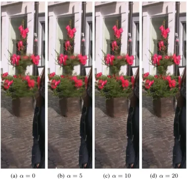
The parameter α is a positive constant that controls the trade-off between both terms. As illustrated by Figure 8, α = 10 is a good trade off between the data and the smoothness term (see Figure 8 (c)). When α = 0 (see Figure 8 (a)), there is a lack of spatial consistency.
(a) (b) (c)
Fig. 7: Influence of the spatial inpainting methods on the final result: (a) Original image + mask; (b) Inpainting result when initializing with interpolation [15]; (c) Inpainting result when initializing with the spatial inpainting method described in [47].
Compared to methods proposed in [13]–[15] which consider a data term based only on the similarity of each pixel candidate to the collocated initialization term (as E2 in
Equation 4), the proposed formulation which combines this term (E2) with the error alignment (E0) and the temporal
consistency term (E1) allow us to select more consistent
labels, resulting in significant inpainting quality improvement. The minimization of Equation 3 is achieved by the expansion-move algorithm [24], [25], [39]. Five iterations are performed.
(a) α = 0 (b) α = 5 (c) α = 10 (d) α = 20
Fig. 8: Influence of the parameter α of equation 3: (a) when α = 0, there is no constraint of smoothness. Some blur appears due to the lack of spatial coherency. For (b), (c) and (d), the smoothness term allows to keep a better spatial consistency increasing the overall quality of the results. By default, we choose α = 10 which provides a good balance between the data and the smoothness terms (Frame 34 of Scene 1).
C. Initialization of predicted term: spatial inpainting As mentioned above, a coarse initialization, also called the predicted term (i.e. E2 in equation 4), is often used in
MRF-based inpainting methods to guide the temporal inpainting of missing pixels. Higher priority is then given to pixel values of the registered neighboring frames that are the most similar to the initialization prediction. In state-of-the-art methods, the predicted term may be obtained by a simple spatial interpola-tion [15], a median [11] or a weighted temporal interpolainterpola-tion of collocated pixels values in the registered images [13]. In this latter case, the missing pixels need to be known in at least one neighboring frame. This strategy is costly from a computational point of view. This indeed requires a large temporal window to ensure that each missing pixel is predicted by at least one unoccluded pixel value. In addition, this method is not appropriate for inpainting holes corresponding to almost static or slow moving objects in the scene. The use of a robust spatial inpainting to initialize the predicted term may relax this constraint by providing better results even if the missing hole is stationary all over the video.
We evaluate two methods: a simple spatial interpolation and a spatial inpainting method [47]. First, we consider the implementation of the spatial interpolation proposed in [15] as: I(p) = 1 Cw X p0∈W \Ω (1 − kp − p 0k2 |W | )I(p 0) (6)
where W is a window centered on p. Cw is a normalizing
factor. Figure 7 (b) shows that this coarse interpolation does not provide a high quality of inpainting. A better solution is to perform a spatial inpainting. For that, we re-implemented a recent spatial inpainting method which relies on the statistical distribution of patch offsets in the image [47]. We compute an Approximate Nearest Neighbors Field (ANNF) using the Patch Match method [2]. From the ANNF, the 30 most principal modes of the distribution of patch offsets are extracted. A stitching of the shifted images (using the top 30 dominant offsets) is performed. Inpainting is finally obtained by mini-mizing a predefined energy cost [47]. Figure 7 (c) shows that video inpainting using an inpainting-based predicted term [47] provides better image quality than using a simple interpolation.
D. Poisson blending
Poisson image blending is a popular tool for seamless image cloning [48]. In our approach, we apply the Poisson blending to the inpainted result. Interestingly, the Poisson blending allows to strengthen the temporal consistency and to increase the robustness of the proposed approach as well. Indeed, once the blending has been performed, we replace the current image by the blended and inpainted image into the GoP, as illustrated by Figure 1. The subsequent image will be then inpainted by taking into account the previous blended and inpainted frames. Figure 9 illustrates the impact of the Poisson blending on the inpainted image. The quality of the inpainted image is improved when the Poisson blending is applied.
(a) (b)
Fig. 9: Influence of the Poisson blending: (a) without Poisson blending; (b) with Poisson blending.
IV. EXPERIMENTS RESULTS
We evaluate the performance of the proposed approach in three main applications: object removal, background estimation and error concealment. These three applications present different features. For object removal and error concealment, the spatial location of missing areas is known.
JOURNAL OF LATEX CLASS FILES, VOL. 11, NO. 4, JANUARY 2014 9
However, there is a difference in the shape of the missing areas. In the context of loss concealment, the geometric shape of missing areas is square or rectangle whereas the shape is arbitrary for object removal. Concerning the background estimation, there is no prior knowledge about the areas that should be inpainted. The inpainting method has to classify all pixels as belonging to the background or not. All the following results are obtained with the same configu-ration. The registration applied per region is achieved by using the SURF algorithm [49] with a Hessian threshold equal to 500 and the RANSAC algorithm [38]. Once the frames are aligned, the inpainting is performed by minimizing globally the energy function. The minimization is achieved by the expansion-move algorithm [24], [25], [39]. The sliding window is composed of 21(M = 10) frames and the minimal size of a region computed by the mean-shift algorithm is equal to 25% of the frame size. In average, the number of regions per frame is 2.7.
A. Object removal
The first experiments assess qualitatively the performance of the proposed method on a set of video sequences in a context of object removal.
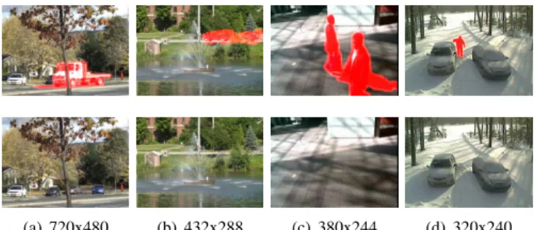
(a) 720x480 (b) 432x288 (c) 380x244 (d) 320x240
Fig. 10: Samples of change detection videos. Top row: images with the mask of the object to be removed. Bottom row: inpainting results using the proposed method for 5 scene categories: (a) and (b) Dynamic background; (c) Shadow; (d) Intermittent object motion. Results are given on the authors’ webpage in full spatio-temporal resolution.
1) Results obtained from Change Detection dataset: The change detection dataset3 has been initially designed to
benchmark change detection algorithms [50]. This dataset is composed of 31 real-world videos representing more than 80, 000 frames and spanning 6 categories selected to include diverse motion and change detection challenges. For all these sequences, a ground truth is provided in the form of binary maps indicating where the changes occur. We extract from this dataset several sequences corresponding to the following categories:
• baseline: this category contains simple videos without camera motion. Three video sequences have been used to test the proposed method namely Highway (325 frames of 320 × 240), Office (150 frames of 360 × 240) and pets2006 (500 frames of 720 × 576).
3http://changedetection.net/
• camera jitter: this category contains videos with heavy camera jitter. We use two video sequences, badminton (325 frames of 720 × 480) and traffic (230 frames of 320 × 240).
• dynamic background: video sequences of this category
exhibit dynamic background motion with complex tex-tures (for instance water). Four sequences have been tested, boats (150 frames of 320 × 240), fountain02 (140 frames of 432 × 288), canoe (300 frames of 320 × 240) and fall (475 frames of 720 × 480).
• intermittent object motion: it contains videos with back-ground objects moving away, abandoned objects and objects stopping for a short while and then moving away. Two video sequences have been selected namely sofa (400 frames of 320 × 240) and winterDriveway (420 frames of 320 × 240).
• shadow: this category contains video sequences with a lot
of shadow and illumination change. Two video sequences have been selected, busStation (400 frames of 360 × 240) and peopleInShade (250 frames of 380 × 244).
A total of 15 video sequences representing 4080 frames are then used to evaluate the performance of the proposed method. The object to remove is given by the ground truth (in the form of binary map). Note that the binary maps have been manually modified so that they fit well with the objects boundaries. The use of this set of video sequences is interesting since these input video sequences are very challenging showing camera shake (camera jitter category), illumination changes, indoor and outdoor scenes, different sizes of objects to be removed, stochastic textures, different levels of quality as well as resolution, etc.
Some results are presented in Figures 10 and 11. The proposed inpainting approach provides high quality results with different video textures and in presence of different kinds of motion.
2) Comparison with state-of-the art method: the second test consists in comparing the results of the proposed approach to Granados et al.’s method [13]. This comparison involves 5 video sequences with different camera motions. Each video sequence contains two or three dominants planes and one or two moving objects. A binary mask indicating the object to be removed from the scene is used. A second mask indicates foreground objects and aims to prevent the propagation of foreground information into the missing areas.
Results are illustrated in Figure 12. Figure 12 (a) shows the original images with the mask of the object to be removed. Figure 12 (b) and (c) illustrate Granados’s method and the pro-posed approach, respectively. We observe that the the propro-posed approach outperforms Granados’s method4. Although that this
video sequence presents a small view point variation which makes the alignment easier, one can remark that inpainting results of the method in [13] show several temporal artifacts that are not present with our method. This point is even more interesting given the fact that the proposed method only uses a small number of frames to inpaint the current frame.
4Videos sequences published by authors in [13] in http://www.mpi-inf.mpg. de/∼granados/projects/vidbginp/index.html
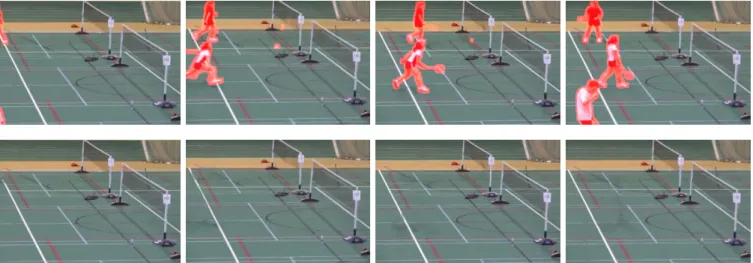
Fig. 11: Inpainting results (frames 11, 50, 68, 168) of the badminton video sequence (with camera jitter motion). Top row: original frames; Bottom row: our inpainting results.
(a) (b) (c)
Fig. 12: Comparison with Granado’s method [13] on the frames 38 and 74 of sequence scene3: (a) Original image+mask; (b) Granados’s inpainting results; (c) Inpainting results using the proposed approach. Differences are only visible on areas corresponding to the reddish areas appearing on (a).
Inpainted images with higher view point variations (such as Scene1 and Scene4) present a better quality with our approach than with Granados’s method [13]. Readers are invited to view the video sequences on the dedicated website (http://people.irisa.fr/Olivier.Le Meur/).
3) More experimental results: We test the proposed ap-proach when the registration uses a MRF-based registration or a rigid transform. Figure 13 shows that the inpainting quality significantly drops when a rigid transformation is used. Less alignment artifacts image per image does not necessarily implies better video inpainting results. The pixels in each
frame are aligned with the same transformation which limits the spatial artifacts (image per image) in the aligned frame. However, collocated pixels in neighboring frames may not have been aligned in a temporally coherent manner especially in cases of complex camera motions such as zooming or fast rotation. This is the reason why the inpainting results is not necessarily better. Another kind of test has been performed: as the complexity of the proposed method is not prohibitive, the inpainting can be applied in an iterative manner. The inpainted video sequence is simply reused as an input of the inpainting process. For the second and subsequent iterations, we disable
JOURNAL OF LATEX CLASS FILES, VOL. 11, NO. 4, JANUARY 2014 11
(a) (b)
(c) (d)
(e) (f) (g)
Fig. 13: Impact of the registration method on the inpainting quality. Once the frames in the GoP are aligned, they are filled using the optimization energy in Equation 3: (a) Original image + mask; (b) MRF-based registration approach; (c) Rigid transformation approach; (d) Proposed region-based registration approach; (e), (f) and (g) zoom in on the upper part of the building for (b), (c) and (d) approaches, respectively. In (e), red arrows indicate the most important artifacts.
the predicted term and directly used the inpainted results of the previous iteration as an initialization. This method allows us to improve upon the quality of the result. Video sequences are available on the dedicated website.
B. Background estimation
The proposed approach is also validated in a context of background estimation when the camera is static. This appli-cation can be considered as a non-parametric object removal application. We consider here a simple background estimation algorithm without any background model. For each frame It,
the mask of the moving objects (non static regions Ωt) in the
scene is first estimated using four distant neighboring frames (2 past and 2 futures frames). The proposed video inpainting technique is used to inpaint Ωt. As shown in Figure 15
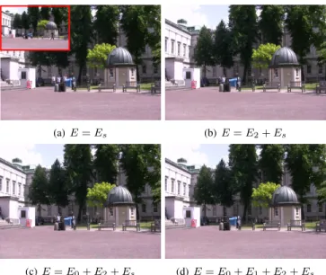
(second row), the non-static regions are the union of holes corresponding to moving objects in each considered frame. Background estimation results illustrated in Figure 14 show that the data term (Ed = E2) used in [13] does not lead
to a good background estimation. The best reconstruction is obtained when the data term consists of the terms E0,
E1 and E2. Furthermore, background estimation results of
(a) E = Es (b) E = E2+ Es
(c) E = E0+ E2+ Es (d) E = E0+ E1+ E2+ Es
Fig. 14: Background estimation using different data terms. For these tests, the smoothness term defined in Equation 5 is used. The original image (frame 40) is shown at top-left side of (a).
(a) Frame 0 (b) Frame 120 (c) Frame 240
Fig. 15: Background estimation. Top row: original video sequence; Middle row: estimated non static regions in red corresponding to holes to be inpainted; Bottom row: inpainted results.
different frames illustrated in Figure 15 show that the proposed approach provides background reconstruction results with a higher space-time consistency.
C. Error concealment
To further evaluate the performances of the proposed ap-proach, we evaluate the inpainting quality results in a context of error concealment. In this test, we consider three videos5
(Scene11, Scene12 and Scene13) with different types of camera motion (zooming, camera jittering and small rotation, respectively). These video sequences have been used to vali-date a stabilization method recently proposed by [34]. The sequences contain respectively 435, 250 and 360 frames.
(a) (b) (c)
Fig. 16: Sample frames from videos considered for error conceal-ment. (a) Scene11; (b) Scene12; (c) Scene13. From top to bottom: Original frames; Frames with the missing blocks; Inpainting results using the proposed approach.
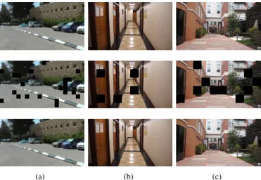
As summarized in Table I, we consider three loss rates (5%, 10% and 20%) of 64 × 64 blocks for each video sequence (see Figure 16). The inpainting has been tested in function of the number of regions used to perform the frames registration. As we are in a loss concealment context, it is possible to objectively evaluate the quality of the reconstruction. For that, we compute the PSNR between the original video sequence and the inpainted one. Several conclusions can be drawn from the results given in Table I. First, the number of regions used in the registration method plays an important role. The worst quality is obtained when a single homography is used. The gain, in terms of PSNR, significantly increases when several regions are considered. The gain is up to 3dB especially when the camera motion is complex (zooming and camera jittering). For simple camera motion such as small rotation for the sequence Scene13, the gain brought by the use of several regions is less significant but still positive compared to the results obtained by a unique homography. When the number of regions increases (more than 4), we observe a loss of performance for the sequence Scene12 which presents camera shake and jittering. These results indicate that the number of regions could be adapted according to the complexity of the camera motion. For rotations and small translations, the number of regions can be relatively high whereas, when there are brutal changes in the video, it is better to favor a small number of regions. In our approach we recommend that the region size should be at least equal to 25% of the image size. We also compare the quality of the reconstruction when either the proposed inpainting method or the spatial initializa-tion applied frame-by-frame is considered. We remind that the spatial initialization is obtained by our own implementation of the method proposed by [47]. This method is called Spatial init. (ANN)in Table I. The proposed inpainting method clearly outperforms the spatial initialization. As expected, this test demonstrates that spatial inpainting can not reconstruct effi-ciently the missing areas. A more complex process, involving the neighboring frames and a global minimization of an energy
(as the one defined by Equation 3) is required. Note also that the initialization step used in the proposed approach plays an important role, as illustrated in previous sections, but, taken alone, it cannot provide good results.
D. Running time
Table II gives the running time of the proposed approach per frame for different video sequences. The software is written in C++. Simulations have been performed on a laptop with an Intel Core i7 2.67GHz and 4Go RAM. As the proposed approach is not multi-threaded, it just uses one core. In addition, no optimization was made.
E. Limitations
The proposed inpainting approach shows some limitations. The first limitation is due to the fact that the video inpainting is performed on short-term windows. Therefore, when the object to remove is static or quasi static, the proposed method may fail to fill in the missing pixels in a coherent manner. Indeed, in that particular case, almost all missing pixels are estimated using the spatial inpainting which does not ensure temporal coherence and still suffers from some spatial artifacts. One solution to deal with this problem is to increase the size of the sliding temporal window. The ultimate solution is to consider all frames of the video sequences as in [10], [13].
A second limitation concerns the image registration. Homography-based registration does not yield good perfor-mance when there are not enough feature points in the images. This occurs when the video sequence is smooth without textural information. In this case, usually a single plane within the scene is found which is a clear limitation for the proposed approach. Additionally, the video scenes should be parallax-free to correctly compute the homography matrix transforming a set of features in one image into the corresponding features in the second image. To overcome this problem, the proposed homography-based registration could be coupled with a dense non-parametric correspondences method.
V. CONCLUSION
We propose a novel video inpainting method. In a first step, neighboring frames are registered with a region-based homography. Each plane in the scene is assimilated to a ho-mogeneous region segmented using the mean-shift algorithm. Inpainting is then performed using a predefined energy cost which is globally minimized. A spatial inpainting is used to guide this minimization leading to improve the quality of the inpainted areas. The proposed approach has a reduced complexity compared to existing methods. Missing areas are filled in by considering less than 20 frames that belongs to a sliding window. Unlike Granados et al.’s method [13], in which three optimization steps are involved (homography computa-tion, inpainting and illumination handling), our approach uses only two global optimization methods and uses as mentioned previously a reduced number of frames.
Experiments show that the proposed approach provides high quality inpainting results. Future work will focus on inpainting both background and moving objects in the videos.
JOURNAL OF LATEX CLASS FILES, VOL. 11, NO. 4, JANUARY 2014 13
TABLE I: PSNR values of inpainted videos in function of region numbers and percentage of loss.
Scene11 Scene12 Scene13
Percentage of loss
(1280 × 720) (640 × 360) (640 × 360)
Average number Spatial Average number Spatial Average number Spatial
of regions/frame init. (ANN) of regions/frame init. (ANN) of regions/frame init. (ANN)
1 2.32 4.54 – 1 2.44 4.9 – 1 2.45 4.67 –
5% 27.97 30.9 31.14 19.67 30.08 32.01 23.94 19.1 28.47 28.7 28.75 17.47
10% 27.84 30.63 30.84 21.24 30.32 31.45 26.97 17.75 28.59 28.98 29.05 16.95
20% 27.47 30.06 30.27 19.29 29.28 31.02 24.3 17.75 28.16 28.6 28.79 16.97
TABLE II: Average running time (in second) per frame in function of the number of missing pixels (legend: Res.=Resolution;Reg.=Number of Regions;Seg.=segmentation; Inp.=Inpainting).
Video Res. Frames Missing Reg. Seg. Inp.
number pixels (sec.) (sec.)
1440 × 1056 180 16% 2.35 2.71 88 960 × 720 270 9% 2.54 1.42 37 960 × 720 225 9% 2.92 1.44 37 960 × 720 220 11% 2.68 1.98 34 1440 × 1056 480 13% 3.03 2.86 99 REFERENCES
[1] C. Guillemot and O. Le Meur, “Image inpainting: Overview and recent advances,” IEEE Signal Process. Magazine, Jan. 2014.
[2] C. Barnes, E. Shechtman, A. Finkelstein, and D. B. Goldman, “Patch-match: a randomized correspondence algorithm for structural image editing,” ACM Trans. on Graphics, vol. 28, no. 3, pp. 24:1–24:11, Jul. 2009.
[3] D. Glasner, S. Bagon, and M. Irani, “Super-resolution from a single image,” in IEEE Int. Conf. on Comput. Vis., 2009, pp. 349–356. [4] J. Apostolopoulos, W. Tan, and S. Wee, “Video streaming: concepts,
algorithms and systems,” HP Laboratories Palo Alto, Tech. Rep., 2002. [5] Y. Matsushita, E. Ofek, W. Ge, X. Tang, and H.-Y. Shum, “Full-frame video stabilization with motion inpainting,” IEEE Trans. on Pattern Anal. and Mach. Intell., vol. 28, no. 7, pp. 1150–1163, Jul. 2006. [6] K. A. Patwardhan, G. Sapiro, and M. Bertalmio, “Video inpainting under
constrained camera motion,” IEEE Trans. on Image Process., vol. 16, no. 1, pp. 545–553, Jan. 2007.
[7] T. K. Shih, N. C. Tang, and J.-N. Hwang, “Exemplar based video inpainting without ghost shadow artifacts by maintaining temporal continuity,” IEEE Trans. Circuits Syst. Video Techn., vol. 19, no. 3, pp. 347–360, Mar. 2009.
[8] T. K. Shih, N. C. Tan, J. C. Tsai, and H.-Y. Zhong, “Video falsifying by motion interpolation and inpainting,” in Int. Conf. on Comput. Vis. and Pattern Recognit., 2008, pp. 1–8.
[9] Y. Wexler, E. Shechtman, and M. Irani, “Space-time completion of video,” IEEE Trans. on Pattern Anal. and Mach. Intell., vol. 29, no. 3, pp. 463–476, Mar. 2007.
[10] A. Newson, A. Almansa, M. Fradet, Y. Gousseau, and P. P´erez, “Video inpainting of complex scenes,” SIAM Journal of Imaging Science, vol. 7, no. 4, pp. 1993–2019, 2014.
[11] O. Whyte, J. Sivic, and A. Zisserman, “Get out of my picture! internet-based inpainting,” in British Mach. Vis. Conf., 2009, pp. 1–11. [12] W.-Y. Lin, S. Liu, Y. Matsushita, T.-T. Ng, and L. F. Cheong, “Smoothly
varying affine stitching,” in Int. Conf. on Comput. Vis. and Pattern Recognit., 2011, pp. 345–352.
[13] M. Granados, J. Tompkin, K. Kim, O. Grau, J. Kautz, and C. Theobalt, “Background inpainting for videos with dynamic objects and a free-moving camera,” in Eur. Conf. on Comput. Vis., 2012, pp. 682–695. [14] S. Liu, L. Yuan, P. Tan, and J. Sun, “Bundled camera paths for video
stabilization,” ACM Trans. on Graphics, vol. 32, no. 4, pp. 78:1–78:10, Jul. 2013.
[15] X. Chen, Y. Shen, and Y. H. Yang, “Background estimation using graph cuts and inpainting,” in Graphics Interface, 2010, pp. 97–103. [16] S. Cohen, “Background estimation as a labeling problem,” in IEEE Int.
Conf. on Comput. Vis., 2005, pp. 1034–1041.
[17] A. Criminisi, P. P´erez, and K. Toyama, “Region filling and object removal by exemplar-based image inpainting,” IEEE Trans. on Image Process., vol. 13, no. 9, pp. 1200–1212, Sep. 2004.
[18] P. Buyssens, M. Daisy, D. Tschumperl´e, and O. L´ezoray, “Exemplar-based Inpainting: Technical Review and new Heuristics for better Geometric Reconstructions,” IEEE Transactions on Image Processing, vol. 24, no. 6, pp. 1809 – 1824, 2015. [Online]. Available: https://hal.archives-ouvertes.fr/hal-01147620
[19] O. Le Meur and C. Guillemot, “Super-resolution-based inpainting,” in Eur. Conf. on Comput. Vis., 2012, pp. 554–567.
[20] O. Le Meur, M. Ebdelli, and C. Guillemot, “Hierarchical super-resolution-based inpainting,” IEEE Trans. on Image Process., vol. 22, no. 10, pp. 3779–3790, Sep. 2013.
[21] Y. Hu and D. Rajan, “Hybrid shift map for video retargeting,” in Int. Conf. on Comput. Vis. and Pattern Recognit., 2010, pp. 577–584. [22] Y. Pritch, E. Kav-Venaki, and S. Peleg, “Shift-map image editing,” in
IEEE Int. Conf. on Comput. Vis., 2009, pp. 151–158.
[23] V. Kwatra, A. Schdl, I. A. Essa, G. Turk, and A. F. Bobick, “Graphcut textures: image and video synthesis using graph cuts,” in ACM Trans. on Graphics, 2003, pp. 277–286.
[24] V. Kolmogorov and R. Zabih, “What energy functions can be minimized via graph cuts?” IEEE Trans. on Pattern Anal. and Mach. Intell., vol. 26, no. 2, pp. 147–159, Feb. 2004.
[25] Y. Boykov, O. Veksler, and R. Zabih, “Fast approximate energy mini-mization via graph cuts,” IEEE Trans. on Pattern Anal. and Mach. Intell., vol. 23, no. 11, pp. 1222–1239, Nov. 2001.
[26] J. Odobez and P. Bouthemy, “Robut multiresoltuion of parametric motion models,” Journal of Visual Communication and Image Repre-sentation, vol. 6, no. 4, pp. 348–365, 1995.
[27] C.-H. Ling, C.-W. Lin, C.-W. Su, H.-Y. M. Liao, and Y.-S. Chen, “Video object inpainting using posture mapping,” in IEEE Int. Conf. on Image Process., 2009, pp. 2785–2788.
[28] J. Jia, Y.-W. Tai, T. Wu, and C.-K. Tang, “Video repairing under variable illumination using cyclic motions,” IEEE Trans. on Pattern Anal. and Mach. Intell., vol. 28, no. 5, pp. 832–839, May 2006.
[29] M. V. Venkatesh, S. S. Cheung, and J. Zhao, “Efficient object-based video inpainting,” Pattern Recognition Letters, vol. 30, no. 2, pp. 168– 179, Jan. 2009.
[30] R. Szeliski, “Image alignment and stitching: A tutorial,” Found. Trends. Comput. Graph. Vis., vol. 2, no. 1, pp. 1–104, Jan. 2006.
[31] A. Hosny, C. Rhemann, M. BLeyer, and M. Gelautz, “Temporally con-sistent disparity and optical flow via efficient spatio-temporal filtering,” PSIVT, Springer, Lecture Notes in Computer Science, vol. 7087, pp. 165–177, 2011.
[32] M. Hoffken, D. Oberhoff, and M. Kolesnik, “Temporal prediction and spatial regularization in differential optical flow,” ACIVS, Springer, Lecture Notes in Computer Science, vol. 6915, pp. 576–585, May 2011. [33] S. Volz, A. Bruhn, L. Valgaerts, and H. Zimmer, “Modeling temporal coherence for optical flow,” in Proc. 13th Int. Conf. on Computer Vision (ICCV), 2011, pp. 1116–1123.
[34] Z. Zhou, H. Jin, and Y. Ma, “Plane-based content preserving warps for video stabilization,” in Int. Conf. on Comput. Vis. and Pattern Recognit., 2013, pp. 2299–2306.
[35] R. Toldo and A. Fusiello, “Robust multiple structures estimation with j-linkage,” in Eur. Conf. on Comput. Vis., 2008, pp. 537–547. [36] R. I. Hartley and A. Zisserman, Multiple View Geometry in Computer
Vision, 2nd ed. Cambridge University Press, 2004.
[37] M. A. Fischler and R. C. Bolles, “Random sample consensus: A paradigm for model fitting with applications to image analysis and
automated cartography,” Commun. of the ACM, vol. 24, no. 6, pp. 381– 395, 1981.
[38] J. J. Lee and G. Y. Kim, “Robust estimation of camera homography using fuzzy ransac,” in Int. Conf. on Computational Science and Its Applications, 2007.
[39] Y. Boykov and V. Kolmogorov, “An experimental comparison of min-cut/max-fow algorithms for energy minimization in vision,” IEEE Trans. on Pattern Anal. and Mach. Intell., vol. 26, no. 9, pp. 1124–1137, Sep. 2004.
[40] J. Gao, S. Kim, and M. Brown, “Constructing image panoramas using dual-homography warping,” in Int. Conf. on Computer Vision and Pattern Recognition (CVPR), 2011, pp. 49–56.
[41] D. G. Lowe, “Distinctive image features from scale-invariant keypoints,” International Journal of Computer Vision, vol. 60, pp. 91–110, 2004. [42] M. Brown and D. Lowe, “Automatic panoramic image stitching using
invariant features.” International Journal of Computer Vision, vol. 74, no. 1, pp. 59–73, 2007.
[43] D. Comaniciu and P. Meer, “Mean shift: a robust approach toward feature space analysis,” IEEE Trans. on Pattern Anal. and Mach. Intell., vol. 24, no. 5, pp. 603–619, May 2002.
[44] E. Vincent and R. Lagani´ere, “Detecting planar homographies in an image pair,” in Image and Signal Processing and Analysis, 2001, pp. 182–187.
[45] B. D. Lucas and T. Kanade, “An iterative image registration technique with an application to stereo vision,” in Image Understanding workshop, 1981, pp. 121–130.
[46] L. G. Brown, “A survey of image registration techniques,” ACM Comput. Surv., vol. 24, no. 4, pp. 325–376, Dec. 1992. [Online]. Available: http://doi.acm.org/10.1145/146370.146374
[47] K. He and J. Sun, “Statistics of patch offsets for image completion,” in Eur. Conf. on Comput. Vis., 2012, pp. 16–29.
[48] P. P´erez, M. Gangnet, and A. Blake, “Poisson image editing,” ACM Trans. Graph., vol. 22, no. 3, pp. 313–318, Jul. 2003. [Online]. Available: http://doi.acm.org/10.1145/882262.882269
[49] H. Bay, T. Tuytelaars, and L. V. Cool, “Speed-up robust features(surf),” Comput. Vis. and and Image Understanding, vol. 110, no. 3, pp. 346– 359, Jun. 2008.
[50] N. Goyette, P.-M. Jodoin, F. Porikli, J. Konrad, and P. Ishwar, “Changedetection.net: A new change detection benchmark dataset.” in Int. Conf. on Comput. Vis. and Pattern Recognit. Workshops, 2012, pp. 1–8. [Online]. Available: http://changedetection.net/
Mounira Ebdelli received the engineering degree from ENSI (Ecole Nationale des Sciences de lIn-formatique), Tunisia, in 2005 and the M.Sc. degree in computer sciences from Paris Descartes, France, in 2009. She holds a PhD degree from University of Rennes with the SIROCCO Research Group, INRIA, Rennes, France, in 2014. From Nov. 2005 to Oct. 2008, she has worked as an application engineer in STMicroelectronics, Tunisia. From Oct. 2008 to Dec. 2010, she was a Teacher with the High Institute of Technological Studies in Tunisia. Her research interests include signal processing with an emphasis on image and video processing.
Olivier Le Meur obtained his PhD degree from the University of Nantes in 2005. From 1999 to 2009, he has worked in the media and broadcasting industry. In 2003 he joined the research center of Thomson-Technicolor at Rennes where he super-vised a research project concerning the modelling of the human visual attention. Since 2009 he has been an associate professor for image processing at the University of Rennes 1. In the IRISA/SIROCCO team his research interests are dealing with the un-derstanding of the human visual attention. It includes computational modelling of the visual attention and saliency-based applica-tions (video compression, objective assessment of video quality, retargeting). Home page: http://people.irisa.fr/Olivier.Le Meur/.
Christine Guillemot is Director of Research at INRIA, head of a research team dealing with image and video modelling, processing, cod-ing and communication. She holds a PhD de-gree from ENST (Ecole Nationale Sup´erieure des T´el´ecommunications) Paris, and an ’Habilitation for Research Direction’ from the University of Rennes. From 1985 to Oct. 1997, she has been with FRANCE TELECOM, where she has been involved in various projects in the area of image and video coding for TV, HDTV and multimedia. From Jan. 1990 to mid.1991, she has worked at Bellcore, NJ, USA, as a visiting scientist. She has (co)-authored 15 patents, 8 book chapters, 50 journal papers and 140 conference papers. She has served as associated editor (AE) for the IEEE Trans. on Image processing (2000-2003), for IEEE Trans. on Circuits and Systems for Video Technology (2004-2006) and for IEEE Trans. on Signal Processing (2007-2009). She is currently AE for the Eurasip journal on image communication, for IEEE Trans. on Image Processing and member of the editorial board of the IEEE Journal of Selected Topics in Signal Processing.. She has been a member of the IEEE IMDSP and MMSP technical committees. Home page http://people.rennes.inria.fr/Christine.Guillemot/.
![Figure 4 shows the main steps of the proposed registration method. The source image I s is first segmented into homoge-neous regions using the mean-shift algorithm [43]](https://thumb-eu.123doks.com/thumbv2/123doknet/12577021.346396/7.918.472.843.86.281/figure-proposed-registration-method-source-segmented-regions-algorithm.webp)