IEEE Proof
Web Version
IEEE TRANSACTIONS ON NUCLEAR SCIENCE 1
Improved LabPET Detectors Using
(LGSO) Scintillator Blocks
Mélanie Bergeron, Student Member, IEEE,
Catherine M. Pepin, Jules Cadorette, Francis Loignon-Houle, Réjean Fontaine, Senior Member, IEEE, and
Roger Lecomte, Senior Member, IEEE
Abstract—The scintillator is one of the key building blocks that
critically determine the physical performance of PET detectors. The quest for scintillation crystals with improved characteristics has been crucial in designing scanners with superior imaging performance. Recently, it was shown that the decay time con-stant of high lutetium content (LGSO) scintillators can be adjusted by varying the cerium concentra-tion from 0.025 mol% to 0.75 mol%, thus providing interesting characteristics for phoswich detectors. The high light output (90%–120% NaI) and the improved spectral match of these scintillators with avalanche photodiode (APD) readout promise superior energy and timing resolutions. Moreover, their improved mechanical properties, as compared to conventional LGSO ( ), make block array manufacturing readily feasible. To verify these assumptions, new phoswich block arrays made of LGSO-90%Lu with low and high mol% Ce con-centrations were fabricated and assembled into modules dedicated to the LabPET scanner. Typical crystal decay time constants were 31 ns and 47 ns, respectively. Phoswich crystal identification performed using a digital pulse shape discrimination algorithm yielded an average 8% error. At 511 keV, an energy resolution of 17–21% was obtained, while coincidence timing resolution between 4.6 ns and 5.2 ns was achieved. The characteristics of this new LGSO-based phoswich detector module are expected to improve the LabPET scanner performance. The higher stopping power would increase the detection efficiency. The better timing resolution would also allow the use of a narrower coincidence window, thus minimizing the random event rate. Altogether, these two improvements will significantly enhance the noise equivalent count rate performance of an all LGSO-based LabPET scanner.
Index Terms—Avalanche photodiodes, energy resolution,
LabPET, LGSO, positron emission tomography, scintillators, small-animal PET scanner, timing resolution.
Manuscript received September 15, 2014; revised November 21, 2014; ac-cepted December 28, 2014. This work was supported by Grants from the Natural Science and Engineering Research Council of Canada (NSERC), the Canadian Institutes of Health Research (CIHR), and Fonds de recherche du Québec
-Na-ture et technologies (FRQNT). The Sherbrooke Molecular Imaging Center is a
member of the FRSQ-funded Centre de Recherche du Centre hospitalier
uni-versitaire de Sherbrooke (CHUS).
M. Bergeron, C. M. Pepin, J. Cadorette, F. Loignon-Houle, and R. Lecomte are with the Sherbrooke Molecular Imaging Centre of CRCHUS and the Department of Nuclear Medicine and Radiobiology, Université de Sherbrooke, Sherbrooke, Québec, Canada (e-mail: [email protected]; [email protected]; [email protected]; [email protected]; [email protected]).
R. Fontaine is with the Department of Electrical Engineering and Computer Engineering, Université de Sherbrooke, Sherbrooke, Québec, Canada (e-mail: [email protected]).
Color versions of one or more of the figures in this paper are available online at http://ieeexplore.ieee.org.
I. INTRODUCTION
S
CINTILLATORS largely determine the basic performance of PET scanners. Expectedly, major efforts have been com-mitted to discover new scintillation materials, and also to im-prove characteristics of existing ones, such as stopping power, light output and emission decay time [1]–[4]. For instance, time-of-flight PET, which inherently needs an outstanding timing res-olution, prompted the search for new scintillators with higher light yield combined with faster decay time [5], [6]. In addi-tion, better timing and energy resolution for PET support the development of applications using lower energy radiation such as SPECT (140 keV) and CT ( keV).New high lutetium content
(LGSO-90%Lu) scintillators with high light output (90–120% NaI) and tunable fast decay times were recently introduced [7], [8]. The range of decay times from 31 to 47 ns, which can be adjusted by varying the Ce concentration from 0.025 to 0.75 mol%, makes them especially advantageous for creating phoswich arrange-ments, where the scintillating crystal can easily be identified with a simple pulse shape discrimination technique without sac-rificing the timing resolution [9]–[12]. Moreover, the similar emission and absorption properties of these new scintillators simplify the selection of the photodetector spectral response and avoid photon absorption in the other crystal of a phoswich as-sembly, since the two crystals are transparent to their own light. Direct replacement of the current LGSO-20%Lu
( ) and LYSO ( )
scintillators in the LabPET detector module would enhance the scanner performance [13]. Table I compares the previously reported crystal characteristics for LGSO-90%Lu along
with the two LabPET scintillators: and
. Some physical characteristics of LGSO-90%Lu and , such as density and effective Z, are very similar, but the higher light yield of LGSO-90%Lu when coupled to an avalanche photodiode (APD) readout makes it particularly attractive. Compared to the , the LGSO-90%Lu features a higher stopping power, a better light output and a faster decay time. Because of its higher lutetium content, the natural radioactivity of LGSO-90%Lu is however higher than , but still comparable to
, whose lutetium proportion is 95%.
Digital Object Identifier 10.1109/TNS.2015.2388757 0018-9499 © 2015 IEEE. Personal use is permitted, but republication/redistribution requires IEEE permission.
IEEE Proof
Web Version
TABLE I
LGSOANDLYSO PHYSICALCHARACTERISTICS
II. MATERIALS ANDMETHODS
A. Experimental Setup
Fast and slow LGSO-90% Lu samples, having nominal Ce concentrations of 0.025 mol% and 0.75 mol% respectively, were selected to allow the largest separation between decay times (31 ns and 47 ns) facilitating the crystal identification. and were then assembled in a phoswich arrangement as in LabPET modules [13]. In the current module, the phoswich pairs are assembled and
individually wrapped in unbounded silver foil before being placed four at a time into a hermetic Kovar package. In the new proposed configuration, the crystals are processed by Agile Technologies (Knoxville, TN, USA) starting from a larger piece of scintillator provided by Hitachi Chemical (Ibaraki, Japan), cut and mechanically polished to the required size, then bonded with 3M ESR reflector and assembled into a solid pixelated block with four adjacent phoswich pairs. Fig. 1(a) shows a schematic of the phoswich block design for one module along with its dimensions. The crystals are slightly smaller in the new module compared to the LabPET module, since the pitch was kept the same and the reflector thickness was changed ( m with 3M ESR compared to m with silver foil). In the current LabPET module, the was chosen as the longer crystal to compensate for its lower stopping power compared to the . Since the stopping power is the
same for and , it was decided to
eval-uate the two possible assemblies (Type I and Type II, Fig. 1(b)). For each configuration, the phoswich block was mounted with 4 reach-through APDs [15] of the same type as in the standard LabPET modules having a mm active area (Excelitas Technologies, Vaudreuil, QC, Canada), one for each phoswich pixel, and the assembly was hermetically enclosed in a standard LabPET package. To provide some assessment of the assembly procedure on detector performance, 20 such prototype modules (10 Type I and 10 Type II) were assembled.
Energy and timing resolution measurements were performed
at a stable temperature ( ) with a keV
radioactive source. This temperature is typical of the detector temperature in a LabPET scanner in normal operation. The APD bias was chosen to optimize timing resolution. Detection effi-ciency was assessed for the new Type I and Type II modules and compared to standard LabPET ones. For that measurement, a keV source was positioned 40 cm away from the detectors to insure that the incident radiation flux is the same for
Fig. 1. Schematic of the new LGSO phoswich block assembly with the optical coupling and 3M ESR reflector specifications (a) along with the two investigated module configurations: Type I and Type II (b).
all the detectors. The source was intentionally chosen in-stead of a positron emitter because its activity was high enough to limit the acquisition time and, thus, minimize temperature fluctuations during measurements in an open environment. The number of single counts above four energy thresholds (194, 324, 453 and 583 keV) were obtained using a 10-minute mea-surement and compared to the number of counts obtained with
current modules in an identical setup.
These four thresholds can be translated into a relation between the detection efficiency ratio and the lower energy threshold.
To evaluate the rate of natural radioactivity, a 2-h measure-ment was performed using the same setup, but without external radioactivity, and single counts were recorded. All mesurements were performed with standard LabPET digital data acquisition electronics [16].
B. Gamma Spectroscopy Measurements
To assess the intrinsic performance of the crystals, measure-ments were performed on individual pixels from the modules. Whereas results from these needle-like crystals with an
unfa-vorable form factor ( mm with a slant
plane) will be degraded relative to small cubic crystals ( mm ) commonly used in spectroscopic studies [17], these
IEEE Proof
Web Version
BERGERON et al.: IMPROVED LABPET DETECTORS USING (LGSO) SCINTILLATOR BLOCKS 3
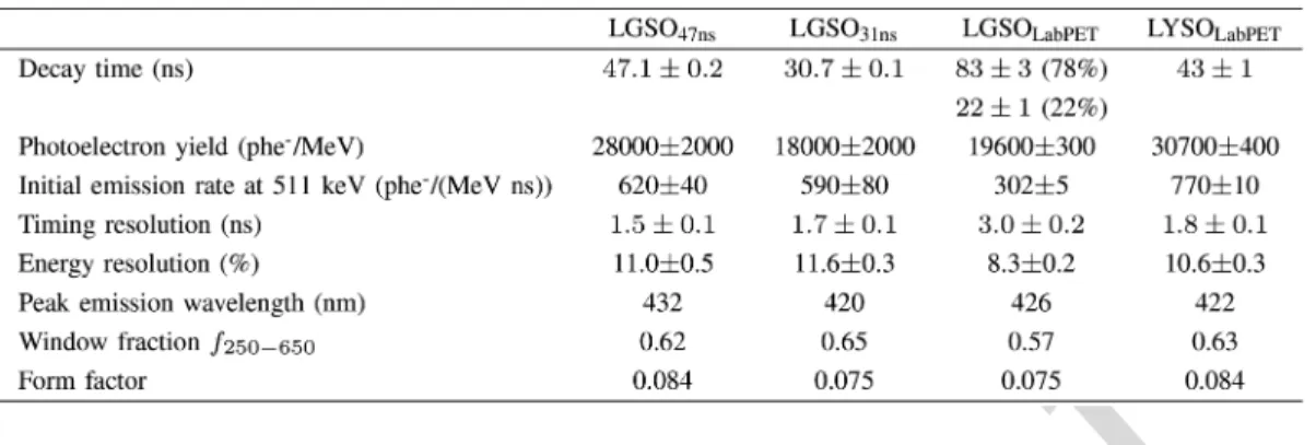
TABLE II
SPECTROSCOPICMEASUREMENTS ONINDIVIDUALCRYSTALS
measurements allow direct comparison with similar crystals in the phoswich modules.
Several physical characteristics were inspected, namely the decay time, the photoelectron yield, the energy and timing res-olutions, the peak emission wavelength and the crystal form factor (defined as the ratio of the detection surface area to the crystal volume). The decay time was measured by collecting 10 000 signals from the scintillators coupled to a fast PMT (RCA 4802-1) using a digital oscilloscope at 2 GSa/s (DSO6034 A, Agilent Technologies). The signals were averaged and the decay part of the curve was fitted using a single or double exponential regression. To evaluate the peak emission, UV-excited lumines-cence spectra were obtained using a spectrofluorometer (Hitachi F2000).
Four different scintillator types were investigated:
and from the current LabPET
module and and from the Type I module.
Four samples of each scintillator were measured. All exper-iments were performed with the crystals coated with Bicron BC-620 white paint, with the exception of the photoelectron yield measurements that have been performed with scintillators wrapped in layers of PTFE tape. All crystals were optically coupled to a mm UV-enhanced c7532 APD (Excelitas) operated at a gain of 120. The APD was connected to a custom low-noise charge-sensitive preamplifier (RCA 3.0) followed by an ORTEC 452 spectroscopy amplifier employed for all light yield and energy resolution measurements with a shaping time of s. The APD gain was calibrated by direct irradiation of the APD with 9 keV X-rays from a radiation source with the APD operated at low gain. The absolute light yield was then estimated by comparing to a reference pulse injected by a precision pulser at the input of the preamplifier through a calibrated 1 pF test capacitor. The intrinsic timing performance of the crystals coupled to an APD was assessed by coincidence against a fast PMT (RCA 4802-1) and plastic scintillator (NE102-A1-15c6 V) detector using a zero-cross time circuit connected to a time-amplitude converter (Ortec 467). For timing measurements, the signal from the APD-crystal detector was shaped with a fast filter amplifier (Ortec 474) having a 20 ns time constant and used to trigger a constant fraction discriminator with a 40% fraction and 4 ns ( ), 8 ns
( and ) or 20 ns ( ) delay.
All data were acquired at ambient temperature ( ) in a temperature controlled room.
III. RESULTS
A. Gamma Spectroscopy Measurements
Spectroscopic measurements for the individual crystals are reported in Table II and are in fair agreement with the scintillators physical characteristics (Table I). The results indicate excellent decay time uniformity between the four LGSO-90%Lu samples of each type. However, the tested samples did not possess a higher photoelectron
yield than the and , as reported
earlier [7], indicating that the crystal production may not be stable and that better results could be expected later on. The also presented a slightly lower photoelectron yield than the . The lower light yield of the
and could also be due to self-absorption, but the UV emission and excitation spectra did not show significant overlap. Comparison with current LabPET crystals suggests that modules made of LGSO-90%Lu will have a slightly de-graded energy resolution. The achieves a better energy resolution despite its lower light yield because there is likely less competition between Ce1 and Ce2 luminescence centers in this scintillator [18]. The and
timing resolution is equivalent to resolution ( ns) and significantly better than reso-lution ( ns). Emission wavelengths are very similar for all the scintillators. To enable the comparison of detection efficiency with a 250–650 keV energy window, the window fraction defined in Eq. (1) is also reported
photoelectric window keV keV window
(1)
B. Module Measurements
To characterize the new LabPET
modules as a replacement for the current LabPET module,
phoswich crystal identification is a prerequisite. At first glance,
the discrimination with the new phoswich combination, having a 16 ns decay time difference, appears more challenging than with the current module having a 25 ns difference. Decay time discrimination was performed using the same procedure as in the LabPET data processing chain [16].
IEEE Proof
Web Version
TABLE III MODULESPERFORMANCE
obtained with a LabPET8 scanner
Fig. 2. Detection efficiency ratio. The measurement was performed using a 662 keV source, 40 cm away from the detectors.
Fig. 3. Intrinsic spectra for current LabPET and Type I modules.
Table III reports the module performance as a comparison
between the Type I, Type II and
mod-ules. Contrary to what was observed in the spectroscopic mea-surements on individual crystals, the energy resolution is sim-ilar in all configurations, with a slight advantage with the Type II assembly. This could be explained by the different reflectors used in the two modules; the reflectivity of the silver foil used in the current LabPET module is 85%, while the reflectivity of the 3M ESR used in the Type I and II modules is about 98% above 400 nm. clearly shows better results than , regardless of the configuration, mostly due to its higher light yield. The expected relative light yield between the two
scin-tillators ( ) is , obtained from
Type I spectroscopic measurements. The relative light output
estimated from the photopeak positions in the module mea-surements yields for the Type I configuration and for the Type II configuration. The Type II configu-ration is slightly more balanced than Type I as it is closer to one and the two crystals should exhibit similar performance.
The average time resolution in coincidence was ns
for in both configurations and ns for
in Type I and ns in Type II. The time reso-lution of both assemblies is similar to the results obtained in
a LabPET8 scanner for ( ns) and better
than results obtained for ( ) [19]. The scintillator yields the best timing performance in both configurations as its higher light yield compensates for its slower decay time.
The ratio of the new module detection efficiency to the LabPET module detection efficiency was defined as
(2) where the singles rates from a 662 keV source are measured above an energy threshold. The ratios are found to be identical for Type I and Type II modules (the crystal composition is the
same), ranging from to with increasing
the energy threshold from 200 to 600 keV (see Fig. 2), which corresponds to a ratio of 1.3–1.5 in coincidence.
Fig. 3 shows the spectra obtained without an external radioac-tive source to evaluate the intrinsic radioactivity of the lutetium. The isotope (2.6% abundance, years half-life) decays by emission, followed by the emission of -ray(s) of 307 keV (94%), 202 keV (78%), and 88 keV (15%) [20]. Since the identification algorithm is less efficient at lower energy, the interaction crystal is poorly discriminated and it is preferable to compare the results at the phoswich level rather than the crystal level. Therefore, the two signals were added. From Fig. 3, the background count rate due to natural radioactivity is found to
be almost twice higher with the module
than with the standard LabPET module, due to the higher Lu content. This could be a problem for SPECT imaging using PET detectors [21], since this unwanted signal must be subtracted.
C. Sensitivity Improvement
A calculation was performed to compare the sensitivity of a PET system based on the new LGSO to the standard LabPET module. To estimate the sensitivity ratio, the first step was to evaluate the photoelectric detection efficiency of both modules using
IEEE Proof
Web Version
BERGERON et al.: IMPROVED LABPET DETECTORS USING (LGSO) SCINTILLATOR BLOCKS 5
TABLE IV
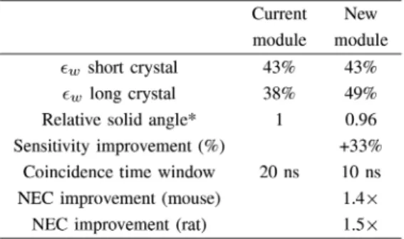
PREDICTEDIMPACT ONLABPET8 SCANNERPERFORMANCE(250–650KEV)
3M ESR reflector ( m) thicker than silver foil ( m)
where is the linear attenuation coefficient at 511 keV, is the photoelectric probability and the crystal length (mea-sured in the middle of the tapered crystals, respectively 11.9 and 13.3 mm for the shorter and longer components of the
phoswich [see Fig. 1(b)]. The sensitivity comparison is based
on a 250–650 keV energy window. This window was chosen to be compliant with LabPET standard acquisition mode and to overcome any possible light crosstalk mostly due to the cut-off frequency around 400 nm of the 3M ESR reflector [22]. Because this energy window was chosen rather than the photopeak only, a window fraction specific to each crystal, , must be added in Eq. (3) to adequately compare the sensitivity. The windowed detection efficiency is defined as (4) The ratio was assessed using the spectroscopic sam-ples and the results were reported in Table II, which completes the data needed to compare the modules sensitivities. Overall, the LGSO-90%Lu scintillators have more stopping power than and . Moreover, the photoelectric probability is higher, especially compared to the . The calculated windowed detection efficiencies, , are dis-played in Table IV. To evaluate the sensitivity ratio between the two modules, we used
(5) The theoretical sensitivity ratio is 1.29, using values from Table I and the window fraction obtained from spectroscopic measurements (Table II). Even with the slightly smaller packing fraction resulting from the slightly thicker reflector (by a 0.96 factor), the sensitivity would still be im-proved. Using the theoretical , it is possible to compare with the experimental ratio (Fig. 2). Since the ratio of detection efficiencies was for a 250 keV lower energy limit, the experimental sensitivity improvement will be
for a 250–650 keV window. The two values (1.29 and 1.36) are slightly different, mostly because of the imprecision coming from the ratio in the theoretical evaluation. The mean values of the two different estimations are for the singles ratio and for the coincidence rates ratio.
D. Noise Equivalent Count Rate Improvement
A standard width for the coincidence time window is about the FWHM time resolution to ensure the recovery of 98% of the coincidence events, assuming a Gaussian coincidence time distribution. Since the time resolution of both crystals in the new module is about half of the resolution, the coincidence time window can be reduced by up to a factor of 2 with the new detectors, leading to a reduction by a factor of 2 in the random rates. Considering that the LabPET peak noise equivalent count rate (NEC) occurs at a specific total count rates, the peak NEC activity for the new module would be slightly lower than for the current module, corresponding to the ratio of the detection efficiencies ( ). The NEC improvement can be calculated using
NEC improvement peak activity
peak activity (6) where
peak activity
(7) and where is the true rate, is the scatter rate and is the random rate of the LabPET modules. The improved detec-tion efficiency, along with the random rates reducdetec-tion, would result in an estimated NEC amelioration of for a mouse phantom and for a rat phantom. This was calculated using the LabPET8 scanner data [13].
IV. DISCUSSION
In the present work, the same electronic settings and firmware
as for and were employed without
any modifications. Signal processing could be adapted to the specific characteristics of the LGSO-90%Lu signal shapes.
As confirmed by all the measurements, the use of LGSO-90%Lu in the LabPET modules would be beneficial in many respects. Table IV summarizes the predicted impact on scanner performance using a 250–650 keV energy window, notably a increase in sensitivity and a NEC improve-ment of a factor for mouse imaging and
for rat imaging. The results obtained in this work confirm that the proposed all LGSO-based detector module can be manufactured with highly reproducible performance charac-teristics, as demonstrated by the small standard deviation in all measured data, and hence can be readily implemented in LabPET scanners. Whereas these scintillators performed well in a side-by-side phoswich like LabPET detector, they can be expected to perform even better in dual-layer assemblies for DOI detectors. The data reported in Table I suggest that the light yield could be improved if the crystal production was stabilized. If this was the case, this application would benefit from the good light yield of , given the unavoidable light loss at the phoswich crystal interface. This higher light yield would also open the way to better detection of lower energy signals in applications such as intercrystal recovery in high resolution PET [23], SPECT imaging using PET detectors [24] and counting CT imaging [25].
IEEE Proof
Web Version
V. CONCLUSIONThe new high lutetium LGSO scintillators with tunable decay time based on cerium concentration offer a great potential for simplifying detector assembly and improving PET imaging performance, by a simple replacement of the LabPET detector modules. These new crystals provide excellent timing resolu-tion while still supporting phoswich discriminaresolu-tion. They are expected to improve the LabPET scanner sensitivity and count rate performance, while significantly reducing random rates.
ACKNOWLEDGMENT
The authors would like to thank M. Toshinori Takeyama of Marubeni Specialty Chemicals Inc. (White Plains, NY) and Dr. H. Ishibashi of Hitachi Chemical Co., Ltd. (Ibaraki, Japan) for supplying the LGSO crystal samples.
REFERENCES
[1] C. Melcher, “Scintillation crystals for PET,” J. Nucl. Med., vol. 41, no. 6, pp. 1051–5, 2000.
[2] P. Lecoq and M. Korzhik, “New inorganic scintillation materials de-velopment for medical imaging,” IEEE Trans. Nucl. Sci., vol. 49, no. 4, pp. 1651–1654, Aug. 2002.
[3] P. Lecoq, E. Auffray, and S. Brunner et al., “Factors influencing time resolution of scintillators and ways to improve them,” IEEE Trans.
Nucl. Sci., vol. 57, no. 5, pp. 2411–2416, Oct. 2010.
[4] M. Kronberger, E. Auffray, and P. Lecoq, “Improving light extraction from heavy inorganic scintillators by photonic crystals,” IEEE Trans.
Nucl. Sci., vol. 57, no. 5, pp. 2475–2482, Oct. 2010.
[5] C. C. M. Kyba, J. Glodo, E. V. D. van Loef, and J. S. Karp, “Energy and timing response of six prototype scintillators for TOF-PET,” IEEE
Trans. Nucl. Sci., vol. 55, no. 3, pp. 1404–1408, Jun. 2008.
[6] M. Conti, L. Eriksson, H. Rothfuss, and C. Melcher, “Comparison of fast scintillators with TOF PET potential,” IEEE Trans. Nucl. Sci., vol. 56, no. 3, pp. 926–933, Jun. 2009.
[7] S. Shimizu, C. M. Pepin, M. Bergeron, and R. Lecomte, “Characteris-tics of (LGSO) for APD-based PET detector,”
IEEE Trans. Nucl. Sci., vol. 57, no. 1, pp. 55–62, Feb. 2010.
[8] S. Shimizu, C. M. Pepin, and R. Lecomte, “Assessment of (LGSO) scintillators with APD readout for PET/SPECT/CT detectors,” IEEE Trans. Nucl. Sci., vol. 57, no. 3, pp. 1512–1517, Jun. 2010.
[9] M. Schmand, L. Eriksson, and M. E. Casey et al., “Advantages using pulse shape discrimination to assign the depth of interaction informa-tion (DOI) from a multi layer phoswich detector,” IEEE Trans. Nucl.
Sci., vol. 46, no. 4, pp. 985–990, Aug. 1999.
[10] J. Seidel, J. Vaquero, S. Siegel, W. Gandler, and M. Green, “Depth identification accuracy of a three layer phoswich PET detector module,” IEEE Trans. Nucl. Sci., vol. 46, no. 3, pp. 485–490, Jun. 1999.
[11] A. Saoudi, C. Pepin, and F. Dion et al., “Investigation of depth-of-interaction by pulse shape discrimination in multicrystal detectors read out by avalanche photodiodes,” IEEE Trans. Nucl. Sci., vol. 46, no. 3, pp. 462–467, Jun. 1999.
[12] M. Streun, G. Brandenburg, and H. Larue et al., “Pulse shape discrim-ination of LSO and LuYAP scintillators for depth of interaction detec-tion in PET,” IEEE Trans. Nucl. Sci., vol. 50, no. 3, pp. 344–347, Jun. 2003.
[13] M. Bergeron, J. Cadorette, and J.-F. Beaudoin et al., “Performance evaluation of the LabPET APD-based digital PET scanner,” IEEE
Trans. Nucl. Sci., vol. 56, no. 1, pp. 10–16, Feb. 2009.
[14] C. M. Pepin, C. St-Pierre, and J. C. Forgues et al., “Physical character-ization of the LabPET LGSO and LYSO scintillators,” in 2007 Nucl.
Sci. Symp. Conf. Rec., 2007, vol. 3, pp. 2292–2295.
[15] G. Petrillo, R. J. McIntyre, R. Lecomte, G. Lamoureux, and D. Schmitt, “Scintillation detection with large-area reach-through avalanche pho-todiodes,” IEEE Trans. Nucl. Sci., vol. 31, no. 1, pp. 417–423, Feb. 1984.
[16] R. Fontaine, F. Belanger, and N. Viscogliosi et al., “The hardware and signal processing architecture of LabPET, a small animal APD-based digital PET scanner,” IEEE Trans. Nucl. Sci., vol. 56, no. 1, pp. 3–9, Feb. 2009.
[17] C. M. Pepin, H. Dautet, and M. Bergeron et al., “New UV-enhanced, ultra-low noise silicon avalanche photodiode for radiation detection and medical imaging,” in Proc. 2010 Nucl. Sci. Symp. Conf. Rec., 2010, pp. 1740–1746.
[18] A. Saoudi, C. M. Pepin, D. Houde, and R. Lecomte, “Scintillation light emission studies of LSO scintillators,” IEEE Trans. Nucl. Sci., vol. 46, no. 6, pp. 1925–1928, Dec. 1999.
[19] M. Bergeron, C. M. Pepin, and L. Arpin et al., “A handy time alignment probe for timing calibration of PET scanners,” Nucl. Instrum. Methods
Phys. Res. A, vol. 599, no. 1, pp. 113–117, 2009.
[20] A. L. Goertzen, J. Y. Suk, and C. J. Thompson, “Imaging of weak-source distributions in LSO-based small-animal PET scanners,”
J. Nucl. Med., vol. 48, no. 10, pp. 1692–8, 2007.
[21] R. Yao, T. Ma, and Y. Shao, “Lutetium oxyorthosilicate (LSO) in-trinsic activity correction and minimal detectable target activity study for SPECT imaging with a LSO-based animal PET scanner,” Phys.
Med. Biol., vol. 53, no. 16, pp. 4399–415, 2008.
[22] M. Janecek, “Reflectivity spectra for commonly used reflectors,” IEEE
Trans. Nucl. Sci., vol. 59, no. 3, pp. 490–497, Jun. 2012.
[23] J.-B. Michaud, M.-A. TÉtrault, and J.-F. Beaudoin et al., “Sensitivity increase through a neural network method for LOR recovery of ICS triple coincidences in high-resolution pixelated-detectors PET scan-ners,” IEEE Trans. Nucl. Sci., 2014, to be published.
[24] R. Yao, X. Deng, and J.-F. Beaudoin et al., “Initial evaluation of LabPET/SPECT dual modality animal imaging system,” IEEE Trans.
Nucl. Sci., vol. 60, no. 1, pp. 76–81, Feb. 2013.
[25] C. Thibaudeau, P. Bérard, and M.-A. Tétrault et al., “Toward truly combined PET/CT imaging using PET detectors and photon counting CT with iterative reconstruction implementing physical detector re-sponse,” Med. Phys., vol. 39, no. 9, pp. 5697–5707, 2012.
IEEE Proof
Print Version
IEEE TRANSACTIONS ON NUCLEAR SCIENCE 1
Improved LabPET Detectors Using
(LGSO) Scintillator Blocks
Mélanie Bergeron, Student Member, IEEE,
Catherine M. Pepin, Jules Cadorette, Francis Loignon-Houle, Réjean Fontaine, Senior Member, IEEE, and
Roger Lecomte, Senior Member, IEEE
Abstract—The scintillator is one of the key building blocks that
critically determine the physical performance of PET detectors. The quest for scintillation crystals with improved characteristics has been crucial in designing scanners with superior imaging performance. Recently, it was shown that the decay time con-stant of high lutetium content (LGSO) scintillators can be adjusted by varying the cerium concentra-tion from 0.025 mol% to 0.75 mol%, thus providing interesting characteristics for phoswich detectors. The high light output (90%–120% NaI) and the improved spectral match of these scintillators with avalanche photodiode (APD) readout promise superior energy and timing resolutions. Moreover, their improved mechanical properties, as compared to conventional LGSO ( ), make block array manufacturing readily feasible. To verify these assumptions, new phoswich block arrays made of LGSO-90%Lu with low and high mol% Ce con-centrations were fabricated and assembled into modules dedicated to the LabPET scanner. Typical crystal decay time constants were 31 ns and 47 ns, respectively. Phoswich crystal identification performed using a digital pulse shape discrimination algorithm yielded an average 8% error. At 511 keV, an energy resolution of 17–21% was obtained, while coincidence timing resolution between 4.6 ns and 5.2 ns was achieved. The characteristics of this new LGSO-based phoswich detector module are expected to improve the LabPET scanner performance. The higher stopping power would increase the detection efficiency. The better timing resolution would also allow the use of a narrower coincidence window, thus minimizing the random event rate. Altogether, these two improvements will significantly enhance the noise equivalent count rate performance of an all LGSO-based LabPET scanner.
Index Terms—Avalanche photodiodes, energy resolution,
LabPET, LGSO, positron emission tomography, scintillators, small-animal PET scanner, timing resolution.
Manuscript received September 15, 2014; revised November 21, 2014; ac-cepted December 28, 2014. This work was supported by Grants from the Natural Science and Engineering Research Council of Canada (NSERC), the Canadian Institutes of Health Research (CIHR), and Fonds de recherche du Québec
-Na-ture et technologies (FRQNT). The Sherbrooke Molecular Imaging Center is a
member of the FRSQ-funded Centre de Recherche du Centre hospitalier
uni-versitaire de Sherbrooke (CHUS).
M. Bergeron, C. M. Pepin, J. Cadorette, F. Loignon-Houle, and R. Lecomte are with the Sherbrooke Molecular Imaging Centre of CRCHUS and the Department of Nuclear Medicine and Radiobiology, Université de Sherbrooke, Sherbrooke, Québec, Canada (e-mail: [email protected]; [email protected]; [email protected]; [email protected]; [email protected]).
R. Fontaine is with the Department of Electrical Engineering and Computer Engineering, Université de Sherbrooke, Sherbrooke, Québec, Canada (e-mail: [email protected]).
Color versions of one or more of the figures in this paper are available online at http://ieeexplore.ieee.org.
I. INTRODUCTION
S
CINTILLATORS largely determine the basic performance of PET scanners. Expectedly, major efforts have been com-mitted to discover new scintillation materials, and also to im-prove characteristics of existing ones, such as stopping power, light output and emission decay time [1]–[4]. For instance, time-of-flight PET, which inherently needs an outstanding timing res-olution, prompted the search for new scintillators with higher light yield combined with faster decay time [5], [6]. In addi-tion, better timing and energy resolution for PET support the development of applications using lower energy radiation such as SPECT (140 keV) and CT ( keV).New high lutetium content
(LGSO-90%Lu) scintillators with high light output (90–120% NaI) and tunable fast decay times were recently introduced [7], [8]. The range of decay times from 31 to 47 ns, which can be adjusted by varying the Ce concentration from 0.025 to 0.75 mol%, makes them especially advantageous for creating phoswich arrange-ments, where the scintillating crystal can easily be identified with a simple pulse shape discrimination technique without sac-rificing the timing resolution [9]–[12]. Moreover, the similar emission and absorption properties of these new scintillators simplify the selection of the photodetector spectral response and avoid photon absorption in the other crystal of a phoswich as-sembly, since the two crystals are transparent to their own light. Direct replacement of the current LGSO-20%Lu
( ) and LYSO ( )
scintillators in the LabPET detector module would enhance the scanner performance [13]. Table I compares the previously reported crystal characteristics for LGSO-90%Lu along
with the two LabPET scintillators: and
. Some physical characteristics of LGSO-90%Lu and , such as density and effective Z, are very similar, but the higher light yield of LGSO-90%Lu when coupled to an avalanche photodiode (APD) readout makes it particularly attractive. Compared to the , the LGSO-90%Lu features a higher stopping power, a better light output and a faster decay time. Because of its higher lutetium content, the natural radioactivity of LGSO-90%Lu is however higher than , but still comparable to
, whose lutetium proportion is 95%.
Digital Object Identifier 10.1109/TNS.2015.2388757 0018-9499 © 2015 IEEE. Personal use is permitted, but republication/redistribution requires IEEE permission.
IEEE Proof
Print Version
TABLE I
LGSOANDLYSO PHYSICALCHARACTERISTICS
II. MATERIALS ANDMETHODS
A. Experimental Setup
Fast and slow LGSO-90% Lu samples, having nominal Ce concentrations of 0.025 mol% and 0.75 mol% respectively, were selected to allow the largest separation between decay times (31 ns and 47 ns) facilitating the crystal identification. and were then assembled in a phoswich arrangement as in LabPET modules [13]. In the current module, the phoswich pairs are assembled and
individually wrapped in unbounded silver foil before being placed four at a time into a hermetic Kovar package. In the new proposed configuration, the crystals are processed by Agile Technologies (Knoxville, TN, USA) starting from a larger piece of scintillator provided by Hitachi Chemical (Ibaraki, Japan), cut and mechanically polished to the required size, then bonded with 3M ESR reflector and assembled into a solid pixelated block with four adjacent phoswich pairs. Fig. 1(a) shows a schematic of the phoswich block design for one module along with its dimensions. The crystals are slightly smaller in the new module compared to the LabPET module, since the pitch was kept the same and the reflector thickness was changed ( m with 3M ESR compared to m with silver foil). In the current LabPET module, the was chosen as the longer crystal to compensate for its lower stopping power compared to the . Since the stopping power is the
same for and , it was decided to
eval-uate the two possible assemblies (Type I and Type II, Fig. 1(b)). For each configuration, the phoswich block was mounted with 4 reach-through APDs [15] of the same type as in the standard LabPET modules having a mm active area (Excelitas Technologies, Vaudreuil, QC, Canada), one for each phoswich pixel, and the assembly was hermetically enclosed in a standard LabPET package. To provide some assessment of the assembly procedure on detector performance, 20 such prototype modules (10 Type I and 10 Type II) were assembled.
Energy and timing resolution measurements were performed
at a stable temperature ( ) with a keV
radioactive source. This temperature is typical of the detector temperature in a LabPET scanner in normal operation. The APD bias was chosen to optimize timing resolution. Detection effi-ciency was assessed for the new Type I and Type II modules and compared to standard LabPET ones. For that measurement, a keV source was positioned 40 cm away from the detectors to insure that the incident radiation flux is the same for
Fig. 1. Schematic of the new LGSO phoswich block assembly with the optical coupling and 3M ESR reflector specifications (a) along with the two investigated module configurations: Type I and Type II (b).
all the detectors. The source was intentionally chosen in-stead of a positron emitter because its activity was high enough to limit the acquisition time and, thus, minimize temperature fluctuations during measurements in an open environment. The number of single counts above four energy thresholds (194, 324, 453 and 583 keV) were obtained using a 10-minute mea-surement and compared to the number of counts obtained with
current modules in an identical setup.
These four thresholds can be translated into a relation between the detection efficiency ratio and the lower energy threshold.
To evaluate the rate of natural radioactivity, a 2-h measure-ment was performed using the same setup, but without external radioactivity, and single counts were recorded. All mesurements were performed with standard LabPET digital data acquisition electronics [16].
B. Gamma Spectroscopy Measurements
To assess the intrinsic performance of the crystals, measure-ments were performed on individual pixels from the modules. Whereas results from these needle-like crystals with an
unfa-vorable form factor ( mm with a slant
plane) will be degraded relative to small cubic crystals ( mm ) commonly used in spectroscopic studies [17], these
IEEE Proof
Print Version
BERGERON et al.: IMPROVED LABPET DETECTORS USING (LGSO) SCINTILLATOR BLOCKS 3
TABLE II
SPECTROSCOPICMEASUREMENTS ONINDIVIDUALCRYSTALS
measurements allow direct comparison with similar crystals in the phoswich modules.
Several physical characteristics were inspected, namely the decay time, the photoelectron yield, the energy and timing res-olutions, the peak emission wavelength and the crystal form factor (defined as the ratio of the detection surface area to the crystal volume). The decay time was measured by collecting 10 000 signals from the scintillators coupled to a fast PMT (RCA 4802-1) using a digital oscilloscope at 2 GSa/s (DSO6034 A, Agilent Technologies). The signals were averaged and the decay part of the curve was fitted using a single or double exponential regression. To evaluate the peak emission, UV-excited lumines-cence spectra were obtained using a spectrofluorometer (Hitachi F2000).
Four different scintillator types were investigated:
and from the current LabPET
module and and from the Type I module.
Four samples of each scintillator were measured. All exper-iments were performed with the crystals coated with Bicron BC-620 white paint, with the exception of the photoelectron yield measurements that have been performed with scintillators wrapped in layers of PTFE tape. All crystals were optically coupled to a mm UV-enhanced c7532 APD (Excelitas) operated at a gain of 120. The APD was connected to a custom low-noise charge-sensitive preamplifier (RCA 3.0) followed by an ORTEC 452 spectroscopy amplifier employed for all light yield and energy resolution measurements with a shaping time of s. The APD gain was calibrated by direct irradiation of the APD with 9 keV X-rays from a radiation source with the APD operated at low gain. The absolute light yield was then estimated by comparing to a reference pulse injected by a precision pulser at the input of the preamplifier through a calibrated 1 pF test capacitor. The intrinsic timing performance of the crystals coupled to an APD was assessed by coincidence against a fast PMT (RCA 4802-1) and plastic scintillator (NE102-A1-15c6 V) detector using a zero-cross time circuit connected to a time-amplitude converter (Ortec 467). For timing measurements, the signal from the APD-crystal detector was shaped with a fast filter amplifier (Ortec 474) having a 20 ns time constant and used to trigger a constant fraction discriminator with a 40% fraction and 4 ns ( ), 8 ns
( and ) or 20 ns ( ) delay.
All data were acquired at ambient temperature ( ) in a temperature controlled room.
III. RESULTS
A. Gamma Spectroscopy Measurements
Spectroscopic measurements for the individual crystals are reported in Table II and are in fair agreement with the scintillators physical characteristics (Table I). The results indicate excellent decay time uniformity between the four LGSO-90%Lu samples of each type. However, the tested samples did not possess a higher photoelectron
yield than the and , as reported
earlier [7], indicating that the crystal production may not be stable and that better results could be expected later on. The also presented a slightly lower photoelectron yield than the . The lower light yield of the
and could also be due to self-absorption, but the UV emission and excitation spectra did not show significant overlap. Comparison with current LabPET crystals suggests that modules made of LGSO-90%Lu will have a slightly de-graded energy resolution. The achieves a better energy resolution despite its lower light yield because there is likely less competition between Ce1 and Ce2 luminescence centers in this scintillator [18]. The and
timing resolution is equivalent to resolution ( ns) and significantly better than reso-lution ( ns). Emission wavelengths are very similar for all the scintillators. To enable the comparison of detection efficiency with a 250–650 keV energy window, the window fraction defined in Eq. (1) is also reported
photoelectric window keV keV window
(1)
B. Module Measurements
To characterize the new LabPET
modules as a replacement for the current LabPET module,
phoswich crystal identification is a prerequisite. At first glance,
the discrimination with the new phoswich combination, having a 16 ns decay time difference, appears more challenging than with the current module having a 25 ns difference. Decay time discrimination was performed using the same procedure as in the LabPET data processing chain [16].
IEEE Proof
Print Version
TABLE III MODULESPERFORMANCE
obtained with a LabPET8 scanner
Fig. 2. Detection efficiency ratio. The measurement was performed using a 662 keV source, 40 cm away from the detectors.
Fig. 3. Intrinsic spectra for current LabPET and Type I modules.
Table III reports the module performance as a comparison
between the Type I, Type II and
mod-ules. Contrary to what was observed in the spectroscopic mea-surements on individual crystals, the energy resolution is sim-ilar in all configurations, with a slight advantage with the Type II assembly. This could be explained by the different reflectors used in the two modules; the reflectivity of the silver foil used in the current LabPET module is 85%, while the reflectivity of the 3M ESR used in the Type I and II modules is about 98% above 400 nm. clearly shows better results than , regardless of the configuration, mostly due to its higher light yield. The expected relative light yield between the two
scin-tillators ( ) is , obtained from
Type I spectroscopic measurements. The relative light output
estimated from the photopeak positions in the module mea-surements yields for the Type I configuration and for the Type II configuration. The Type II configu-ration is slightly more balanced than Type I as it is closer to one and the two crystals should exhibit similar performance.
The average time resolution in coincidence was ns
for in both configurations and ns for
in Type I and ns in Type II. The time reso-lution of both assemblies is similar to the results obtained in
a LabPET8 scanner for ( ns) and better
than results obtained for ( ) [19]. The scintillator yields the best timing performance in both configurations as its higher light yield compensates for its slower decay time.
The ratio of the new module detection efficiency to the LabPET module detection efficiency was defined as
(2) where the singles rates from a 662 keV source are measured above an energy threshold. The ratios are found to be identical for Type I and Type II modules (the crystal composition is the
same), ranging from to with increasing
the energy threshold from 200 to 600 keV (see Fig. 2), which corresponds to a ratio of 1.3–1.5 in coincidence.
Fig. 3 shows the spectra obtained without an external radioac-tive source to evaluate the intrinsic radioactivity of the lutetium. The isotope (2.6% abundance, years half-life) decays by emission, followed by the emission of -ray(s) of 307 keV (94%), 202 keV (78%), and 88 keV (15%) [20]. Since the identification algorithm is less efficient at lower energy, the interaction crystal is poorly discriminated and it is preferable to compare the results at the phoswich level rather than the crystal level. Therefore, the two signals were added. From Fig. 3, the background count rate due to natural radioactivity is found to
be almost twice higher with the module
than with the standard LabPET module, due to the higher Lu content. This could be a problem for SPECT imaging using PET detectors [21], since this unwanted signal must be subtracted.
C. Sensitivity Improvement
A calculation was performed to compare the sensitivity of a PET system based on the new LGSO to the standard LabPET module. To estimate the sensitivity ratio, the first step was to evaluate the photoelectric detection efficiency of both modules using
IEEE Proof
Print Version
BERGERON et al.: IMPROVED LABPET DETECTORS USING (LGSO) SCINTILLATOR BLOCKS 5
TABLE IV
PREDICTEDIMPACT ONLABPET8 SCANNERPERFORMANCE(250–650KEV)
3M ESR reflector ( m) thicker than silver foil ( m)
where is the linear attenuation coefficient at 511 keV, is the photoelectric probability and the crystal length (mea-sured in the middle of the tapered crystals, respectively 11.9 and 13.3 mm for the shorter and longer components of the
phoswich [see Fig. 1(b)]. The sensitivity comparison is based
on a 250–650 keV energy window. This window was chosen to be compliant with LabPET standard acquisition mode and to overcome any possible light crosstalk mostly due to the cut-off frequency around 400 nm of the 3M ESR reflector [22]. Because this energy window was chosen rather than the photopeak only, a window fraction specific to each crystal, , must be added in Eq. (3) to adequately compare the sensitivity. The windowed detection efficiency is defined as (4) The ratio was assessed using the spectroscopic sam-ples and the results were reported in Table II, which completes the data needed to compare the modules sensitivities. Overall, the LGSO-90%Lu scintillators have more stopping power than and . Moreover, the photoelectric probability is higher, especially compared to the . The calculated windowed detection efficiencies, , are dis-played in Table IV. To evaluate the sensitivity ratio between the two modules, we used
(5) The theoretical sensitivity ratio is 1.29, using values from Table I and the window fraction obtained from spectroscopic measurements (Table II). Even with the slightly smaller packing fraction resulting from the slightly thicker reflector (by a 0.96 factor), the sensitivity would still be im-proved. Using the theoretical , it is possible to compare with the experimental ratio (Fig. 2). Since the ratio of detection efficiencies was for a 250 keV lower energy limit, the experimental sensitivity improvement will be
for a 250–650 keV window. The two values (1.29 and 1.36) are slightly different, mostly because of the imprecision coming from the ratio in the theoretical evaluation. The mean values of the two different estimations are for the singles ratio and for the coincidence rates ratio.
D. Noise Equivalent Count Rate Improvement
A standard width for the coincidence time window is about the FWHM time resolution to ensure the recovery of 98% of the coincidence events, assuming a Gaussian coincidence time distribution. Since the time resolution of both crystals in the new module is about half of the resolution, the coincidence time window can be reduced by up to a factor of 2 with the new detectors, leading to a reduction by a factor of 2 in the random rates. Considering that the LabPET peak noise equivalent count rate (NEC) occurs at a specific total count rates, the peak NEC activity for the new module would be slightly lower than for the current module, corresponding to the ratio of the detection efficiencies ( ). The NEC improvement can be calculated using
NEC improvement peak activity
peak activity (6) where
peak activity
(7) and where is the true rate, is the scatter rate and is the random rate of the LabPET modules. The improved detec-tion efficiency, along with the random rates reducdetec-tion, would result in an estimated NEC amelioration of for a mouse phantom and for a rat phantom. This was calculated using the LabPET8 scanner data [13].
IV. DISCUSSION
In the present work, the same electronic settings and firmware
as for and were employed without
any modifications. Signal processing could be adapted to the specific characteristics of the LGSO-90%Lu signal shapes.
As confirmed by all the measurements, the use of LGSO-90%Lu in the LabPET modules would be beneficial in many respects. Table IV summarizes the predicted impact on scanner performance using a 250–650 keV energy window, notably a increase in sensitivity and a NEC improve-ment of a factor for mouse imaging and
for rat imaging. The results obtained in this work confirm that the proposed all LGSO-based detector module can be manufactured with highly reproducible performance charac-teristics, as demonstrated by the small standard deviation in all measured data, and hence can be readily implemented in LabPET scanners. Whereas these scintillators performed well in a side-by-side phoswich like LabPET detector, they can be expected to perform even better in dual-layer assemblies for DOI detectors. The data reported in Table I suggest that the light yield could be improved if the crystal production was stabilized. If this was the case, this application would benefit from the good light yield of , given the unavoidable light loss at the phoswich crystal interface. This higher light yield would also open the way to better detection of lower energy signals in applications such as intercrystal recovery in high resolution PET [23], SPECT imaging using PET detectors [24] and counting CT imaging [25].
IEEE Proof
Print Version
V. CONCLUSIONThe new high lutetium LGSO scintillators with tunable decay time based on cerium concentration offer a great potential for simplifying detector assembly and improving PET imaging performance, by a simple replacement of the LabPET detector modules. These new crystals provide excellent timing resolu-tion while still supporting phoswich discriminaresolu-tion. They are expected to improve the LabPET scanner sensitivity and count rate performance, while significantly reducing random rates.
ACKNOWLEDGMENT
The authors would like to thank M. Toshinori Takeyama of Marubeni Specialty Chemicals Inc. (White Plains, NY) and Dr. H. Ishibashi of Hitachi Chemical Co., Ltd. (Ibaraki, Japan) for supplying the LGSO crystal samples.
REFERENCES
[1] C. Melcher, “Scintillation crystals for PET,” J. Nucl. Med., vol. 41, no. 6, pp. 1051–5, 2000.
[2] P. Lecoq and M. Korzhik, “New inorganic scintillation materials de-velopment for medical imaging,” IEEE Trans. Nucl. Sci., vol. 49, no. 4, pp. 1651–1654, Aug. 2002.
[3] P. Lecoq, E. Auffray, and S. Brunner et al., “Factors influencing time resolution of scintillators and ways to improve them,” IEEE Trans.
Nucl. Sci., vol. 57, no. 5, pp. 2411–2416, Oct. 2010.
[4] M. Kronberger, E. Auffray, and P. Lecoq, “Improving light extraction from heavy inorganic scintillators by photonic crystals,” IEEE Trans.
Nucl. Sci., vol. 57, no. 5, pp. 2475–2482, Oct. 2010.
[5] C. C. M. Kyba, J. Glodo, E. V. D. van Loef, and J. S. Karp, “Energy and timing response of six prototype scintillators for TOF-PET,” IEEE
Trans. Nucl. Sci., vol. 55, no. 3, pp. 1404–1408, Jun. 2008.
[6] M. Conti, L. Eriksson, H. Rothfuss, and C. Melcher, “Comparison of fast scintillators with TOF PET potential,” IEEE Trans. Nucl. Sci., vol. 56, no. 3, pp. 926–933, Jun. 2009.
[7] S. Shimizu, C. M. Pepin, M. Bergeron, and R. Lecomte, “Characteris-tics of (LGSO) for APD-based PET detector,”
IEEE Trans. Nucl. Sci., vol. 57, no. 1, pp. 55–62, Feb. 2010.
[8] S. Shimizu, C. M. Pepin, and R. Lecomte, “Assessment of (LGSO) scintillators with APD readout for PET/SPECT/CT detectors,” IEEE Trans. Nucl. Sci., vol. 57, no. 3, pp. 1512–1517, Jun. 2010.
[9] M. Schmand, L. Eriksson, and M. E. Casey et al., “Advantages using pulse shape discrimination to assign the depth of interaction informa-tion (DOI) from a multi layer phoswich detector,” IEEE Trans. Nucl.
Sci., vol. 46, no. 4, pp. 985–990, Aug. 1999.
[10] J. Seidel, J. Vaquero, S. Siegel, W. Gandler, and M. Green, “Depth identification accuracy of a three layer phoswich PET detector module,” IEEE Trans. Nucl. Sci., vol. 46, no. 3, pp. 485–490, Jun. 1999.
[11] A. Saoudi, C. Pepin, and F. Dion et al., “Investigation of depth-of-interaction by pulse shape discrimination in multicrystal detectors read out by avalanche photodiodes,” IEEE Trans. Nucl. Sci., vol. 46, no. 3, pp. 462–467, Jun. 1999.
[12] M. Streun, G. Brandenburg, and H. Larue et al., “Pulse shape discrim-ination of LSO and LuYAP scintillators for depth of interaction detec-tion in PET,” IEEE Trans. Nucl. Sci., vol. 50, no. 3, pp. 344–347, Jun. 2003.
[13] M. Bergeron, J. Cadorette, and J.-F. Beaudoin et al., “Performance evaluation of the LabPET APD-based digital PET scanner,” IEEE
Trans. Nucl. Sci., vol. 56, no. 1, pp. 10–16, Feb. 2009.
[14] C. M. Pepin, C. St-Pierre, and J. C. Forgues et al., “Physical character-ization of the LabPET LGSO and LYSO scintillators,” in 2007 Nucl.
Sci. Symp. Conf. Rec., 2007, vol. 3, pp. 2292–2295.
[15] G. Petrillo, R. J. McIntyre, R. Lecomte, G. Lamoureux, and D. Schmitt, “Scintillation detection with large-area reach-through avalanche pho-todiodes,” IEEE Trans. Nucl. Sci., vol. 31, no. 1, pp. 417–423, Feb. 1984.
[16] R. Fontaine, F. Belanger, and N. Viscogliosi et al., “The hardware and signal processing architecture of LabPET, a small animal APD-based digital PET scanner,” IEEE Trans. Nucl. Sci., vol. 56, no. 1, pp. 3–9, Feb. 2009.
[17] C. M. Pepin, H. Dautet, and M. Bergeron et al., “New UV-enhanced, ultra-low noise silicon avalanche photodiode for radiation detection and medical imaging,” in Proc. 2010 Nucl. Sci. Symp. Conf. Rec., 2010, pp. 1740–1746.
[18] A. Saoudi, C. M. Pepin, D. Houde, and R. Lecomte, “Scintillation light emission studies of LSO scintillators,” IEEE Trans. Nucl. Sci., vol. 46, no. 6, pp. 1925–1928, Dec. 1999.
[19] M. Bergeron, C. M. Pepin, and L. Arpin et al., “A handy time alignment probe for timing calibration of PET scanners,” Nucl. Instrum. Methods
Phys. Res. A, vol. 599, no. 1, pp. 113–117, 2009.
[20] A. L. Goertzen, J. Y. Suk, and C. J. Thompson, “Imaging of weak-source distributions in LSO-based small-animal PET scanners,”
J. Nucl. Med., vol. 48, no. 10, pp. 1692–8, 2007.
[21] R. Yao, T. Ma, and Y. Shao, “Lutetium oxyorthosilicate (LSO) in-trinsic activity correction and minimal detectable target activity study for SPECT imaging with a LSO-based animal PET scanner,” Phys.
Med. Biol., vol. 53, no. 16, pp. 4399–415, 2008.
[22] M. Janecek, “Reflectivity spectra for commonly used reflectors,” IEEE
Trans. Nucl. Sci., vol. 59, no. 3, pp. 490–497, Jun. 2012.
[23] J.-B. Michaud, M.-A. TÉtrault, and J.-F. Beaudoin et al., “Sensitivity increase through a neural network method for LOR recovery of ICS triple coincidences in high-resolution pixelated-detectors PET scan-ners,” IEEE Trans. Nucl. Sci., 2014, to be published.
[24] R. Yao, X. Deng, and J.-F. Beaudoin et al., “Initial evaluation of LabPET/SPECT dual modality animal imaging system,” IEEE Trans.
Nucl. Sci., vol. 60, no. 1, pp. 76–81, Feb. 2013.
[25] C. Thibaudeau, P. Bérard, and M.-A. Tétrault et al., “Toward truly combined PET/CT imaging using PET detectors and photon counting CT with iterative reconstruction implementing physical detector re-sponse,” Med. Phys., vol. 39, no. 9, pp. 5697–5707, 2012.