This is an author-deposited version published in:
http://oatao.univ-toulouse.fr/
Eprints ID: 8783
To link to this article: DOI: 10.1016/j.carbon.2012.10.030
URL:
http://dx.doi.org/10.1016/j.carbon.2012.10.030
To cite this version:
Kasperski, Anne and Weibel, Alicia and Estournès,
Claude and Laurent, Christophe and Peigney, Alain
Preparation-microstructure-property
relationships
in
double-walled
carbon
nanotubes/alumina composites. (2013) Carbon, vol. 53 . pp. 62-72. ISSN
0008-6223
!
O
pen
A
rchive
T
oulouse
A
rchive
O
uverte (
OATAO
)
OATAO is an open access repository that collects the work of Toulouse researchers and
makes it freely available over the web where possible.
Any correspondence concerning this service should be sent to the repository
administrator:
[email protected]
!
Preparation-microstructure-property relationships in
double-walled carbon nanotubes/alumina composites
A. Kasperski, A. Weibel, C. Estourne`s, Ch. Laurent, A. Peigney
*Universite´ de Toulouse, Institut Carnot CIRIMAT, UMR CNRS-UPS-INP 5085, Universite´ Paul-Sabatier, 118 route de Narbonne, 31062 Toulouse cedex 9, France
A B S T R A C T
Double-walled carbon nanotube/alumina composite powders with low carbon contents (2– 3 wt.%) are prepared using three different methods and densified by spark plasma sinter-ing. The mechanical properties and electrical conductivity are investigated and correlated with the microstructure of the dense materials. Samples prepared by in situ synthesis of carbon nanotubes (CNTs) in impregnated submicronic alumina are highly homogeneous and present the higher electrical conductivity (2.2–3.5 S cmÿ1) but carbon films at grain
boundaries induce a poor cohesion of the materials. Composites prepared by mixing using moderate sonication of as-prepared double-walled CNTs and lyophilisation, with little damage to the CNTs, have a fracture strength higher (+30%) and a fracture toughness sim-ilar (5.6 vs 5.4 MPa m1/2) to alumina with a similar submicronic grain size. This is
corre-lated with crack-bridging by CNTs on a large scale, despite a lack of homogeneity of the CNT distribution.
1.
Introduction
A new class of ceramic matrix composites obtained by the incorporation of carbon nanotubes (CNTs) in oxides, carbides or nitrides is studied from about fifteen years. The most recent reviews on this topic have been written by Cho et al.[1]and Zapatas-Solvas et al.[2]. CNTs are known for their huge aspect ratio and their amazing mechanical, electrical and thermal properties. Consequently, the preparation and properties of these new composites have been explored in the aim to obtain higher or particular effects leading to improved properties, in comparison with those brought by the incorporation of micro-metric ceramic fibers or of brittle or ductile particles having a size either micrometric or nanometric. Particularly, the prepa-ration of tougher ceramics is intensively researched. The prep-aration of the composite powder is a critical step because all methods, such as conventional powder milling, colloidal mixing, sol–gel and in situ growth of CNTs by catalytic
chemical vapor decomposition (CCVD) do not lead to the same degree of dispersion of the CNTs[1,2]. The in situ growth of CNTs by CCVD gives a very homogeneous dispersion but it is necessary to very well disperse catalytic metal nanoparticles in the starting catalytic material. This is fully achieved when the metal nanoparticles are generated in situ from the reduc-tion of an oxide solid solureduc-tion[3]. The second critical step is to achieve the consolidation and densification of the materials while avoiding or limiting the damage to the CNTs. Because it requires lower temperature and shorter time than hot-pressing (HP), spark plasma sintering (SPS) is preferred, leading to near full densification if the CNT content is not too high[1,2]. It has been demonstrated that, owing to the CNT percolation at a very low content (<1 wt.%), ceramic matrix composites become electrically conductive when the corresponding ceramic matrix is insulating, while keeping their mechanical properties[4,5]. For a given type of CNT (differing mostly by the number of walls) and a given carbon content, and in same
http://dx.doi.org/10.1016/j.carbon.2012.10.030 * Corresponding author: Fax: +33 561556163.
matrix, the value of the electrical conductivity accounts for the homogeneity of their dispersion. The possibility to obtain a huge increase in fracture toughness remains uncertain be-cause the higher reported increases in toughness are derived from measurements obtained by indentation (ID), a method whose validity is contested by several authors, both in the case of measurements made on CNT/ceramic composites[6]and on ceramics[7]. So, if we consider only the fracture toughness measured by the single-edge notched beam (SENB) method or similar methods, only a few authors reported a significant in-crease in comparison of their own ceramic, most by using the alumina matrix and preferentially multi-walled carbon nano-tubes (MWCNTs)[1,2]. But the highest reported value (about 7 MPa m1/2)[8]is lower than that obtained by a fine control of the
microstructure in pure alumina[9]. Moreover, it was shown that the use of CNTs having a high-load carrying capacity, in order to avoid the so-called ‘‘sword-in-sheath’’ fracture mode, may lead to composites with a higher fracture toughness[10]. For DWCNTs, Bichoutskaia et al.[11]reported a shear strength for the relative sliding of walls along the axis between 4 and 215 MPa depending of the structure of the tubes, which is much more than the values (<0.04 MPa) reported by Kis et al. [12] for MWCNTs. Thus, double-walled carbon nanotubes (DWCNTs) may be more desirable than MWCNTs for the de-sign of tougher ceramic-matrix composites. Most alumina composites containing single-wall carbon nanotubes (SWCNTs) and DWCNTs present disappointing mechanical properties[13,14]. However, Zapata-Solvas et al.[15] demon-strated that SWCNT/Al2O3composites can be two orders of
magnitude more creep-resistant compared to a pure alumina specimen of about same grain size (0.5 lm). Interestingly, some results obtained with other ceramic matrices seem to be more promising. Mukhopadhay et al.[16]and Ye et al.[17] obtained between 2- and 3-fold increases in fracture tough-ness in glasses reinforced with MWCNTs. Peigney et al.[18] re-ported an unambiguous increase in both toughness (up to 6.7 MPa m1/2) and microhardness (12.2 GPa) for
DWCNT-nano-structured magnesia composites prepared by in situ synthesis and SPS and evidenced the mechanisms of crack-bridging on an unprecedented scale, crack-deflection and DWCNT pullout. It was argued that these very high values for a MgO matrix composite arise because the unique microstructure (low con-tent of long DWCNTs, nanometric matrix grains and grain boundary cohesion) provides the appropriate scale of the rein-forcement to make the material tough[18]. It was also noted that a too high content of DWCNTs weakens the material [18]. Indeed, when using DWCNTs as opposed to MWCNTs, adding a carbon content in the composites similar to that typ-ically added for MWCNTs (5–10 vol.%) would result in a far higher number of DWCNTs because a DWCNT weights much less than a MWCNT of the same length, all the more so upon the increase of the number of walls [19]. Therefore, when using mainly DWCNTs, it is preferable to add a lower carbon content in the composites, compared to that usually added using MWCNTs. The aim of the present work is to prepare alu-mina matrix composites with a microstructure similar to the toughened DWCNT/MgO samples[18]. Two types of methods are used for the preparation of the composite powders: in the first one, DWCNTs are synthesized in situ in a submicronic sized alumina powder; in the second one, pre-existing
high-quality DWCNTs are mixed with the alumina powder without any milling process. The powders are densified by SPS. The mechanical properties and electrical conductivity are investigated and correlated with the microstructure of the dense materials, with a particular attention brought to the degree of damaging of CNTs and matrix grain size and their influence on the reinforcement mechanisms.
2.
Experimental methods
2.1. Powder preparation
2.1.1. In-situ route
Two composite powders (C1 and C2) were prepared by in situ synthesis of CNTs via the CCVD route. A commercial alumina powder with an average grain size of 140 nm[20]and a 99.99% purity (TAIMEI Chemicals Co., Ltd.) was impregnated with Fe(NO3)2Æ9H2O and (NH4)6Mo7O24Æ4H2O dissolved in de-ionized
water. The quantity of water was optimized to homoge-neously wet the powder sample without leading to any super-natant. Afterwards the powder was dried overnight at 60 °C and calcinated at 500 °C for one hour in air. Two different cat-alytic materials were prepared. The molar ratios Fe:Mo:Al were 4:1:800 and 5:1:500 in the oxide powders (corresponding to the C1 and C2 composite powders respectively). The so-obtained catalytic materials were then reduced in a H2–CH4
mixture (20 mol.% CH4, heating and cooling rates 5 °C minÿ1,
maximum temperature 1050 °C, no dwell) in order to form the CNTs.
2.1.2. Mixing route
Two composite powders (C3 and C4) were prepared by a mix-ing route without any millmix-ing step. DWCNTs were synthe-sized by the CCVD route as reported earlier [21]. The Mg0.99(Co0.75Mo0.25)0.010O catalytic material was submitted to
a CCVD treatment (H2–CH4, 18 mol.% CH4, heating and cooling
rates 5 °C minÿ1, maximum temperature 1000 °C, no dwell),
producing a CNT–Co/Mo–MgO composite powder. This pow-der was soaked in a 37% HCl aqueous solution in orpow-der to dis-solve MgO and most of the cobalt and molybdenum species, without damaging the CNTs[22]. The so-obtained suspension was filtered, washed with de-ionized water until neutrality, and kept wet (no any drying step) in order to facilitate a fur-ther dispersion. The CNTs in the sample are mostly DWCNTs (80%), SWCNTs (15%) and CNTs with three walls (5%), with the outer diameter in the range 1–3 nm and the inner diameter in the range 0.5–2.5 nm[21]. These CNTs were used to prepare CNT–alumina powders, with a carbon content of 2 wt.% by two different methods. The C3 composite powder was pre-pared by the following mixing route: a high-power tip sonica-tion (Model Vibra Cell 75042, 20 Hz, 500 W) with a glass horn adaptor equipped with a water cooling system was used to disperse successively the suspensions of CNTs and alumina. This system avoids direct contact between the CNTs and the probe, which limits the sonication energy and thus the CNT damage. Firstly, the alumina powder (the same one than that used for C1 and C2 preparation) was dispersed in an aqueous solution at pH 12 by a succession of alternated sonication and mechanical stirring (twice 15 min, 15 min and 1 h, respectively). During the last mechanical stirring of
alumina, the wet as-prepared DWCNTs were dispersed in an aqueous solution (pH 12) and sonicated for 30 min. Then the two suspensions were mixed and sonicated for 1.5 h. The vessel containing the CNT-alumina suspension was im-mersed in liquid N2until the mixture was frozen and then it
was freeze-dried (Christ Alpha 2–4 LD, Bioblock Scientific) at ÿ40 °C in a primary vacuum (12 Pa) until there is no ice any-more. The C4 composite powder was prepared by the follow-ing mixfollow-ing route: the wet as-prepared DWCNTs were functionalized by immersion in a mixture (3/1) of concen-trated sulphuric acid and nitric acid for 24 h at room temper-ature[23]. Then, the mixture was neutralized with ammonia, washed with de-ionized water and filtered while keeping the CNTs wet[23]. The functionalized DWCNTs were dispersed in water for 15 min in direct contact with the probe. Meanwhile a suspension of alumina in an aqueous solution (pH 12) was sonicated for 15 min, and then mechanically stirred for 1 h. Afterwards the as-prepared CNT suspension was poured into the alumina suspension and mixed by probe sonication and mechanical stirring for 1 h. The so-obtained composite sus-pension was then frozen by immersing it in liquid N2 and
lyophilized as above. The preparation conditions of all com-posite powders are reported inTable 1(results and discussion section).
2.2. Spark-plasma-sintering
Two pellets of each composite (C1–C4) were been prepared by the SPS treatment (Dr. Sinter 2080, SPS Syntex Inc., Japan). Firstly the powders were compacted in a stainless steel die (inner diameter 20 mm) under a uniaxial pressure of 200 MPa. Then, the green samples were loaded into a 20 mm inner diameter graphite die. A sheet of graphitic paper was placed between the punch and the powder as well as between the die and the powder for easy removal. The treatment was conducted in a vacuum (residual cell pressure <3 Pa). A pulse configuration of 12 pulses (one pulse duration 3.3 ms) fol-lowed by 2 periods (6.6 ms) of zero current was used. Heating rates of 150 °C/min and 100 °C/min were used from room temperature to 650 °C and from 650 to 1350 °C, respectively, where a 6 min dwell was applied, and then the samples were cooled down with a rate of 100 °C/min. An optical pyrometer, focused on a little hole at the surface of the die, was used to measure the temperature. A uniaxial charge (corresponding to 150 MPa) was applied during the dwell and gradually re-leased during cooling. For the sake of comparison, an alumina sample (A1) was prepared in the same SPS conditions using
the as-received commercial alumina powder. Another alu-mina sample (A2) was also prepared in different SPS condi-tions optimized to limit the grain growth: dwell temperature of 1150 °C, dwell time of 5 min, uniaxial pressure of 100 MPa. All sintered specimen were pellets 20 mm in diame-ter with a thickness about 2.5 mm and were polished with a diamond paste up to 1 lm.
2.3. Microstructure characterization
The carbon content in the in situ synthesized composite pow-ders was measured by flash combustion with a relative accu-racy of 2%. The C2 powder was observed by high resolution transmission electron microscopy (HRTEM, JEOL JEM 2100F operated at 120 kV). The in situ synthesized composite pow-ders and all the pellet fracture surfaces were observed by field-emission-gun scanning electron microscopy (FESEM, JEOL JSM 6700F). The average grain size of the dense material was determined from SEM images by using the mean linear intercept method. The Raman spectra of the powders and of the polished surfaces of sintered materials were obtained with a Jobin–Yvon LabRAM HR 800 spectrometer (laser excita-tion at 632.82 nm). Between three and six Raman spectra were averaged for each sample. The density of the pellets was mea-sured by the Archimedes method. The relative densities (q ± 0.6%) were calculated using 1.80 for DWCNTs and suppos-ing that iron and molybdenum are under the form of Fe3C and
Mo2C respectively.
2.4. Electrical and mechanical testing
The electrical conductivity was measured at room tempera-ture with direct currents on parallelepipedic specimens (1.8 · 1.8 · 1.5 mm3), parallel to their length, i.e. perpendicular
to the pressing axis. The current densities used were lower than 160 mA/cm2 (Keithley 2400). The indentation tests
(300 g for 10 s in air at room temperature) were performed on the polished surface of the specimens by loading with a Vickers indenter (Shimadzu HMV 2000). The corresponding diagonals of the indentation were measured using an optical microscope attached to the indenter. The calculated micro-hardness values are the average of ten measurements. The transverse fracture strength (rf) was measured by the
three-point bending method on parallelepiped specimens about 1.8 · 1.8 · 18 mm3. The fracture toughness (K
Ic) was measured
by the SENB method on similar specimens notched with a diamond blade 0.3 mm in width and calculated using the
cal-Table 1 – For each composite C1 to C4, CNT types, carbon content, composite powder preparation method and ID/IG(%) ratio
between D and G bands of the Raman spectra, at each step of the composite preparation. The ratios have been calculated using between 3 and 6 spectra, depending of the samples, and the minimum and maximum values (min–max) are also reported.
Label CNT type Powder preparation method ID/IGpristine
CNTs ID/IGfunctionalized CNTs ID/IGcomposite powder ID/IGsintered composite C1 SWCNT + DWCNT in situ – – 112 (104–125) 173 (165–177) C2 SWCNT + DWCNT in situ – – 146 (110–175) 165 (164–183) C3 DWCNT US mixing, lyophilisation 13 (10–17) – 8 (6–10) 21 (9–28) C4 DWCNT functionalization, US mixing, lyophilisation 13 (10–17) 24 (17–43) 53 (46–62) 50 (32–73)
ibration factor proposed by Brown and Srawley[24]. Cross-head speed was fixed at 0.1 mm minÿ1. The values reported
inTable 2for rfand KIcare the average of measurements
con-ducted on seven specimens.
3.
Results and discussion
3.1. Composite powders
The carbon contents in the C1 and C2 composite powders are 1.9 and 3.1 wt.%, respectively (Table 1), in good correlation with the Fe content in the starting catalytic materials. It is well known that in the present CCVD process, each CNT grows from a catalytic nanoparticle of a similar diameter. The increase of the Fe content mainly leads to the increase of the quantity of nanoparticles and thus to the increase of quantity of CNTs.
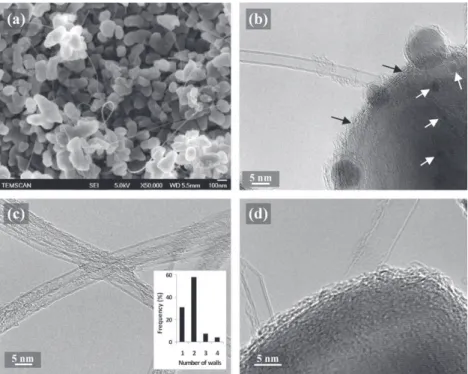
SEM observations showed long, smooth and flexible car-bon filaments (Fig. 1a) which corresponds to the characteris-tics of few-walled CNTs individual or in bundles. We verified by SEM that these filaments were homogeneously dispersed and that their quantity was lower in C1 (not shown) than in C2 (Fig. 1a). Thus, although the catalytic nanoparticles are not generated in situ from an oxide solid solution[3], a high homogeneity is preserved using the preparation of the cata-lytic material by the impregnation method. The size and shape of the alumina grains (Fig. 1a) were not modified during the CCVD process and are thus representative of the alumina powder used to prepare all composites (C1–C4) and ceramics (A1 and A2).
HRTEM images of C2 (Fig. 1b–d) show that the CNTs are mainly DWCNTs. A statistic study operated on HRTEM images of 120 CNTs (insert in Fig. 1c) reveals a great majority of DWCNTs (60%) and SWCNTs (30%), and a quite large outer diameter distribution (not shown) between 1 and 3.5 nm. Cat-alytic nanoparticles are evidenced onFig. 1b, some smaller than 4 nm (white arrows) which could have catalyzed the for-mation of a CNT and other larger (7–13 nm), which are cov-ered by several graphene sheets and have thus not been active for a CNT growth. Moreover, almost all the alumina grains are covered by a carbon film, between 1 and 3 nm thick, mainly disorganized but also crystallized in some of its places, as shown inFig. 1b (black arrows) andFig. 1d. The characteristics of as-prepared DWCNTs samples used in C3
and C4 have been described in Ref.[21]: about 80% DWCNTs, 15% SWCNTs, and outer diameters between 1 and 3 nm.
For C2, C3 and C4, Raman spectra recorded on as-prepared and functionalized CNTs, and on composite powders are re-ported in Fig. 2a–c. The high-frequency range (1000– 1800 cmÿ1) of all the Raman spectra shows both the D band
(ca. 1322–1333 cmÿ1) and the G band (ca. 1580–1588 cmÿ1).
The ratio between the intensities (ID/IG) is reported inTable 1.
For C2, the shoulder on the G band around 1620 cmÿ1,
de-tected on spectra of both the powder and the sintered com-posite, is a D0 band whom the intensity is important (30–
40% of the G band) in very disordered carbons[25]. Thus Ra-man spectroscopy well correlates the HRTEM results obtained on the C2 powder (Fig. 1b and d) and SEM results shown here-after on the C2 sintered composite (Fig. 3e). For all CNTs and composites, the radial breathing modes (RBM) are observed in the low-frequency range (100–300 cmÿ1) (inserts inFig. 2a–c).
The peak frequencies are inversely proportional to the CNTs diameters. According to calculations, the detected diameters are in the range 0.9–2.3 nm which is in good correlation with the above HRTEM results on C2 (the larger diameter CNTs being not detected by RBM) and with the characteristics of as-prepared DWCNTs[21]for C3 and C4. The small peak at about 1400 cmÿ1which appear on the spectra of C3 (Fig. 2b)
will be discussed in the sintered materials section. The ID/IG
for the C1 and C2 composite powders are very high when compared to that for C3 and C4 (Table 1). An increasing ID/
IGvalue corresponds to a higher proportion of sp3-like carbon,
which is generally attributed to the presence of more struc-tural defects in CNTs. However, HRTEM observations of the C2 powder revealed that CNTs where well crystallized (Fig. 1b–d), without more defects than DWCNTs used for C3 and C4. Thus, we infer that this high ID/IG value, which
correlates the presence of the high D0 band, is mainly due
the high quantity of disordered carbon which covers the alumina grains and some parts of the CNTs (Fig. 1b–d). For C3 and C4, the evolution of ID/IG values could reflect the
possible damaging of the CNTs during each step of the composite preparation. For C3, the change is not significant after the ultrasonic mixing, whereas for C4, the ratio has in-creased firstly from 13% to 24% after the covalent functional-ization and secondly from 24% to 53% after the ultrasonic mixing. Inevitably, defects are created by the covalent functionalization (sample C4) and the resulting CNTs are
Table 2 – Characteristics and properties of pure alumina and composites: SPS temperature, relative density and average matrix grain sizes, electrical conductivity (re), Vickers hardness (Hv), bending fracture strength (rf) and SENB fracture
toughness (KIC). Each value is the average of ten (Vickers hardness) or seven measurements (other mechanical properties);
standard deviations are mentioned.
Samples Composition Carbon (wt.%) T (SPS) (°C) Relativedensity (%) Average grain size (nm)
Hv (GPa) rf(MPa) KIC(MPa.mm1/2) re(S cmÿ1)
A1 Al2O3 – 1350 99 ± 1 1200 22.0 ± 0.4 484 ± 150 5.0 ± 0.3 – A2 Al2O3 – 1150 100 ± 1 320 21.3 ± 1.5 413 ± 84 5.4 ± 1.4 – C1 CNT–Al2O3 1.9 1350 97 ± 1 100 17.3 ± 1.1 – – 2.21 C2 CNT–Al2O3 3.1 1350 98 ± 1 110 13.8 ± 1.5 – – 3.49 C3 CNT–Al2O3 2.0 1350 99 ± 1 280/750a 17.8 ± 1.7 533 ± 91 5.6 ± 0.5 0.99 C4 CNT–Al2O3 2.0 1350 99 ± 1 190 19.1 ± 1.6 541 ± 59 3.9 ± 0.3 1.80
prone to be less resistant to the ultrasonic treatment than non-functionalized DWCNTs used for C3. Thus, the use of functionalized DWCNTs would require decreasing the energy of sonication.
3.2. Sintered materials characteristics
The alumina samples (A1, A2) and the C3 and C4 composites have a relative density near 100% while that of C1 and C2 are
a
b
c
d
Fig. 2 – Raman spectra of the samples; from bottom to top: composite powder and sintered composite C2 (a); as-prepared DWCNTs, composite powder and sintered composite C3 (b); as-prepared DWCNTs, functionalized DWCNTs, composite powder and sintered composite C4 (c); alumina powder, sintered alumina A1 and A2 (d).
Fig. 1 – SEM (a) and HRTEM (b-d) images of the composite powder C2; white arrows point towards small catalytic
nanoparticles and black arrows point towards the carbon film on an alumina grain (b); distribution of the number of walls of CNTs in C2 calculated from about 120 CNTs HREM images (insert in (c)).
smaller (97%,Table 2). SEM images of fracture surfaces (Fig. 3) allow one to describe the microstructure of the sintered mate-rials. The A1 ceramic (Fig. 3a), which was sintered at 1350 °C, i.e. at the temperature used for the composites, presents much larger grains (average size 1.2 lm) than composites samples (Fig. 3c–h, Table 2) in which the CNTs inhibit the grain growth of alumina, as shown by several authors [1,2,26]. Because the grain size has a significant influence on mechanical properties, the other ceramic specimen (A2) was
sintered at a lower temperature to obtain a grain size closer to that of composites. Indeed, the SPS treatment at only 1150 °C allows to fully densify A2 while retaining an average grain size at 320 nm (Fig. 3b, Table 2) [20]. The C1 (Fig. 3c and d) and C2 (Fig. 3e) samples present same average grain sizes (around 140 nm) which are equal to that of the starting powder, which means that these samples have been densified up to 97% without significant grain growth. Long and flexible CNTs appear at a moderate magnification (Fig. 3c) but Fig. 3 – SEM images of sintered ceramics and composites; pure alumina A1 (a) and A2 (b); composite C1 (c, d) – white arrows in (d) point towards CNT residues; composite C2 (e) – white arrows indicate carbon films; composite C3 (f), composite C4 (g–h) – white arrows in (h) indicate damaged CNTs.
residues of CNTs are also evidenced at higher magnification (arrows onFig. 3d) which traduces the damage of a part of CNTs, probably SWCNTs or individual CNTs which are less resistant to damage than DWCNTs and bundles respectively. Moreover, in spite of an inter-granular fracture, the alumina grains seem to be less facetted when compared to grains in pure alumina (Fig. 3a and b) or other composites (C3 and C4, Fig. 3f–h). This is explained by the presence of carbon films between the matrix grains as evidenced inFig. 3e. Indeed, the disordered carbon detected by HRTEM (in the C2 powder) on all alumina grains has not been removed during the SPS treatment which was performed under a primary vacuum atmosphere. Due to these carbon films, the alumina grains cannot grow and the full densification cannot be reached. This also correlates well with the high ID/IGratio and the
pres-ence of the high D0 band in the Raman spectrum of C2
(Fig. 2a–Table 1). The higher ID/IGratio of the sintered
compos-ites C1 and C2, compared to that for the composite powder, shows that a part of CNTs have been damaged during the SPS treatment. Huang et al.[27]reported that during such a treatment, the high current which runs through the ceramic matrix composite induce significant damages to CNTs and that these damages could be avoided when layers of an insu-lating materials are inserted between the punches and the sample. The two bands which appear at about 1370 and 1400 cmÿ1 on all spectra of sintered composites (Fig. 2a–c)
also appear on the spectra of the alumina powder and sin-tered ceramics A1 and A2 (Fig. 2d). These two bands have also been previously reported by Zhu et al. on both pristine alpha-alumina and on MWCNT–Al2O3composites[28]. We attribute
these bands to the fluorescence of Cr3+[29]explained by the
presence of this impurity in the alumina powder. The great enhancement of these peaks on the spectra of sintered mate-rials compared to that of the alumina and composite powders respectively (Fig. 2), could be attributed to a redistribution of Cr3+cations in the corundum structure during the SPS
treat-ment. Moreover, RBM peaks are observed in the low-fre-quency range which correlates well with the presence of undamaged CNTs shown on SEM images (Fig. 3c).
Catalytic nanoparticles have not been identified on SEM images but traces of cementite (Fe3C) and/or cFe-C have been
evidenced by X-ray diffraction analyses. The C3 sample, whose corresponding powder was prepared by ultrasonic-mixing of non-functionalized DWCNTs with alumina, pre-sents a bimodal distribution of the matrix grain size (Fig. 3f) explained by the presence of CNTs in some areas, in which they inhibit the grain growth (average size 280 nm –Table 2) and their quasi-absence in other areas in which the alumina grains are more free to grow (average size 750 nm –Table 2).
We noted that these two kinds of areas are interpenetrated and fairly well distributed in the sample. Evidently, the homo-geneous dispersion of the DWCNTs in the composite has not been fully achieved. Thus, we tried to improve the prepara-tion procedure of the composite powder for the C4 sample. The Raman spectra of C3 (Fig. 2b) shows a higher ID/IGratio
(21%) compared to the value for the corresponding powder (8%), but it remains quite low (Table 1), which traduces that most DWCNTs were not, or only slightly, damaged during the SPS treatment. Huang et al.[27], who used SWCNTs, re-ported a much higher ID/IGratio (230%) when the insulating
layers were not inserted between the punch and the sample compared to a ratio of only 40% when BN layers were in-serted. Thus, it seems that SWCNTs are much more sensitive to the high SPS current than the high quality DWCNTs used in the present work. The frequency of the G band (1595 cmÿ1) is
upshifted (+15 cmÿ1) compared to the composite powder.
Puech et al. [38] showed through in situ Raman spectroscopy of DWCNTs in a diamond anvil cell that there is a linear dependence between the shift in the frequency of the G-band and the applied isostatic pressure up to 12 GPa. Thus, this re-sult could suggest that the DWCNTs remain under residual pressure in the matrix, which could also reflect a good inter-action between Al2O3and CNTs. The RBM peaks are still
ob-served in the low-frequency range (Fig. 2b) and the peak splitting of the G band remains which confirms that most DWCNTs were not, or only slightly, damaged during the SPS treatment. Thomson et al. [14] reported the loss of the SWCNT structure for SPS treatment above 1250 °C. In the present work, the CNT structure is kept after the SPS treat-ment at 1350 °C maybe because most of them are DWCNTs which are supposed to be more resistant than SWCNTs. An-other explanation is that after high energy ball milling[14], SWCNTs become more prone to be damage by SPS, despite than defects are not evidenced on Raman spectra of compos-ite powders [14]. The C4 powder has been prepared using functionalized DWCNTs and the sonication was of higher en-ergy than for C3 because the probe was directly immersed in the suspensions. The result seen on SEM fracture surface images (Fig. 3g-h) is a much more homogeneous dispersion than for C3: there are no areas without CNTs and with a much larger alumina grain size. Indeed, we determine that the grain size distribution is unimodal, with an average value equal to 190 nm (Table 2), larger than that of in situ samples (C1, C2) but lower than the smallest grain population in C3. The inhi-bition of grain growth is thus more pronounced than in C3 be-cause of the better distribution of CNTs, but less pronounced than in C1 and C2 because in the latter samples, some disor-ganized carbon is located at the alumina grain boundaries, which do not allow for any grain growth. Some CNTs or CNT bundles seem undamaged (Fig. 3h) which is good corre-lation with the RBM peaks still observed in the Raman spec-trum (Fig. 2b), but some fragments of CNTs are also visible (Fig. 3h). The Raman spectra of C4 (Fig. 2c) do not show a high-er ID/IGratio in comparison with that of the powder (Table 1),
which means that the damages to the CNTs have mainly been produced during the first steps of the preparation procedure, i.e. during functionalization and probe sonication. As previ-ously seen for C3, the frequency of the G band (1596 cmÿ1)
is upshifted (+11 cmÿ1) compared to the composite powder
which could suggest that the DWCNTs remain under residual pressure in the matrix.
3.3. Electrical conductivity
All composites present an electrical conductivity of at least 1 S cmÿ1(r
e,Table 2) which is not surprising owing to the
car-bon contents of these CNT/ceramic composites higher than the percolation threshold measured by several authors [4–5,30]. However, for the four composites, the values are dif-ferent, which accounts for differences in the homogeneity of
the CNTs dispersion (C1, C3, C4) and in carbon content (C2). The C1 and C2 composites present the higher values, with an increase with the carbon content from C1 to C2. But the content of carbon in the form of CNTs is lower that the mea-sured carbon content when taking into account the disordered carbon located at grain boundaries. Possibly, this latter form of carbon contributes to increase the electrical conductivity at least by decreasing the contact resistance at CNT junctions. The higher value (3.5 S cmÿ1, sample C2) is thus obtained for
a CNT content lower than 3.1 wt.%. It is higher than that (0.24 S cmÿ1) reported by Rul et al.[4]for a similar content of
SWCNTs in MgAl2O4prepared by in situ synthesis and HP at
1300 °C but is lower than the values reported by Zhan et al. [31] for such a material (10.5 S cmÿ1for a 5.7 vol.% SWCNT/
Al2O3composite – i.e. about 2.7 wt.% SWCNT) which was
pre-pared by high energy ball milling and SPS at 1150 °C. Indeed, for a given carbon content, it is difficult to discriminate be-tween the many parameters, such as the quality and nature of the CNTs, preparation route of the powder, densification method and associated parameters which influence the value of the electrical conductivity of CNT/ceramic composites. In spite of same carbon contents, C3 present a lower value than C4 (Table 2), which could be due to the lesser homogeneity of the CNT dispersion. However, because the two kinds of area (with and without CNT) interpenetrate each other in C3, the electrical percolation is achieved. The electrical conductivity of C4, where CNT are well dispersed, is only slightly lower than that of C1 (Table 2), which shows that the preparation process of the C4 powder (functionalization, probe sonication and lyo-philisation) can generate a homogeneity of the CNT dispersion quite similar to the in situ synthesis. The damage to DWCNTs which mainly occurs during the powder preparation, as previ-ously revealed by Raman spectroscopy, does not seem to be deleterious to the conductivity.
3.4. Mechanical properties
The Vickers hardness of all composites (13.8–19.1 GPa,Table 2) is somewhat lower than that of the alumina samples (21.3– 22.0 GPa,Table 2). Alumina samples present a similar value showing that the influence of the average grain size seems low in the corresponding range (0.3–1.2 lm). The low hard-ness of C1 and C2 (17.3 and 13.8 GPa respectively) is more probably due to the residual porosity (3%) and to the presence of carbon films at the grain boundaries than to the presence of CNTs. The value is much lower for C2 than for C1 because of the higher carbon content and consequently to more car-bon films at grain boundaries. The hardness of C3 and C4 (17.8 and 19.1 GPa, respectively) is significantly higher, but are lower than that of alumina, in spite of the absence of residual porosity. The higher value for C4 can be correlated with its uniform microstructure and homogeneous disper-sion of DWCNTs. With a magnesia matrix, a twofold increase of hardness was obtained with 2.3 wt.% DWCNTs[18]but it was correlated with a grain size refinement and the low hard-ness of MgO (7.5 GPa) was more prone to be improved by a di-rect mechanical effect of DWCNTs than that of alumina which is already high (21.3 GPa for A2). Moreover, only An et al.[32], which used 4.1 wt.% large diameter MWCNTs, re-ported a significant increase of hardness in CNT/alumina
composite, compared with alumina of a similar submicronic average grain size. But to date and to the best of our knowl-edge, such an effect was never confirmed by other authors. The fracture strength (rf) and fracture toughness (KIc) were
measured only on C3 and C4 composites. The values are com-pared to those measured on the alumina samples (A1 and A2). Indeed, we did not succeed to prepare test specimens with the C1 and C2 pellets because of a too low cohesion probably due to the carbon films located at grain boundaries. Com-pared to both alumina samples, C4 presents higher fracture strength but lower fracture toughness (Table 2). For an aver-age grain size not much different (190 vs 300 nm), the fracture strength of C4 is 31% higher than that of A2 and both show mainly an intergranular fracture mode (Fig. 3b and g). On the opposite, A1 which presents a much higher average grain size (1.2 lm) shows a marked transgranular fracture mode (Fig. 3a). This change in fracture mode seems rather to be a consequence of the matrix grain refinement than of the pres-ence of CNTs at the grain boundaries. The fracture strength of C3 is similar to that of C4 and the fracture mode is intergran-ular in the small grain areas (280 nm), where the CNTs are lo-cated, but is mainly transgranular in the larger grain areas (750 nm –Table 2–Fig. 3f). This in agreement with the differ-ence of fracture mode observed between A2 and A1. The frac-ture toughness of C3 (5.6 MPa m1/2) is much higher than that
of C4 and slightly higher (+10%) or similar than that of A1 and A2, respectively (Table 2). Although the fracture toughness of A1, A2 and C3 are close to each other, the tendency is that that of A2 (average grain size of 320 nm), which shows an intergranular fracture mode, is slightly higher than that of A1 (average grain size of 1200 nm), which shows a partly transgranular fracture mode. Thus the microstructure of A2 seems more favorable than that of A1. The composite C3 shows a mixed microstructure (280/750 nm) with intergranu-lar and partly transgranuintergranu-lar fractures modes, respectively. Thus, both the microstructure and fracture modes of C3 are a mix between those of A1 and A2. However, its toughness is not lower but slightly higher than that of A2, and its frac-ture strength is higher. These differences let us think that CNTs could contribute to the high toughness and possibly the high fracture strength of C3. Taking only into account the values obtained by a SENB type method, only a few authors have reported similar[33,34]or higher (6.8 MPa m1/2)
[35] fracture toughness on CNT/Al2O3 composites but all of
them used MWCNTs and comparisons with alumina of a sim-ilar grain size were never conducted. For DWCNT/Al2O3
com-posites (5 vol.% CNTs) prepared by high-energy ball-milling and fully densified by SPS at 1250 °C, the fracture toughness was only 3.5 MPa m1/2 [14]. To investigate into more details
the possible mechanisms of crack deflection or crack bridging by the DWCNTs, Vickers patterns taken on polished surfaces of C3 and C4 samples were performed using a high load (2 kg) in order to deliberately produce cracks, which were observed by SEM (Fig. 4). A low magnification image of C3 (Fig. 4a) re-veals that the crack beginning at the left of the image runs across two kinds of areas, firstly a rough one (c), then a very flat one (b) and then a rough one again. The flat surface corre-sponds to an area with large grains (750 nm) and without CNTs whereas the others are areas with small grains (280 nm) and CNTs. In these areas, some alumina grains were
pulled-out during polishing making this surface rougher than in large-grain areas. The flat part (b) is enlarged in Fig. 3b where the crack deflected by some of alumina grains but without any CNT is observed. The rough part (c) is enlarged inFig. 3c where many carbon filaments (CNTs, individual or bundles) are observed bridging the crack (white arrows). They are more clearly observed on the enlargement of (d) inFig. 3d. Much more tauten filaments, located within the crack and bridging it are observed (Fig. 4e) in another part of a similar crack. These observations confirm that the mechanism of crack bridging could contribute to the high fracture toughness of C3. A similar investigation has been conducted for C4 (Fig. 4f) but a similar crack bridging was never detected. More-over, all filaments detected in the crack of C4 (arrows on Fig. 4f) are cut at a short distance from the matrix, maybe after pulling-out on a very short distance or after being un-folded and taught as the crack widens by grain boundary dec-ohesion[18]. A first explanation could be a stronger binding at the interface between the DWCNTs and the matrix than for C3 which would result from the functionalization of the CNTs
used for C4. However, because the fracture toughness of the latter sample is low and because of the damage to the DWCNTs evidenced by Raman spectroscopy (Table 2), it is rather proposed that the DWCNTs have become much less resistant when compared to that of C3 and are thus broken at a lower stress than for the as-prepared DWCNTs. Yamam-oto et al.[36]reported that defects can cause stress concen-trations and then decrease the strength of MWCNTs. Thus, in spite of a lesser homogeneity and its bimodal grain size distribution, C3 is the only sample which presents both a high fracture toughness and a fracture strength, similar or higher (+30%), respectively, than the values found for A2.
The observed crack-bridging by DWCNTs is comparable to that observed in DWCNT/MgO composites[18], but both the fracture toughness value and the increase compared to the pure matrix do not reach what is obtained in the DWCNT/ MgO (from 3.4 to 6.7 MPa m1/2)[18]. However, the present
re-sults are promising and justify to conduct further works on DWCNT/Al2O3composites in order to improve the dispersion
of the DWCNTs up to reach that obtained in C4 while keeping Fig. 4 – SEM images of cracks made by Vickers indentation using a high load (2 kg) on C3 (a–e) and C4 (f); details of an area with and without CNTs (b and c respectively); white arrows indicate CNTs or CNT bundles bridging the crack in C3 (c); detail of the crack bridging at a higher magnification (d) or in another crack of the same sample C3 (e); white arrows indicate broken CNTs within a crack in C4 (f).
CNTs undamaged as in C3 which will require no functionali-zation or only soft functionalifunctionali-zation (maybe non covalent) and/or sonication with a moderate energy, while keeping the lyophilisation method as a drying step.
4.
Conclusion
DWCNT/Al2O3composite powders with low carbon contents
(2–3 wt.%) have been prepared using three different methods and have been densified by spark plasma sintering. It is shown that specimens prepared by moderate-energy sonica-tion of as-prepared DWCNTs with submicronic alumina pres-ent a fracture strength higher (+30%) and a fracture toughness similar (5.6 vs 5.4 MPa m1/2) to alumina with a similar
submi-cronic grain size. This is correlated with crack-bridging by CNTs on a large scale, despite a lack of homogeneity of the CNT distribution. Specimens prepared using high-energy son-ication of covalent-functionalized DWCNTs are much more homogeneous and also present a high fracture strength but fracture toughness is poor, which is correlated with the ab-sence of crack-bridging probably due to a too low tensile strength of the CNTs resulting from their damaging during functionalization and sonication. Samples prepared by in situsynthesis in impregnated alumina are highly homoge-neous, as revealed by a high electrical conductivity (2.2– 3.5 S cmÿ1), but a disordered carbon deposit on the alumina
grains inhibits densification and grain growth (<200 nm) and the resulting intergranular carbon films induces a poor cohe-sion of the materials. These results are important guidelines for further studies of alumina reinforcement by DWCNTs, showing that a particular attention must be paid to the degree of damaging of the CNTs and matrix grain size. In particular, covalent functionalization and high-energy sonication (as well as high-energy ball milling) have to be avoided but mod-erate-energy sonication and lyophilisation can be included in the composite powder preparation route.
Acknowledgments
The authors thank U. Kus for his help in the preparation and characterization of some samples and G. Chevallier for assis-tance with the SPS, which was performed at the ‘‘Plateforme Nationale CNRS de Frittage Flash’’. The FESEM and HRTEM observations at TEMSCAN, the ‘‘Service Commun de Micros-copie Electronique a` Transmission’’, Universite´ Paul-Sabatier (Toulouse). The authors thank L. Datas for assistance in the HREM observations. Raman spectroscopy analyses were per-formed at the ‘‘Service commun de spectroscopie’’ of Univer-site´ Paul-Sabatier (Toulouse). The authors thank Dr P. Puech (CEMES) for assistance in the interpretation of Raman spec-troscopy results.
R E F E R E N C E S
[1] Cho J, Boccaccini AR, Shaffer MSP. Ceramic matrix composites containing carbon nanotubes. J Mater Sci 2009;44(8):1934–51.
[2] Zapata-Solvas E, Gomez-Garcia D, Dominguez-Rodriguez A. Towards physical properties tailoring of carbon nanotubes-reinforced ceramic matrix composites. J Eur Ceram Soc 2012;32(12):3001–20.
[3] Peigney A, Laurent C, Dobigeon F, Rousset A. Carbon nanotubes grown in situ by a novel catalytic method. J Mater Res 1997;12(3):613–5.
[4] Rul S, Lefevre-schlick F, Capria E, Laurent C, Peigney A. Percolation of single-walled carbon nanotubes in ceramic matrix nanocomposites. Acta Mater 2004;52(4):1061–7. [5] Ahmad K, Pan W, Shi SL. Electrical conductivity and dielectric
properties of multiwalled carbon nanotube and alumina composites. Appl Phys Lett 2006;89(13).
[6] Sheldon BW, Curtin WA. Nanoceramic composites: tough to test. Nat Mater 2004;3(8):505–6.
[7] Quinn GD, Bradt RC. On the vickers indentation fracture toughness test. J Am Ceram Soc 2007;90(3):673–80. [8] Ahmad I, Cao HZ, Chen HH, Zhao H, Kennedy A, Zhu YQ.
Carbon nanotube toughened aluminium oxide nanocomposite. J Eur Ceram Soc 2010;30(4):865–73. [9] Yoshizawa Y, Toriyama M, Kanzaki S. Preparation of high
fracture toughness alumina sintered bodies from bayer aluminum hydroxide. J Ceram Soc Jpn 1998;106(12):1172–7. [10] Yamamoto G, Shirasu K, Hashida T, Takagi T, Suk JW, An J,
et al. Nanotube fracture during the failure of carbon nanotube/alumina composites. Carbon 2011;49(12):3709–16. [11] Bichoutskaia E, Ershova OV, Lozovik YE, Popov AM. Ab initio
calculations of the walls shear strength of carbon nanotubes. Tech Phys Lett 2009;35(7):666–9.
[12] Kis A, Jensen K, Aloni S, Mickelson W, Zettl A. Interlayer forces and ultralow sliding friction in multiwalled carbon nanotubes. Phys Rev Lett 2006;97(2).
[13] Wang XT, Padture NP, Tanaka H. Contact-damage-resistant ceramic/single-wall carbon nanotubes and ceramic/graphite composites. Nat Mater 2004;3(8):539–44.
[14] Thomson KE, Jiang D, Yao W, Ritchie RO, Mukherjee AK. Characterization and mechanical testing of alumina-based nanocomposites reinforced with niobium and/or carbon nanotubes fabricated by spark plasma sintering. Acta Mater 2012;60(2):622–32.
[15] Zapata-Solvas E, Poyato R, Gomez-Garcia D, Dominguez-Rodriguez A, Radmilovic V, Padture NP. Creep-resistant composites of alumina and single-wall carbon nanotubes. Appl Phys Lett 2008;92(11):111912.
[16] Mukhopadhyay A, Chu BTT, Green MLH, Todd RI.
Understanding the mechanical reinforcement of uniformly dispersed multiwalled carbon nanotubes in alumino-borosilicate glass ceramic. Acta Mater 2010;58:2685–97. [17] Ye F, Liu LM, Wang YJ, Zhou Y, Peng B, Meng QC. Preparation
and mechanical properties of carbon nanotube reinforced barium aluminosilicate glass-ceramic composites. Scripta Mater 2006;55(10):911–4.
[18] Peigney A, Garcia FL, Estournes C, Weibel A, Laurent C. Toughening and hardening in double-walled carbon nanotube/nanostructured magnesia composites. Carbon 2010;48(7):1952–60.
[19] Laurent C, Flahaut E, Peigney A. The weight and density of carbon nanotubes versus the number of walls and diameter. Carbon 2010;48(10):2994–6.
[20] Santanach JG, Weibel A, Estournes C, Yang Q, Laurent C, Peigney A. Spark plasma sintering of alumina: Study of parameters, formal sintering analysis and hypotheses on the mechanism(s) involved in densification and grain growth. Acta Mater 2011;59(4):1400–8.
[21] Flahaut E, Bacsa R, Peigney A, Laurent C. Gram-scale CCVD synthesis of double-walled carbon nanotubes. Chemical Communications, (Cambridge, United Kingdom) 2003;12:1442–3.
[22] Flahaut E, Peigney A, Laurent C, Rousset A. Synthesis of single-walled carbon nanotube-Co–MgO composite powders and extraction of the nanotubes. J Mater Chem
2000;10(2):249–52.
[23] de Andrade MJ, Lima MD, Skakalova V, Bergmann CP, Roth S. Electrical properties of transparent carbon nanotube networks prepared through different techniques. Phys Status Solidi-R 2007;1(5):178–80.
[24] Brown WF, Srawley JE. Plane strain crack toughness testing of high strength metallic materials. Philadelphia, PA: ASTM; 1966. ASTM Spec Tech Pub. 410
[25] Vidano R, Fischbach DB. New lines in Raman-spectra of carbons and graphite. J Am Ceram Soc 1978;61(1–2):13–7. [26] Flahaut E, Peigney A, Laurent C, Marliere C, Chastel F, Rousset
A. Carbon nanotube-metal-oxide nanocomposites: microstructure, electrical conductivity and mechanical properties. Acta Mater 2000;48(14):3803–12.
[27] Huang Q, Jiang DT, Ovid’ko IA, Mukherjee A. High-current-induced damage on carbon nanotubes: the case during spark plasma sintering. Scripta Mater 2010;63(12):1181–4.
[28] Zhu YF, Shi L, Zhang C, Yang XZ, Liang J. Preparation and properties of alumina composites modified by electric field-induced alignment of carbon nanotubes. Appl Phys A: Mater 2007;89(3):761–7.
[29] Lemoine P, Quinn JP, Maguire P, McLaughlin JA. Comparing hardness and wear data for tetrahedral amorphous carbon and hydrogenated amorphous carbon thin films. Wear 2004;257(5–6):509–22.
[30] Poorteman M, Traianidis M, Bister G, Cambier F. Colloidal processing, hot pressing and characterisation of electroconductive MWCNT–alumina composites with compositions near the percolation threshold. J Eur Ceram Soc 2009;29:669–75.
[31] Zhan GD, Kuntz JD, Garay JE, Mukherjee AK. Electrical properties of nanoceramics reinforced with ropes of single-walled carbon nanotubes. Appl Phys Lett 2003;83(6): 1228–30.
[32] An JW, Lim DS. Effect of carbon nanotube additions on the microstructure of hot-pressed alumina. J Ceram Process Res 2002;3(3):201–4.
[33] Fan J, Zhao D, Wu M, Xu Z, Song J. Preparation and microstructure of multi-wall carbon nanotubes-toughened Al2O3composite. J Am Ceram Soc 2006;89(2):750–3.
[34] Yamamoto G, Omori M, Hashida T, Kimura H. A novel structure for carbon nanotube reinforced alumina composites with improved mechanical properties. Nanotechnology 2008;19(31).
[35] Ahmad I, Unwin M, Cao H, Chen H, Zhao H, Kennedy A, et al. Multi-walled carbon nanotubes reinforced Al(2)O(3) nanocomposites: mechanical properties and interfacial investigations. Compos Sci Technol 2010;70(8):1199–206. [36] Yamamoto G, Suk JW, An JH, Piner RD, Hashida T, Takagi T,
et al. The influence of nanoscale defects on the fracture of multi-walled carbon nanotubes under tensile loading. Diam Relat Mater 2010;19(7–9):748–51.