O
pen
A
rchive
T
OULOUSE
A
rchive
O
uverte (
OATAO
)
OATAO is an open access repository that collects the work of Toulouse researchers and
makes it freely available over the web where possible.
This is an author-deposited version published in :
http://oatao.univ-toulouse.fr/
Eprints ID : 19351
To link to this article :
URL :
http://dx.doi.org/10.1021/acsnano.7b01328
To cite this version :
Ghedjatti, Ahmed and Magnin, Yann and Fossard, Frédéric and
Wang, Guillaume and Amara, Hakim and Flahaut, Emmanuel and
Lauret, Jean-Sébastien and Loiseau, Annick Structural Properties
of Double-Walled Carbon Nanotubes Driven by Mechanical
Interlayer Coupling. (2017) ACS Nano, vol. 11 (n° 5). pp.
4840-4847. ISSN 1936-0851
Any correspondence concerning this service should be sent to the repository
administrator:
[email protected]
Structural Properties of Double-Walled Carbon
Nanotubes Driven by Mechanical Interlayer
Coupling
Ahmed Ghedjatti,
†Yann Magnin,
‡Frédéric Fossard,
†Guillaume Wang,
§Hakim Amara,
*
,†Emmanuel Flahaut,
⊥Jean-Sébastien Lauret,
∥and Annick Loiseau
*
,††Laboratoire d’Etude des Microstructures, ONERA-CNRS, BP 72, 92322 Châtillon Cedex, France
‡Aix-Marseille University and CNRS, CINaM UMR 7325, 13288 Marseille, France
§Laboratoire Matériaux et Phénomènes Quantiques, CNRS-Université Paris 7, 10 Rue Alice Domon et Léonie Duquet, 75205 Paris
Cedex 13, France
⊥Centre Inter-universitaire de Recherche et d’Ingénierie des Matériaux (CIRIMAT), CNRS UMR 5085, Université Paul-Sabatier,
31062 Toulouse, France
∥Laboratoire Aimé Cotton, CNRS, Univ. Paris-Sud, ENS Cachan, Université Paris-Saclay, 91405 Orsay Cedex, France
*
S Supporting InformationABSTRACT: Structural identification of double-walled carbon nanotubes (DWNTs) is
presented through a robust procedure based on the latest generation of transmission electron microscope, making possible a statistical analysis based on numerous nano-objects. This approach reveals that inner and outer tubes of DWNTs are not randomly oriented, suggesting the existence of a mechanical coupling between the two concentric walls. With the support of atomic-scale modeling, we attribute it to the presence of incommensurate domains whose structures depend on the diameters and helicities of both tubes and where inner tubes try to achieve a local stacking orientation to reduce strain effects.
KEYWORDS: DWNT, HRTEM, statistical analysis, mechanical coupling, atomic-scale modeling
D
ouble-walled carbon nanotubes (DWNTs) haveattracted the attention of numerous scientists because their intrinsic coaxial structures lead to exciting applications.1−3 From a fundamental point of view, they are highly attractive since they represent the simplest system for investigating the effect of the interwall coupling on the physical properties of multiwalled carbon nanotubes. As for hetero-structures built from two-dimensional crystals,4this interaction can be the cause of unexpected physical properties that are not well-known for the moment. Therefore, a detailed under-standing of the interlayer coupling is still mandatory for designing more elaborate applications of DWNTs.
Intertube electronic coupling in the case of DWNTs can depend on the mutual arrangement of the tube walls defined by the interwall spacing and the relative rotation (or twist angle) between their hexagonal networks.5−7 For instance, a strong intertube coupling that can induce a semiconductor-to-metal
transition has been predicted for commensurate DWNTs.6
Incommensurate DWNTs were also studied.8−12 It was
recently shown that the DWNT resulting from the combination of two concentric single-walled carbon nanotubes (SWNTs) can end up with nontrivial electronic properties, depending on
the twist angle.12 The impact of the structure of DWNTs on
their spectroscopic properties has also been explored. Detailed Raman studies on individual DWNTs have established that both walls are mechanically coupled via the interlayer van der Waals interaction.13−16 Finally, recent measurements using optical absorption spectroscopy have shown that van der Waals interaction can strongly shift optical transition energies and is highly dependent on the helicity indices of each layer.17
In this context, an accurate knowledge of the structure of DWNTs is needed to reach a full understanding of the interactions between layers and their impact on the electronic properties. To do so, it is necessary to perform a statistical study on a large number of DWNTs to determine whether inner and outer tubes are randomly oriented to each other or not and subsequently whether they are coupled or not. Such investigations face some challenges. The first difficulty lies in the lack of synthesis routes to pure, electronically well-defined
raw material.18−20 However, the main challenge is the
identification of the structure itself. A complete identification of (n, m) indices of each layer of a DWNT can be extracted
from the electron diffraction pattern recorded in a transmission electron microscope (TEM).14,17,21−25Although very powerful, it can be operated only on long, straight, and isolated tubes in such a way that the electron beam illuminates solely a tube area larger than its structure periodicity. The identification of the structure can also be performed by using phase contrast high-resolution imaging (the so-called HRTEM technique). This
technique has suffered for a long time from a too low image
resolution to provide atomically resolved images of carbon sp2
structures. This is no longer the case with the use of a TEM equipped with aberration correctors and delivering resolution below 100 pm. Indeed, the direct identification of the (n, m) chiral indices of SWNTs from atomically resolved images has been recently reported by Warner et al.26
In this article, we present a statistical study of the structure of
DWNTs based on their identification from atomically resolved
images recorded with a HRTEM. The DWNTs are produced by the chemical vapor deposition (CVD) technique described in ref27since they serve as long-standing reference samples in
several works.28−31 We show that inner and outer tubes of
DWNTs are not randomly oriented to each other, suggesting a strong coupling between both walls. The nature of the interwall interaction is discussed with the support of atomic-scale modeling. This leads to the conclusion that the respective orientation of the inner and outer tubes minimizes strain effects.
RESULTS AND DISCUSSION
Our sample produced by CVD techniques27,32is a mixture of
different structural configurations in terms of diameter and
helicity. A systematic analysis of TEM images reveals that samples produced by this method contain approximately 66% DWNTs with a small admixture of about 20% single-walled carbon nanotubes and roughly 12% triple-walled carbon nanotubes. In these experiments, the DWNTs have an outer diameter between 1.2 and 4 nm and an average inner diameter around 1.8 nm (see Figure S1 of theSupporting Information). Although great care is taken to disperse properly DWNTs on TEM grids, tubes are most often entangled, so that electron diffraction can hardly be recorded from isolated tubes.
Procedure for DWNT Structure Determination with HRTEM. A complete structure identification is provided by the knowledge of the pair of Hamada indices (ni, mi)@(no, mo)
where (ni, mi) and (no, mo) stand for chiral indices of inner and outer tubes, respectively. They can be extracted from geometrical parameters: the inner and outer tubes diameters, Diand Do, and their respective helicitiesθi andθo.33Here, we
focus on HRTEM images26 and examine how they can be
exploited in the complex situation of a DWNT.
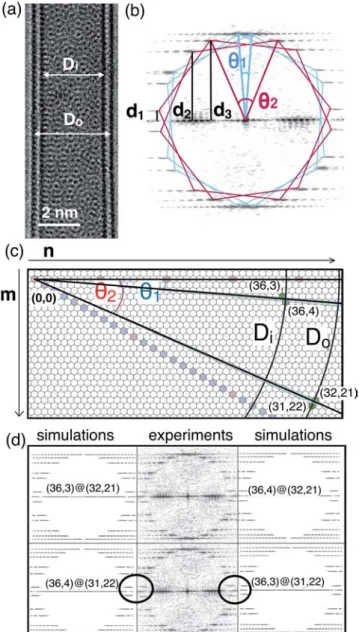
Figure 1a presents a typical atomically resolved HRTEM image of a DWNT. Basically, it displays a complex contrast
moiré pattern that arises from the projected view of four
rotated hexagonal networks. Three rotation angles are involved: the two helicity angles (θiandθo) and the twist angle between the tubes,Δθ, defined as ∥θi| − |θo∥. As a result, the complexity
of the moiré figure hinders the direct reading of the atomic structure.
In order to achieve a fully atomic-resolved structure
reconstruction from such an image, we defined a data
processing sequence composed of different steps. It combines
analysis in real and Fourier spaces and the simulation of images based on the exact experimental TEM conditions. Thefirst step consists in the determination of the diameters from intensity
profiles related to the set of dark and bright fringes lying on
each side of the tube image (see Figure S2 of theSupporting
Information for details of the assignment).34 Diameters are
determined with an error of∼0.05 nm.
The second step consists in extracting helicities from the numerical fast Fourier transform (FFT) of the image. This numerical diffraction pattern displays the same features as an
experimental electron diffraction. It consists in the
super-imposition of two series of punctuated layer lines related to inner and outer tubes, respectively, due to discrete translation invariance along the tube axis. First-order spots define four hexagons, two for the inner tube rotated from each other byθ1 and two for the outer tube, rotated from each other byθ2. As
Figure 1. (a) HRTEM images of a DWNT. (b) Its corresponding Fourier transform. From the measurement of the layer line spacings d2andd3, chiral angles can be obtained with an error bar of∼0.5°.
(c) Distribution of possible chiral indices after the analysis of the layer lines. This leads to four configurations colored in green: (36,3)@(32,21), (36,4)@(32,21), (36,4)@(31,22), and (36,3) @(32,22). (d) Comparison of the Fourier transform from the HRTEM image and simulated results for previous solutions: (36,4) @(31,22) and (36,3)@(31,22) can be ruled out because some differences (marked with circles) are noticed.
proposed in ref 21, the values of the helicity angles are accurately determined by considering spacings between the different layer lines d2and d3as defined inFigure 1b. The chiral angle is given by
θ = arctan((2d2−d3)/ 3 )d3
The values of the angles are obtained with an error ∼0.5°. Considering these helical angles (with error bars) and diameters of inner and outer tubes directly measured from HRTEM observations, the third step of the procedure consists in assigning all the possible (n, m) tubes according to the chiral map (Figure 1c). This leads to several possible pairs of (ni, mi)
@(no, mo) indices. Then, the comparison between the
experimental and the simulated FFT (see Figure 1d) allows
ruling out some configurations. The final step consists in the comparison between experimental and simulated images. The complex moiré pattern is indeed very sensitive to the (ni, mi)
and (no, mo) couples. Changing n or m indices by one unit, which corresponds to a change in one helicity angle of 0.1° or less, can induce dramatic changes since moiré patterns resulting from interferences of four walls in the case of DWNTs are very sensitive to the (ni, mi) and (no, mo) couples (seeFigure 2). A small change in the twist angle between the inner and outer
tube can significantly change the HRTEM images.
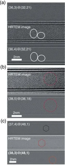
From this procedure, only the moiré pattern from the
simulated HRTEM image of a (36,4)@(32,21) DWNT canfit
with the experimental image in Figure 3a. Various examples
corresponding to different moiré patterns and twist angles are
shown in Figure 3. A broad spectrum of data is presented
illustrating that any kind of configuration can be accurately determined using this procedure. Detailed examples with all the
steps are shown in Figures S3 and S4 of the Supporting
Information. In this way, the chiral indices of DWNTs can be determined unambiguously from our robust procedure.
Statistical Analysis of DWNT Helicities. In order to emphasize a possible correlation between the DWNT layers, we examine whether there are preferred combinations of inner and outer tubes by analyzing the statistical distributions of different
structural parameters of ∼70 isolated DWNTs. Let us first
consider the interlayer distanceΔr, where Δr = (Do− Di)/2.
As seen in Figure S5, values of Δr are distributed over a
relatively wide range of 0.30 to 0.40 nm, close to that of bulk graphite (∼0.34 nm). More interestingly, the results show no significant correlation between Δr and Do, in agreement with
previous works24,35 (see Figure S5 of the Supporting
Information).
Then, the apparent differences in the chiral angles between inner and outer tubes are examined by analyzing the relationship between the helicities of outer tubes θo and Δθ.
The chirality distribution was discussed with respect to Δθ,
which implies the absolute value of the chiral angle, since we could not adequately distinguish right- or left-handed chirality from the experiment. As visualized inFigure 4a, the distribution of the chiral indices of the DWNTs is not homogeneous. Indeed, configurations corresponding to areas filled in gray are not observed, i.e.,Δθ = 0° and Δθ > 25°. The first exclusion
zone is not so surprising since commensurate DWNTs (Δθ =
0°) are rarely (or never) observed experimentally because it is unlikely to have two commensurate SWNTs with the
appropriate radius difference for the formation of a
DWNT.17,21,36 As for the second one, it suggests that inner and outer tubes are strongly correlated in such a way as to avoid twinning angles whereΔθ > 25°. Besides, some configurations are particularly favored and are highlighted by a red square in Figure 4a, where ∼50% of the nanotubes are observed. This zone fulfills two conditions: both helicities are near armchair andΔθ < 15°. In order to demonstrate the particular features of
Figure 2. Simulation images of (a) (36,3)@(32,21) DWNT and (b) (36,4)@(32,21) DWNT to illustrate how moiré patterns resulting from interferences of four walls in the case of DWNTs are very sensitive to the (ni,mi) and (no,mo) couples.
Figure 3. Comparison between experimental and simulated HRTEM images where the analysis of moiré patterns enables identifying the structure of the DWNT. (a) (36,3)@(32,21) and (36,4)@(32,21) DWNT (Δθ = 18.0°); (b) (38,5)@(38,18) DWNT (Δθ = 12.24°); (c) (38,3)@(48,1) DWNT (Δθ = 2.74°).
the relationship between θo and Δθ, we now consider the random orientation of both layers as reference data (seeFigure 4b). The distribution is calculated for all (ni, mi)@(no, mo) in the ranges of 1.5 < Do< 4 nm and 0.30 <Δr < 0.40 nm. As
seen inFigure 4b, favored and nonobserved configurations are expected to be distributed in red and gray triangles, respectively. Moreover, our calculations show a homogeneous and symmetric repartition with respect to 15° for both axes, in
strong contrast with our experimentalfindings. This supports
the conclusion that inner and outer tubes are not randomly oriented to each other. It is worth mentioning that the
correlation relates only to Δθ and has no impact on the
interlayer spacing as shown in Figure S5 of the Supporting
Information.
Using our criterion, we have also analyzed data found in the literature where DWNTs were prepared using the arc discharge
method24 and an other CVD technique17 to confirm the
intrinsic character of our results. In these works, structural analyses have been performed by using electron diffraction. One can note that the relationship between the helicities and Δθ has not been investigated in these previous works, making impossible the conclusions discussed here. By analyzing those experimental results with our procedure, similar conclusions to ours can be proposed in terms of favored (red square) and
forbidden configurations (gray area) (see Figure S6). As a
result, it can be concluded that the orientations of the hexagonal carbon network between the inner and outer tubes of DWNT are not independent and that this results does not depend on the synthesis technique nor on the method of analysis.
Mechanical Coupling between Layers. The next step is to identify the nature of the coupling, i.e., electronic and/or mechanical, that is responsible for previous observations. From the electronic point of view, all the SWNTs that form the DWNT can be classified according to their electronic nature by considering the chiral indices (ni, mi) and (no, mo). However, due to interlayer coupling, electronic properties of DWNTs can
differ from those of the constituent SWNTs. By using
theoretical arguments developed in ref 12 that take into
account this coupling, the electronic properties of the nanotubes characterized above have been determined. As
seen in Figure 4a, the distribution in terms of electronic
population is relatively homogeneous. Therefore, it can be concluded that the interwall coupling producing favored and forbidden configurations is unlikely to be driven by electronic effects.
Besides, in some isolated DWNTs, anomalous structures have been occasionally found, suggesting that a mechanical
coupling between walls can exist. Indeed, different HRTEM
observations have revealed the presence of defected DWNTs where only the inner tubes are damaged. As seen inFigure 5a, structural changes of the confined tube characterized by local deformations (highlighted by red arrows) are observed. In the present cases, the interlayer distance shows a variation along the tube axis. Indeed, the inner tube bends locally to decrease the distance with the outer wall. Previous works have already revealed the deformation of two neighboring DWNTs due to
van der Waals interactions present in the bundle.35 In this
situation, both walls sustained damage. This is clearly not the case here since only isolated DWNTs are considered. Moreover, the electron beam produced by TEM could also be at the root of these structural modifications. To test this assumption, TEM observations have been performed with a Philips CM20 operating at 120 kV.Figure 5b shows structural changes of a DWNT during the electron irradiation. Both walls are clearly damaged, indicating that when the deformation is observed solely on the inner tube, it is not due to the electron irradiation of the microscope. As a result, the presence of defected inner tubes suggests that a mechanical coupling exists between the walls. A mechanical coupling has already been reported using Raman spectroscopy,14,16but in the present case it is directly evidenced in the case of a DWNT by TEM investigations.
Atomic-Scale Simulations. We have performed atomic-scale simulations in order to get insight into the coupling between walls depending on whether the constituent nanotubes are commensurate or not. In the layered graphitic sheets, the interlayer interaction is dominated by the long-ranged van der Waals interaction. Therefore, empirical methods capable of
Figure 4. (a) Statistical analysis of∼70 DWNT helicities following our TEM procedure. (b) Random distribution ofΔθ for all (ni,mi)
and (no,mo) in the ranges 1.5 <Dm< 4.0 nm and 0.30 <Δr < 0.40
nm. In all cases, favored (red delimited area) and nonobserved (dashed gray area) configurations are marked.
predicting the equilibrium distance at the van der Waals distances are needed for studying large graphitic systems. In the present simulations, the atomic interaction is described by a potential developed by Che et al.37
First, relaxed structures have been obtained after performing rigid relaxation including translations and rotations of the inner
tube while the outer one is kept fixed. Using this approach,
commensurate as well as incommensurate DWNTs containing a large number of atoms (∼1000 to 10 000 atoms) are studied. Then, we analyze in a histogram form the local energies of carbon atoms of the inner tube to determine which C atoms gain some energy. As an example, results for the (14,8)@(23,9)
DWNT (Δθ = 5.23°), which has been observed experimentally,
are plotted in Figure 6a. The system contains ∼6000 atoms
corresponding to a tube length of∼20 nm. Two populations of
carbon atoms are identified. They correspond to a moiré
pattern displaying two kinds of local stacking. On one hand, regions where neighbor atoms are almost on top of each other, corresponding to the so-called AA stacking, are characterized by the highest interaction energy. On the other hand, since the walls are rotated, the well-known Bernal AB stacking is also observed, giving rise to the lowest interaction energy. These results are in agreement with ab initio calculations showing that AB-stacked bilayer graphene is the most stable structure.38,39 We consider now the case of the unexpected (19,1)@(19,14)
DWNT (Δθ = 22.46°) with ∼8000 atoms corresponding to a
tube length ∼25 nm. Only one population of C atoms is
evidenced (AB stacking), where their energies are slightly different from the previous example since diameters are not the
same (see Figure 6a). These configurations show a more
uniform pattern where AA stacking is no longer present. Other examples displaying the same local energy distributions are
discussed in the Supporting Information. Despite these
examples, local energy differences between stackings are not
significant enough (less than 1 meV/at) to explain the favored and forbidden configurations highlighted by our experiments.
Consequently, we have then considered geometrical argu-ments by investigating the spatial distributions of C−C first-neighbors intertube distances. This can be seen as a signature of
Figure 5. (a) HRTEM image of defected inner tubes in some isolated DWNTs. Local deformations of inner tubes are highlighted by red arrows. (b) Structural changes of DWNTs under electron irradiation.
the roughness between walls and therefore can be very helpful to identify a possible mechanical coupling in DWNTs. As seen in histogram plots presented inFigure 6b, both configurations
display the same C−C first-neighbors intertube distance
distribution. However, their spatial distributions along the inner tube are strongly different. In the case of the observed
(14,8)@(23,9) DWNT multiple domains of two different
Bernal-stacked configurations (AB vs AA stacking) coexist.
When looking at the C−C distance mapping, this DWNT
presents a smooth variation (illustrated by a wavy profile in Figure 6c), pointing out that roughness between both walls is soft. This behavior has also been identified in the case of an
observed (11,10)@(20,11) DWNT, as shown in Figure S7.
Both areas are present, and the roughness between walls is relatively poor. We thus show that the inner tube is subject to
weak stress effects. We now focus on the unobserved (19,1)
@(19,14) DWNT. As seen inFigure 6b, the mapping along the
inner tube differs strongly from that of the (14,8)@(23,9)
DWNT. Indeed, our analysis shows an irregular pattern that is highly pronounced where spatial distributions are sharp and discrete (see the sketch inFigure 6c). This indicates that inner and outer tubes interact strongly, resulting in rough intertube spacings. We can therefore attribute the nonobservation of the
(19,1)@(19,14) DWNT to the strain effects on the inner tube,
which tend to prevent this kind of stacking. Similarly, such mechanical coupling can explain the lack of commensurate
DWNTs for aΔθ equal (or close) to 0° (see Figure S7 of the
Supporting Information).
Lastly, we introduce the out-of-plane degrees of freedom by using Monte Carlo (MC) simulations40to relax the structures and analyze the nonstability of specific DWNTs. The idea is to start from different cases not found experimentally and submit them to high temperatures up to 3000 K, which is a typical temperature used in graphitization processes.41The system is then able to overcome high energy barriers and reach new states corresponding to equilibrium configurations. Using this procedure, the mechanisms explaining the stability of different DWNTs can be studied in detail.
We present two representative DWNTs, (10,0)@(18,0) and
(12,0)@(18,0), which are both commensurate withΔθ = 0°
and not supposed to be stable according to our HRTEM observations. We have deliberately chosen tubes with very small
interlayer distances Δr (0.31 and 0.27 nm, respectively) to
emphasize interlayer coupling and obtain relaxed structures in a reasonable, although long, CPU time. To mimic experimental observations where only the inner tube is subjected to
structural modifications, outer shells are kept fixed and no
periodic boundary conditions have been applied along the tube axis in order to allow the inner tube to relax completely.
Figure 7a shows thefinal states of the MC runs for a (10,0) @(18,0) DWNT at two temperatures (T = 2500 K and T = 3000 K) containing 672 atoms for a tube length close to 25 Å. At 2500 K, the spontaneous closing of the inner tube into a graphitic-like dome can be observed. This is not surprising since these edge relaxations are due to the presence of unstable dangling bonds. More interestingly, the inner tube moves along
the tube axis (displacement ∼0.2−0.3 nm) to minimize its
interaction with the outer shell, and the local stacking changes continuously during the simulation. This shows the nonstability of the initial structure since starting from a AA stacking thefinal configuration corresponds to a AB one. At higher temperature (T = 3000 K), spectacular structural changes are noticed. The
diameter and chiral angle are strongly modified, as seen in
Figure 7a, showing that configurations with Δθ = 0° are not stable at all. It is reasonable to think that the equilibrium
configuration should correspond to a DWNT with structural
parameters corresponding to favored configurations as
discussed inFigure 4. However, the relaxed structure presents important distortions and a lot of defects preventing a complete determination of its chirality. Despite that, our simulations emphasize that strain effects on the inner tube exist, leading to forbidden structures, as observed experimentally. In the case of a (12,0)@(18,0) DWNT, the system contains 720 atoms for a tube length close to 24 Å. The same conclusions can be drawn with stronger evidence due to the small interlayer distance, which increases the effects (seeFigure 7b). As an example, the diameter of the inner tube varies from 9.5 to 6.5 Å, in agreement with HRTEM observations of defected tubes where
in some cases the inner tube diameters decrease (seeFigure
7c). To conclude, an important issue derived from these results
is the confirmation that the inner tube can be subjected to
stress effects due to an interlayer coupling, explaining the
nonstability of particular configurations and the deformation of the inner tubes.
CONCLUSION
In summary, we have shown that both layers constituting DWNTs are not randomly oriented. Their structural properties are mainly driven by a mechanical interlayer coupling where the inner tube tries to achieve a local stacking in order to reduce strain effects. This can be achieved during their synthesis since it has been suggested that MWNTs grow by a layer-by-layer
Figure 7. (a) Relaxed configurations of (10,0)@(18,0) DWNT after MC simulations at 2500 and 3000 K. (b) Relaxed configuration of (12,0)@(18,0) DWNT after MC simulation at 3000 K. (c) Comparison between Monte Carlo simulations and defected DWNTs observed experimentally where the inner tube diameters decrease (as indicated with arrows).
mechanism.42−44In this scenario, the outer tube might start to grow; then inner walls are formed, which can be stabilized by a
lip−lip interaction.45 By repeating this growth process, a
nanotube can grow in length as well as in thickness. Recently some in situ TEM observations demonstrated this sequential nucleation processes in the case of DWNTs by using crystalline Pt as catalyst particle.46 Our work is in complete agreement with this proposed mechanism and highlights the directional correlation between two adjacent graphitic layers in a DWNT when it grows, to best accommodate strain effects on the inner tube. Meanwhile, the presence of favored configurations sheds light on the structural control of the DWNT. Indeed, the main hurdle in the development of a DWNT-based technology is to control their structure and more precisely to reduce their diameters for electronic applications.47,48 Starting from raw samples (containing SWNT, DWNTs, ...), several groups are working on the subsequent processing and sorting of raw material.19,20 By focusing on favored structures, realizing the ultimate goal of controlling chirality during sorting will be facilitated, enabling their use for a wide variety of potential applications.
METHODS
Double-wall carbon nanotubes were grown using a CVD method based on a thermal decomposition of CH4on Co:Mo-MgO.27,32TEM
observations have been performed with an aberration-corrected microscope, a JEM-ARM-200F, with a spatial resolution of 80 pm for an accelerating voltage of 80 kV. Simulated TEM images have been calculated within dynamical theory with a commercial code (JEMS49) and homemade software (DiffractX21,50).We have used the multislice
approach51 based on scattering factors given by Peng et al.52 and aberration coefficients corresponding to the JEM-ARM-200F.53
The cohesion in layered graphitic structures is a combination of long-ranged van der Waals and short-ranged orbital overlap contributions. Thefirst term implies a cutoff distance around 20 Å to reproduce correctly the interlayer energy in graphite.37To limit the CPU time of our MC simulations, only commensurate tubes have been considered when complete atomic relaxations have been investigated. The convergence of the total energy as a function of Monte Carlo steps is controlled and the simulation is stopped when the total energy no longer varies on average, which implies that the system has reached a Gibbs energy minimum. Typical runs consist of 103 external Monte Carlo loops, each of them randomly performing 103atomic displacements trials. The different tubes studied here were subjected to temperatures ranging from 1000 to 4500 K. At low temperature (T < 2500 K) no obvious structural modifications are observed since the system is trapped in a local minima. On the other hand, close to vaporization conditions (T > 4000 K), the tube is completely destroyed. To avoid this difficulty, simulations are performed at different temperatures ranging from 2500 to 3500 K. ASSOCIATED CONTENT
*
S Supporting InformationThe Supporting Information is available free of charge on the ACS Publications websiteat DOI:10.1021/acsnano.7b01328.
Analysis of the samples in term of population and diameter of tubes, supporting TEM data, distribution of structural parameters, analysis of data from the literature (PDF) AUTHOR INFORMATION Corresponding Authors *E-mail:[email protected]. *E-mail:[email protected]. ORCID Annick Loiseau: 0000-0002-1042-5876 Notes
The authors declare no competingfinancial interest.
ACKNOWLEDGMENTS
The research leading to these results has received funding from C’Nano Ile-de-France (project Biptec). Y.M and H.A. thank the European Union Seventh Framework Programme (FP7/2007-2013) under grant agreement no. 604472 (IRENA project). J.S.L. was partly funded by Institut Universitaire de France. G.W. acknowledges the support of the French Agence Nationale de la Recherche (ANR) under contract reference ANR-11-BS10-009. The authors wish to thank the METSA research foundation for giving access to the Cs-corrected TEM of MPQ-Paris Diderot laboratory. We are also grateful to the Region Ile-de-France for convention SESAME E1845 for the support of the JEM ARM 200F electron microscope installed at the Paris Diderot University. The authors acknowledge M. Kociak (DiffractX) and Y. Le Bouar for use of their software. F. Ducastelle, L. Marty, and P. Poncharal are acknowledged for helpful discussions.
REFERENCES
(1) Shen, C.; Brozena, A. H.; Wang, Y. Double-Walled Carbon Nanotubes: Challenges and Opportunities. Nanoscale 2011, 3, 503− 518.
(2) Kim, Y. A.; Yang, K.-S.; Muramatsu, H.; Hayashi, T.; Endo, M.; Terrones, M.; Dresselhaus, M. S. Double-Walled Carbon Nanotubes: Synthesis, Structural Characterization, and application. Carbon Lett. 2014, 15, 77−88.
(3) Moore, K. E.; Tune, D. D.; Flavel, B. S. Double-Walled Carbon Nanotube Processing. Adv. Mater. 2015, 27, 3105−3137.
(4) Geim, A. K.; Grigorieva, I. V. Van der Waals Heterostructures. Nature 2013, 499, 419−25.
(5) Okada, S.; Oshiyama, A. Curvature-Induced Metallization of Double-Walled Semiconducting Zigzag Carbon Nanotubes. Phys. Rev. Lett. 2003, 91, 216801−4.
(6) Zólyomi, V.; Rusznyák, Á.; Kürti, J.; Gali, Á.; Simon, F.; Kuzmany, H.; Szabados, Á.; Surján, P. Semiconductor-to-Metal Transition of Double Walled Carbon Nanotubes Induced by Inter-Shell Interaction. Phys. Status Solidi B 2006, 243, 3476−3479.
(7) Moradian, R.; Azadi, S.; Refii-tabar, H. When Double-Wall Carbon Nanotubes Can Become Metallic or Semiconducting. J. Phys.: Condens. Matter 2007, 19, 176209.
(8) Lambin, P.; Meunier, V.; Rubio, A. Electronic Structure of Polychiral Carbon Nanotubes. Phys. Rev. B: Condens. Matter Mater. Phys. 2000, 62, 5129−5135.
(9) Roche, S.; Triozon, F. m. c.; Rubio, A.; Mayou, D. Conduction Mechanisms and Magnetotransport in Multiwalled Carbon Nano-tubes. Phys. Rev. B: Condens. Matter Mater. Phys. 2001, 64, 121401−4. (10) Roche, S.; Triozon, F.; Rubio, A.; Mayou, D. Electronic Conduction in Multi-Walled Carbon Nanotubes: Role of Intershell Coupling and Incommensurability. Phys. Lett. A 2001, 285, 94−100.
(11) Uryu, S.; Ando, T. Electronic Intertube Transfer in Double-Wall Carbon Nanotubes. Phys. Rev. B: Condens. Matter Mater. Phys. 2005, 72, 245403−10.
(12) Koshino, M.; Moon, P.; Son, Y.-W. Incommensurate Double-Walled Carbon Nanotubes as One-Dimensional Moiré Crystals. Phys. Rev. B: Condens. Matter Mater. Phys. 2015, 91, 035405−13.
(13) Dobardžić, E.; Maultzsch, J.; Milošević, I.; Thomsen, C.; Damnjanović, M. The Radial Breathing Mode Frequency in Double-Walled Carbon Nanotubes: an Analytical Approximation. Phys. Status Solidi B 2003, 237, R7−R10.
(14) Levshov, D.; Than, T. X.; Arenal, R.; Popov, V. N.; Parret, R.; Paillet, M.; Jourdain, V.; Zahab, A. A.; Michel, T.; Yuzyuk, Y. I.;
Sauvajol, J. L. Experimental Evidence of a Mechanical Coupling Between Layers in an Individual Double-Walled Carbon Nanotube. Nano Lett. 2011, 11, 4800−4804.
(15) Liu, K.; Hong, X.; Wu, M.; Xiao, F.; Wang, W.; Bai, X.; Ager, J. W.; Aloni, S.; Zettl, A.; Wang, E.; Wang, F. Quantum-Coupled Radial-Breathing Oscillations in Double-Walled Carbon Nanotubes. Nat. Commun. 2013, 4, 1375.
(16) Levshov, D. I.; Michel, T.; Arenal, R.; Tran, H. N.; Than, T. X.; Paillet, M.; Yuzyuk, Y. I.; Sauvajol, J.-L. Interlayer Dependence of G-Modes in Semiconducting Double-Walled Carbon Nanotubes. J. Phys. Chem. C 2015, 119, 23196−23202.
(17) Liu, K.; Jin, C.; Hong, X.; Kim, J.; Zettl, A.; Wang, E.; Wang, F. Van der Waals-Coupled Electronic States in Incommensurate Double-Walled Carbon Nanotubes. Nat. Phys. 2014, 10, 737−742.
(18) Fujisawa, K.; Kim, H. J.; Go, S. H.; Muramatsu, H.; Hayashi, T.; Endo, M.; Hirschmann, T. C.; Dresselhaus, M. S.; Kim, Y. A.; Araujo, P. T. A Review of Double-Walled and Triple-Walled Carbon Nanotube Synthesis and Applications. Appl. Sci. 2016, 6, 109−39.
(19) Green, A. A.; Hersam, M. C. Processing and Properties of Highly Enriched Double-Wall Carbon Nanotubes. Nat. Nanotechnol. 2009, 4, 64−70.
(20) Moore, K. E.; Pfohl, M.; Tune, D. D.; Hennrich, F.; Dehm, S.; Chakradhanula, V. S. K.; Kübel, C.; Krupke, R.; Flavel, B. S. Sorting of Double-Walled Carbon Nanotubes According to Their Outer Wall Electronic Type via a Gel Permeation Method. ACS Nano 2015, 9, 3849−3857.
(21) Kociak, M.; Hirahara, K.; Suenaga, K.; Iijima, S. How Accurate Can the Determination of Chiral Indices of Carbon Nanotubes Be? An Experimental Investigation of Chiral Indices Determination on DWNT by Electron Diffraction. Eur. Phys. J. B 2003, 32, 457−469.
(22) Liu, K.; Xu, Z.; Wang, W.; Gao, P.; Fu, W.; Bai, X.; Wang, E. Direct Determination of Atomic Structure of Large-Indexed Carbon Nanotubes by Electron Diffraction: Application to Double-Walled Nanotubes. J. Phys. D: Appl. Phys. 2009, 42, 125412.
(23) Liu, K.; Wang, W.; Xu, Z.; Bai, X.; Wang, E. Chirailty-Dependent Transport Properties of Nanotubes Measured in situ on Their Field-Effect Transistors. J. Am. Chem. Soc. 2009, 131, 62−63.
(24) Hirahara, K.; Kociak, M.; Bandow, S.; Nakahira, T.; Itoh, K.; Saito, Y.; Iijima, S. Chirality Correlation in Double-Wall Carbon Nanotubes as Studied by Electron Diffraction. Phys. Rev. B: Condens. Matter Mater. Phys. 2006, 73, 195420−11.
(25) Deniz, H.; Derbakova, A.; Qin, L. C. A Systematic Procedure for Determining the Chiral Indices of Multi-Walled Carbon Nanotubes Using Electron Diffraction-Each and Every Shell. Ultramicroscopy 2010, 111, 66−72.
(26) Warner, J. H.; Young, N. P.; Kirkland, A. I.; Briggs, G. A. D. Resolving Strain in Carbon Nanotubes at the Atomic Level. Nat. Mater. 2011, 10, 958−962.
(27) Flahaut, E.; Peignet, A.; Laurent, C.; Rousset, A. Synthesis of Single-Walled Carbon Nanotube-Co-MgO Composite Powders and Extraction of the Nanotubes. J. Mater. Chem. 2000, 10, 249−252.
(28) Hertel, T.; Hagen, A.; Talalaev, V.; Arnold, K.; Hennrich, F.; Kappes, M.; Rosenthal, S.; Mcbride, J.; Ulbricht, H.; Flahaut, E. Spectroscopy of Single- and Double-Wall Carbon Nanotubes in Different Environments. Nano Lett. 2005, 5, 511−514.
(29) Osswald, S.; Flahaut, E.; Ye, H.; Gogotsi, Y. Elimination of D-band in Raman Spectra of Double-Wall Carbon Nanotubes by Oxidation. Chem. Phys. Lett. 2005, 402, 422−427.
(30) Del Corro, E.; González, J.; Taravillo, M.; Flahaut, E.; Baonza, V. G. Raman Spectra of Double-Wall Carbon Nanotubes Under Extreme Uniaxial Stress. Nano Lett. 2008, 8, 2215−2218.
(31) Hasan, T.; Sun, Z.; Tan, P. H.; Popa, D.; Flahaut, E.; Kelleher, E. J. R.; Bonaccorso, F.; Wang, F.; Jiang, Z.; Torrisi, F.; Privitera, G.; Nicolosi, V.; Ferrari, A. C. Double-Wall Carbon Nanotubes for Wide-Band, Ultrafast Pulse Generation. ACS Nano 2014, 8, 4836−4847.
(32) Flahaut, E.; Bacsa, R.; Peigney, A.; Laurent, C. Gram-Scale CCVD Synthesis of Double-Walled Carbon Nanotubes. Chem. Commun. 2003, 1442−1443.
(33) Loiseau, A.; Launois, P.; Petit, S.; Roche, S.; Salvetat, J.-P. Understanding Carbon Nanotubes, From Basics to Applications; Springer-Verlag, 2006.
(34) Fleurier, R.; Lauret, J. S.; Lopez, U.; Loiseau, A. Transmission Electron Microscopy and UV-vis-IR Spectroscopy Analysis of the Diameter Sorting of Carbon Nanotubes by Gradient Density Ultracentrifugation. Adv. Funct. Mater. 2009, 19, 2219−2223.
(35) Hashimoto, A.; Suenaga, K.; Urita, K.; Shimada, T.; Sugai, T.; Bandow, S.; Shinohara, H.; Iijima, S. Atomic Correlation Between Adjacent Graphene Layers in Double-Wall Carbon Nanotubes. Phys. Rev. Lett. 2005, 94, 045504−4.
(36) Kociak, M.; Suenaga, K.; Hirahara, K.; Saito, Y.; Nakahira, T.; Iijima, S. Linking Chiral indices and Transport Properties of Double-Walled Carbon Nanotubes. Phys. Rev. Lett. 2002, 89, 155501−4.
(37) Che, J.; Çaǧin, T.; Goddard, W., III. Generalized Extended Empirical Bond-Order Dependent Force Fields Including Nonbond Interactions. Theor. Chem. Acc. 1999, 102, 346−354.
(38) Mostaani, E.; Drummond, N. D.; Fal’ko, V. Quantum Monte Carlo Calculation of the Binding Energy of Bilayer Graphene. Phys. Rev. Lett. 2015, 115, 115501−4.
(39) Buc̆ko, T.; Lebègue, S.; Gould, T.; Ángyán, J. G. Many-Body Dispersion Corrections for Periodic Systems: an Efficient Reciprocal Space Implementation. J. Phys.: Condens. Matter 2016, 28, 045201.
(40) Frenkel, D.; Smith, B. Understanding Molecular Simulation; Academic Press: London, 2002.
(41) Setton, R.; Bernier, P.; Lefrant, S. Carbon Molecules and Materials; CRC Press: London, 2002.
(42) Iijima, S. Growth of Carbon Nanotubes. Mater. Sci. Eng., B 1993, 19, 172−180.
(43) Guo, T.; Nikolaev, P.; Rinzler, A. G.; Tománek, D.; Colbert, D. T.; Smalley, R. E. Self-Assembly of Tubular Fullerenes. J. Phys. Chem. 1995, 99, 10694−10697.
(44) Rodríguez-Manzo, J. A.; Terrones, M.; Terrones, H.; Kroto, H. W.; Sun, L.; Banhart, F. In Situ Nucleation of Carbon Nanotubes by the Injection of Carbon Atoms Into Metal Particles. Nat. Nanotechnol. 2007, 2, 307−11.
(45) Charlier, J.-C.; De Vita, A.; Blase, X.; Car, R. Microscopic Growth Mechanisms for Carbon Nanotubes. Science 1997, 275, 647− 649.
(46) Zhang, L.; Kling, J.; Wagner, J. Private communications. 2017. (47) Yang, S.; Parks, A. N.; Saba, S. a.; Ferguson, L.; Liu, J. Photoluminescence from Inner Walls in Double Walled Carbon Nanotubes: Some Do, Some do Not. Nano Lett. 2011, 11, 4405−4410. (48) Piao, Y.; Chen, C. F.; Green, A. A.; Kwon, H.; Hersam, M. C.; Lee, C. S.; Schatz, G. C.; Wang, Y. Optical and Electrical Properties of Inner Tubes in Outer Wall-Selectively Functionalized Double-Wall Carbon Nanotubes. J. Phys. Chem. Lett. 2011, 2, 1577−1582.
(49) Stadelmann, P. A. EMS - A Software Package for Electron-Diffraction Analysis and HREM Image Simulation in Materials Science. Ultramicroscopy 1987, 21, 131−145.
(50) Lambin, P.; Lucas, A. A. Quantitative Theory of Diffraction by Carbon Nanotubes. Phys. Rev. B: Condens. Matter Mater. Phys. 1997, 56, 3571−3574.
(51) Kirkland, E. Advanced Computing in Electron Microscopy; Springer, 2009.
(52) Peng, L. M.; Ren, G.; Dudarev, S. L.; Whelan, M. J. Robust Parameterization of Elastic and Absorptive Electron Atomic Scattering Factors. Acta Crystallogr., Sect. A: Found. Crystallogr. 1996, 52, 257− 276.
(53) Ricolleau, C.; Nelayah, J.; Oikawa, T.; Konno, Y.; Braidy, N.; Wang, G.; Hue, F.; Florea, L.; Pierron-Bohnes, V.; Alloyeau, D. Performances of an 80−200 kV Microscope Employing a Cold-FEG and an Aberration-Corrected Objective Lens. Microscopy 2013, 62, 283−293.