O
pen
A
rchive
T
OULOUSE
A
rchive
O
uverte (
OATAO
)
OATAO is an open access repository that collects the work of Toulouse researchers and
makes it freely available over the web where possible.
This is an author-deposited version published in :
http://oatao.univ-toulouse.fr/
Eprints ID : 14030
To link to this article : DOI:10.1016/j.surfcoat.2013.08.055
URL :
http://dx.doi.org/10.1016/j.surfcoat.2013.08.055
To cite this version : Pujol, Guillaume and Ansart, Florence and
Bonino, Jean-Pierre and Malié, André and Hamadi, Sarah Step-by-step
investigation of degradation mechanisms induced by CMAS attack on
YSZ materials for TBC applications. (2013) Surface and Coatings
Technology, vol. 237. pp. 71-78. ISSN 0257-8972
Any correspondance concerning this service should be sent to the repository
Step-by-step investigation of degradation mechanisms induced by CMAS
attack on YSZ materials for TBC applications
Guillaume Pujol
a,⁎
, Florence Ansart
a, Jean-Pierre Bonino
a, André Malié
b, Sarah Hamadi
ca
Institut Carnot CIRIMAT, Paul Sabatier University, UMR CNRS 5085, 118 Route de Narbonne, 31062 Toulouse Cedex 9, France
bSNECMA— SAFRAN Group, BP 129, 86101 Châtellerault Cedex, France c
SNECMA— SAFRAN Group, BP 81, 91003 Evry Cedex, France
a b s t r a c t
Over the past decades, Thermal Barrier Coatings (TBCs) have become essential parts in gas turbine engines. In working conditions, TBCs are subject to many kinds of degradation (erosion, foreign object damage (F.O.D), ox-idation, etc.) which deteriorate integrity and mechanical properties of the whole system. Moreover, with the aim to increase the turbine inlet temperature, a new type of damage has been highlighted: corrosion by molten Calcium–Magnesium–Alumino Silicates, better known as CMAS. In this paper, interactions between yttria-stabilized zirconia (YSZ) materials synthesized via sol–gel process and synthetic CMAS powder were investigated via a step-by-step methodology. The approach was conducted starting from the more severe conditions of inter-actions and then gradually gets closer to the interinter-actions taking place in service. It was proved that CMAS can in-duce faster densification of the ceramic leading to a loss of strain tolerance of the protective coating. Besides, a dissolution/re-precipitation mechanism can also take place between YSZ and CMAS leading to the transformation of the initial tetragonal yttria-stabilized zirconia into globular particles of monoclinic zirconia. CMAS were also found to infiltrate the entire thickness of both EBPVD and sol–gel YSZ coatings at 1250 °C for 1 h. Nevertheless, the original non-oriented microstructure provided by sol–gel route leads to a different way of interaction due to the high reactivity of sol–gel precursors and materials. The behaviors of EBPVD and sol–gel coatings under CMAS exposure are discussed in this paper.
1. Introduction
Since many years, engine manufacturers are focused on the improve-ment of engine performance and fuel efficiency. The increase of the tur-bine inlet temperature was made easier by three main factors relative to material or process improvements: i) advances in superalloy composi-tions, ii) casting technology, and iii) the incorporation of Thermal Barrier Coatings (TBCs) in the whole systems[1,2]. TBCs are now widely used to insulate and protect critical metallic parts in hot sections of gas turbine engines by decreasing their surface temperature[3].
TBCs are multilayered systems consisting of a ceramic top-coat with a low thermal conductivity (generally yttria-stabilized zirconia (YSZ)) which provides thermal insulation. This coating is deposited on an oxi-dation resistant aluminide metallic bond-coat. Currently, the ceramic layer is industrially realized by either Air Plasma Spraying (APS) or Elec-tron Beam Physical Vapor Deposition (EBPVD) resulting in lamellar or columnar microstructures respectively. Thefirst quoted technique is generally used to produce TBCs on combustion chamber parts and vanes, whereas the blades are normally covered with the second one. These protective coatings allowed engines to reach temperatures
as high as 1600 °C, thereby improving engine efficiency and lifetime of the underlying superalloys. Nevertheless, this increase of working tem-perature has induced new degradation phenomena. Indeed, in working conditions, engines can ingest various kinds of particles (dust, sand, volca-nic ashes, etc.). Most of them are Calcium–Magnesium–Alumino Silicates, called CMAS (relative to the main chemical components Ca, Mg, Al and Si). Actually, with the increase of the usual operating temperatures, TBC surface temperature is now able to be locally higher than the melting point of these CMAS. Because of their excellent wettability characteristics and their low viscosity[4], these contaminants can infiltrate internal po-rosity of the TBCs. This is particularly true for EBPVD coatings in which the vertically oriented microstructure eases the infiltration.
Upon cooling, the molten CMAS solidifies and causes high thermomechanical stresses in the ceramic layer[5–7]. The protective coating develops progressive and crossing cracks which lead to its pro-gressive delamination during thermal cycling and premature degrada-tion of the superalloy. Otherwise, the chemical interacdegrada-tions between CMAS and YSZ top-coat result in a complex dissolution/re-precipitation mechanism. Krämer et al.[4]investigated the thermochemical degrada-tion of YSZ coatings. They explained that zirconia can re-precipitates as yttria-depleted ZrO2grains after interaction with CMAS. As a result, the
allotropic transformation of zirconia (which is no longer stabilized) is likely to happen and thus could generate microcracks within the TBC.
Our aim in this study is to describe the effects of CMAS on sol–gel YSZ materials exhibiting specific morphology compared to an industrial EBPVD TBC system. A“reference” YSZ material prepared by sol–gel route has been chosen for this investigation. This soft chemical process has already shown a real potential to make high purity nanocrystalline materials with a controlled morphology. Associated with dip-coating or any appropriate coating technique, this process allows producing ei-ther thin or thick ceramic coatings with a non-oriented microstructure
[8,9](in opposition to EBPVD or APS coatings).
Because of the complex mechanisms involved in the interaction between CMAS and YSZ, we decided to split our investigation in three different steps starting from the more severe conditions of in-teractions and then gradually get closer to the inin-teractions taking place in service. A flowchart of the methodology is presented in
Fig. 1.
As shown inFig. 1, our approach consisted in thefirst part to put YSZ fine powders in close contact with CMAS. This first step was set up in order to highlight if new crystalline phases can be formed after interac-tion. The high specific surface area of the YSZ aerogel powder increases its reactivity allowing a strong interaction with silicates. These condi-tions of mixture are the more severe to quantify the interaccondi-tions and reactivity between CMAS and yttria-stabilized zirconia. Then, prior to studying the interaction taking place between CMAS and YSZ coatings (3rd step), an intermediate step was performed. In this case, dense YSZ pellets were exposed to the CMAS powder (2nd step) so as to eval-uate the infiltration of contaminants within a dense ceramic and the mi-crostructural changes induced by CMAS. This intermediate step allows us to understand the mechanisms and determine the interaction at the in-terface while avoiding capillary effects which can occur with porous TBCs. Finally, the degradation of YSZ EBPVD TBC and YSZ sol–gel coating was compared (3rd step).
2. Characterization methods
X-ray diffraction (XRD) and Rietveld refinement were performed for phase identification. X-ray diffraction patterns were collected with a Bruker D4 ENDEAVOR diffractometer in standardθ–2θ Bragg–Brentano geometry. Copper radiation was used as X-ray source (λ(CuKα1) =
0.15406 nm;λ(CuKα2) = 0.15444 nm). Diffraction intensity was
mea-sured at room temperature in the 2θ interval between 10° and 100°, with a step of 0.016° and 23 s by step. The X-ray diffraction diagrams were refined with the Rietveld method using the FullProf software package. For the tetragonal and monoclinic phases the space groups used for Rietveld refinement were P42/nmc (137) and P21/C (14)
re-spectively. The microstructural analyses were carried out using a scan-ning electron microscope (SEM) JEOL JSM6400 and a SEM with Field Emission Gun (SEM-FEG) JEOL-6700F. The specific surface area of YSZ powder was determined by the Brunauer–Emmett–Teller (BET) method using the N2absorption–desorption at 77 K. The powder was first
degassed at 250 °C for 3 h. 3. Starting materials
3.1. Preparation of YSZ materials by sol–gel route
The sol–gel process is a wet chemical technique widely used to syn-thesize nanostructured materials. In our study, YSZ sol–gel materials were prepared in the form of powder, dense pellets and thick coatings. The precursors used to synthesize 9.7 mol% yttria-stabilized zirconia (YSZ) sols were zirconium (IV) propoxide (Zr(OPr)4, 70%wt solution
in 1-propanol), and yttrium (III) nitrate hexahydrate in 1-propanol (solvent). In order to control the kinetics of zirconium alkoxide hydro-lysis which is much faster than condensation, acetylacetone (AcAc) is
used as a complexing agent and wasfirstly mixed with the solvent. Then, water is added to the mixture to initiate hydrolysis and condensa-tion reaccondensa-tions. Volume ratios between AcAc and Zr(OPr)4and between
H2O and Zr(OPr)4are 0.8 and 9.5 respectively while zirconium
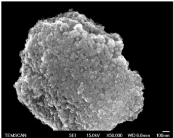
concen-tration is kept constant at 0.5 mol·L−1. The YSZ sol is stirred for 30 min, then dried in an oven at 50 °C until YSZ gel was obtained. After the dry-ing of the gel in supercritical conditions of 1-propanol, the aerogel was calcinated at 700 °C for 2 h. The morphology of this aerogel powder is shown inFig. 2.
As we can see, the aerogel powder exhibits a porous microstructure made of agglomerates of nanometric particles. The specific surface area of this mesoporous zirconia determined by BET method is close to 88 m2/g. This high state of division of the solid material brings a high
re-activity to this powder which is a key parameter and the feature used in thefirst step of the present investigation. For the further steps of this study, dense pellets and coatings were made from this aerogel powder. The second kind of materials is the YSZ pellets which were made by mixing the aerogel powder with a small amount of the precursor YSZ sol which is used as an“active” binder. A drying is realized at 80 °C in order to evaporate the major part of solvent and then the mixture is ground, cold pressed and sintered in air at 1100 °C for 2 h. A densification of about 92% was reached after heat-treatment.
Finally, the third kind of materials, used in this study, is the YSZ coatings. These coatings were deposited onto Ni-based superalloy substrates (Hastelloy X or AM1) covered with a NiAl or NiPtAl bond-coat. Samples werefirstly sandblasted with corundum 220 meshes followed by degreasing with acetone and ultrasonic cleaning in 1-propanol. YSZ top-coats were shaped by dip-coating technique. In order to realize thick coatings, the aerogel powder wasfirstly dis-persed in the previous YSZ sol (9.7 mol% YO1.5) at a ratio of 40%wt
in order to prepare the active precursor (sol loaded with powder). Then, superalloys were dipped into this composite sol and withdrawn at a controlled speed (250 mm/min). Several immersion/withdrawal cy-cles were performed until the expected thickness was reached. Finally, samples were heat-treated for 2 h at 1100 °C with appropriate heating and cooling rates. This coating process leads to porous and adherent YSZ ceramic layer as shown inFig. 3.
Then, the aerogel powder, pellets and coatings were heat-treated at 1100 °C for 2 h before CMAS exposure in order to obtain the convenient crystallized tetragonal phase of zirconia[10,11]. XRD patterns of the YSZ powder after calcinations at 700 °C and 1100 °C are presented inFig. 4.
The XRD pattern of the sample heat-treated at 1100 °C exhibits the characteristic peaks of the well-crystallized tetragonal zirconia without any other crystalline phase.
3.2. Preparation of the model CMAS sample
The chemical composition (33 CaO–9 MgO–13 AlO1.5–45 SiO2in
mol%) used to prepare a representative CMAS mixture is based on literature and reflects the average of deposit compositions found on ex-service turbine components operated in various environmental conditions, as reported by Borom et al.[12]and used by other authors
[4,13–15]. Other kinds of oxides could be found, in small quantities, in real deposits such as Fe2O3or NiO, coming from the upper stage of the
turbine, but they have not been taken into account in this study. The CMAS powder was obtained by mixing high purity powders of the indi-vidual oxides (CaO, MgO, Al2O3and SiO2) in appropriate proportions
with de-ionized water, then dried and heat-treated at 1400 °C for 1 h in a Pt crucible. A transparent and amorphous glass was obtained after quenching in water and it was ground intofine CMAS powder. XRD pat-tern is shown inFig. 5. The melting temperature of the synthetic CMAS was determined by DTA and it is about 1200 °C.
4. Experimental methodology and results
CMAS degradation of TBCs from Atmospheric Plasma-Spraying (APS) or Electron Beam-Physical Vapor Deposition (EB-PVD) has been widely reported in previous papers[4,5,7,16–18]. However, few or none have reported CMAS degradation of YSZ synthesized via sol–gel process. There-fore, it is interesting to investigate the deterioration of this kind of material whose microstructure is not oriented in opposition with the conventional processes.
Fig. 2. SEM-FEG micrograph of YSZ aerogel powder after 2 h heat-treatment at 700 °C.
Substrate
YSZ
Fig. 3. SEM cross-section of YSZ sol–gel coating.
t’-ZrO2
(a) (b)
Fig. 4. X-ray diffraction patterns of YSZ aerogel powder after 2 h at (a) 700 °C and (b) 1100 °C.
According to the procedure described inFig. 1, YSZ sol–gel powder, dense pellet and coatings were exposed to CMAS. In all the following tests, YSZ was placed under isothermal exposure to the model CMAS powder in a pre-heated furnace at the temperature of the test. 4.1. Interaction between YSZ aerogel powder and CMAS
An intimate mixing was made between YSZ aerogel powder and CMAS in a 1:1 weight ratio. This mixture was then heat-treated in a Pt crucible at temperatures ranging from 1100 °C to 1350 °C for 15 min to 2 h. The XRD patterns performed on the YSZ powder exposed to the model CMAS powder for 2 h at some selected temperatures in the same range are presented inFig. 6.
For tests performed at 1100 °C, we can notice the presence of diffrac-tion peaks corresponding to the CMAS recrystallizadiffrac-tion. On the other hand, for tests performed at 1250 °C or 1350 °C, no additional diffrac-tion peaks other than those of zirconia are present. However, the inter-action between YSZ aerogel powder and CMAS exhibits a tendency to peak transformation corresponding to a possible crystalline modi fica-tion. Rietveld refinement was performed on the sample exposed to CMAS for 2 h at 1350 °C. Result of this refinement is presented inFig. 7.
The presence of the diffraction peaks corresponding to the initial tetragonal YSZ as well as the monoclinic structure suggests that the tetragonal to monoclinic transformation has occurred during the in-teraction between YSZ aerogel powder and CMAS. It is now proved that CMAS induced a crystalline phase transformation of zirconia via a dissolution/re-precipitation mechanism[4,19,20]. YSZ particles in direct contact with silicates were dissolved into the molten CMAS. Once the solubility limit of zirconia is reached, yttria-depleted ZrO2
grains are able to re-precipitate. This depletion in yttria induces the de-stabilization of the tetragonal phase which leads to monoclinic transfor-mation upon cooling. The volume expansion caused by the tetragonal to monoclinic transformation generates high stresses and then can induce cracks in YSZ coatings[21]leading to the failure of TBCs systems.
4.2. Interaction between dense YSZ pellets and CMAS
The CMAS powder was deposited onto the surface of the samples (~10 mg/cm2). Tests were performed at 1100 °C, 1250 °C and 1350 °C
at durations varying from 5 min to 2 h. Fractures were realized on the pellets in order to evaluate the infiltration and the microstructural changes occurring within the dense ceramic, showing the interface be-havior between YSZ and CMAS (2D interaction).
All the samples exhibit very similar microstructures after high tem-peratures exposure to CMAS powder. The fracture surface of the YSZ pellets exposed to CMAS for 15 min at 1250 °C is shown inFig. 8. A lot of morphological changes occur in the YSZ pellet after CMAS interaction. The micrograph at higher magnification (Fig. 9) reveals that the frac-ture surface can be divided into three distinct zones.
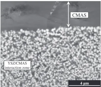
Thefirst, at the extreme surface (referred 1) which is in direct contact with CMAS deposit, consists of nanometric spherical and monodisperse zirconia particles as shown inFig. 10. The thickness of this mixed zone is around 20μm. This can be correlated to the dissolution/re-precipitation process which takes place when YSZ is put in interaction with molten CMAS.
Fig. 5. XRD pattern of the synthetic CMAS powder.
(c) (d) (b) (a) t’-ZrO2 m-ZrO2
CMAS recrystallization phases
Fig. 6. X-ray diffraction patterns at room temperature of YSZ aerogel powder after 2 h of exposure to CMAS for different temperatures: (a) 1100 °C, (b) 1250 °C, (c) 1350 °C and (d) YSZ aerogel powder heat-treated at 1350 °C for 2 h without CMAS powder.
m-ZrO2 t’-ZrO2
Fig. 7. Rietveld refinement of YSZ aerogel powder exposed to CMAS after 2 h at 1350 °C. Focus on the 26° - 34° angular domain showing monoclinic zirconia diffraction peaks.
The second zone (quoted 2) shows a significant decrease of porosity and microcavities are observed locally. This indicates that CMAS interac-tion can induce faster densification of the YSZ material and thus lead to a change in mechanical properties sufficient to cause degradations, such as cracks, in YSZ coatings[7]. The third zone exhibits the typical micro-structure of the aerogel powder used to realize the pellet, meaning that in this zone, powder has not been altered.
The fracture surface of the sample exposed to CMAS for 15 min at 1350 °C is shown inFig. 11. Higher test temperature reveals a great
increase of the interaction zone and a faster kinetics of infiltration but the mechanisms seem to be similar. The thickness extends up to ~ 160μm under pellet surface. However, this sample exhibits the same morphology than the previous one.
These results showed that CMAS can infiltrate a dense ceramic even after a short time of CMAS exposure. Temperature and time are critical parameters which can influence the degradation kinetics of YSZ materials.
4.3. Interactions between YSZ coatings and CMAS
The last step of this study was to compare the behavior of EBPVD and sol–gel coatings under CMAS exposure. EBPVD and sol–gel YSZ coatings were exposed to CMAS at high temperature. The silicate powder was deposited at the surface of the samples and tests were performed at 1250 °C for 1 h in each case.
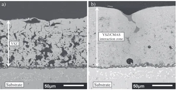
SEM cross-section of the unaffected sol–gel coating and after CMAS exposure is shown inFig. 12(a and b respectively).
100 µm Surface ~ 70 µm CMAS YSZ/CMAS interaction zone
Fig. 8. SEM micrograph of the fracture surface of YSZ sol–gel pellet exposed to CMAS at 1250 °C for 15 min. 1 3 2
50 µm
100 µm
Fig. 9. SEM micrographs of the fracture surface of YSZ sol–gel pellet exposed to CMAS at 1250 °C for 15 min.
4 µm
CMAS
YSZ/CMAS
interaction zone
Fig. 10. Polished cross-section showing zone 1 of the YSZ sol–gel pellet exposed to CMAS at 1250 °C for 15 min. 100 µm Surface ~ 170 µm CMAS YSZ/CMAS interaction zone
Fig. 11. SEM micrograph of the fracture surface of YSZ sol–gel pellet exposed to CMAS at 1350 °C for 15 min.
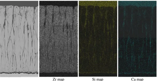
The entire coating seems to be fully densified after CMAS infiltration with a significant decrease of the coating porosity. Elemental mapping of the main chemical elements (Fig. 13) shows that CMAS infiltrated the whole coating thickness down to the TBC/TGO interface.
SEM micrographs at higher magnification (Fig. 14) revealed sig-nificant microstructural modification. The entire coating thickness is made of spherical particles of zirconia embedded in CMAS glass
and reflects that the dissolution/reprecipitation process occurred dur-ing the interaction.
The same experiment and characterization were carried out on EBPVD TBC. SEM cross-section of the unaffected EBPVD coating and after CMAS exposure is shown inFig. 15(a and b respectively).
The column tips showed an important microstructural degradation on thefirst 50 μm compared to the unaffected zone. The elemental
a)
b)
Substrate
Substrate
YSZ YSZ/CMAS interaction zone YSZ YSZ/CMAS interaction zoneFig. 12. SEM cross-section of YSZ sol–gel coating after 1 h at 1250 °C a) without CMAS and b) after CMAS exposure.
Zr map
a)
Y map
b)
Mg map
d)
Al map
e)
Ca map
c)
Si map
f)
100 µm
g)
YSZ/CMAS interaction zoneanalysis shows that CMAS reached, as previously indicated for sol–gel coating, to the bottom of the ceramic coating along the inter-columnar gaps (Fig. 16).
After 1 h at 1250 °C under CMAS exposure, dissolution/ reprecipitation mechanism and densification due to CMAS infiltration occurred for both coatings. Moreover, the excellent wetting properties on YSZ and their low viscosity[4]allow CMAS tofill the porosity of coatings.
Nevertheless, it is important to underline the significant difference between EBPVD and sol–gel coatings after interaction with CMAS. In-deed, the non-oriented porosity of sol–gel TBC leads to a uniform and homogeneous infiltration. The coating exhibits an important loss of porosity and acts as a dense layer (Fig. 12). By contrast, the columnar
microstructure of EBPVD TBCs leads to preferential infiltration path along the columns.
Thermomechanical degradation induced by CMAS infiltration has been widely studied on conventional TBCs[5–7,20,22–24]but, to the best of our knowledge, nothing has been reported so far in the case of sol–gel coatings. Further investigations will be done in order to under-stand the mechanisms of delamination for coatings with non-oriented microstructure.
5. Conclusion
The present study investigated the YSZ degradation induced by Calcium–Magnesium–Alumino Silicates following a step-by-step
50 µm 10 µm 2 µm YSZ/CMAS interaction zone
Substrate
a)
b)
c)
CMAS
ZrO
2particles
Fig. 14. SEM cross-section of YSZ coating exposed to CMAS at 1250 °C for 1 h (a) and higher magnifications of the CMAS/YSZ interaction zone (b and c).
50 µm
50 µm
b)
a)
methodology. This study highlighted that when CMAS interact with YSZ materials, they can induce several kinds of degradations. Thermochemical interactions via a dissolution/reprecipitation mecha-nism induce the destabilization of the initial tetragonal YSZ and impor-tant microstructural degradation. The comparison of YSZ EBPVD and sol–gel coatings under CMAS exposure revealed that the initial TBC microstructure plays a critical role in CMAS interaction. While EBPVD coatings lead to preferential path of infiltration along the columns, the non-oriented microstructure of sol–gel coating leads to a well-distributed infiltration. In this paper, we have exhibited for the first time the degra-dation of YSZ sol–gel materials by CMAS and have noticed the specific morphology of this“composite” material after interaction. In fact, benefits of the well-known high reactivity of sol–gel materials have been an important feature and will be a key point for further inves-tigation, particularly to develop CMAS-resistant coatings. Further-more, a next study will be dedicated to the understanding of the thermomechanical behavior of sol–gel TBCs under CMAS exposure. Acknowledgments
Authors would like to gratefully acknowledge French Defence Agen-cy (D.G.A.) and Safran (Snecma) for theirfinancial support and for pro-viding bond-coated superalloys substrates.
References
[1] R.A. Miller, J. Therm. Spray Technol. 6 (1997) 35. [2] D.R. Clarke, C.G. Levi, Annu. Rev. Mater. Res. 33 (2003) 383. [3] N.P. Padture, M. Gell, E.H. Jordan, Science 296 (2002) 280.
[4] S. Krämer, J. Yang, C.G. Levi, C.A. Johnson, J. Am. Ceram. Soc. 89 (2006) 3167. [5] C. Mercer, S. Faulhaber, A.G. Evans, R. Darolia, Acta Mater. 53 (2005) 1029. [6] C. Xi, Surf. Coat. Technol. 200 (2006) 3418.
[7] S. Krämer, S. Faulhaber, M. Chambers, D.R. Clarke, C.G. Levi, J.W. Hutchinson, A.G. Evans, Mater. Sci. Eng. 490 (2008) 26.
[8] C. Viazzi, J.P. Bonino, F. Ansart, Surf. Coat. Technol. 201 (2006) 3889.
[9] J. Fenech, M. Dalbin, A. Barnabe, J.P. Bonino, F. Ansart, Powder Technol. 208 (2011) 480.
[10] C. Viazzi, J.-P. Bonino, F. Ansart, A. Barnabé, J. Alloy. Compd. 452 (2008) 377. [11] J. Fenech, C. Viazzi, J.-P. Bonino, F. Ansart, A. Barnabé, Ceram. Int. 35 (2009) 3427. [12] M.P. Borom, C.A. Johnson, L.A. Peluso, Surf. Coat. Technol. 86-87 (1996) 116(Part 1). [13] K.M. Grant, S. Krämer, J.P.A. Löfvander, C.G. Levi, Surf. Coat. Technol. 202 (2007) 653. [14] P. Mohan, T. Patterson, B. Yao, Y. Sohn, J. Therm. Spray Technol. 19 (2009) 156. [15] R. Wellman, G. Whitman, J.R. Nicholls, Int. J. Refract. Met. Hard 28 (2010) 124. [16] J. Wu, H. Guo, Y. Gao, S. Gong, J. Eur. Ceram. Soc. 31 (2011) 1881.
[17] H. Peng, L. Wang, L. Guo, W. Miao, H. Guo, S. Gong, Prog. Nat. Sci. 22 (2012) 461. [18] M.H. Vidal-Setif, N. Chellah, C. Rio, C. Sanchez, O. Lavigne, Surf. Coat. Technol. 208
(2012) 39.
[19] A. Aygun, A.L. Vasiliev, N.P. Padture, X. Ma, Acta Mater. 55 (2007) 6734. [20] C.G. Levi, J.W. Hutchinson, M.-H. Vidal-Sétif, C.A. Johnson, MRS Bull. 37 (2012) 932. [21] E.H. Kisi, C.J. Howard, Key Eng. Mater. 153–154 (1998) 1.
[22] R.G. Wellman, J.R. Nicholls, Tribol. Int. 41 (2008) 657.
[23] J.M. Drexler, A. Aygun, D. Li, R. Vaßen, T. Steinke, N.P. Padture, Surf. Coat. Technol. 204 (2010) 2683.
[24] A.G. Evans, J.W. Hutchinson, Surf. Coat. Technol. 201 (2007) 7905. Fig. 16. Cross-sectional SEM micrograph of EBPVD TBC after CMAS exposure for 1 h at 1250 °C and corresponding elemental map.