HAL Id: tel-00273236
https://tel.archives-ouvertes.fr/tel-00273236
Submitted on 14 Apr 2008HAL is a multi-disciplinary open access archive for the deposit and dissemination of
sci-L’archive ouverte pluridisciplinaire HAL, est destinée au dépôt et à la diffusion de documents
modélisation à la normalisation MPEG-4
Marius Preda
To cite this version:
Marius Preda. Système d’animation d’objets virtuels : De la modélisation à la normalisation MPEG-4. Informatique [cs]. Université René Descartes - Paris V, 2002. Français. �tel-00273236�
UNIVERSITE RENE DESCARTES - PARIS V
Centre Universitaire des Saints-Pères
UFR DE MATHEMATIQUES ET INFORMATIQUE
Thèse présentée en vue de l’obtention du grade de Docteur
de l’Université RENE DESCARTES - Paris V
Discipline : Sciences de la Vie et de la Matière Spécialité : Mathématiques – Informatique
Par
Marius PREDA
Sujet de la Thèse :Soutenue le 19 décembre 2002, devant le jury composé de :
Monsieur le Professeur Georges STAMON Président Monsieur le Professeur Fernando PEREIRA Rapporteur Monsieur le Professeur Jean SEQUEIRA Rapporteur
Madame le Professeur Françoise PRÊTEUX Directeur de Thèse Monsieur le Docteur Gérard MOZELLE Examinateur
Acknowledgements
This work could not have been successfully carried out without the continuous help and support of many people during more than three years.
I would like first to express my deep thanks to Professor Françoise Prêteux, Head of the ARTEMIS Project Unit at INT, who has supervised this thesis. The quality of the training that I have benefited, the many advice and efficient help that she generously offered me all along these years, and the trust that she granted me by promoting me on the international scene, have been valuable assets for which I am deeply grateful and indebted to her.
I would like to express my respect and very special thanks to Professor Georges Stamon from Université Paris V-René Descartes, who has accepted to preside my Ph.D. Committee.
I express my gratitude to Professor Fernando Pereira from Instituto Superior Técnico who has co-reviewed my work. I warmly thank him for his numerous and relevant comments which have greatly contributed to improve the content of this manuscript.
I am also grateful to Professor Jean Sequeira, Head of the LXAO Group of the LSIS Department at Université de la Méditerranée, Aix-Marseille II, who has accepted to co-review this dissertation despite his multiple responsibilities. I am very happy to have the opportunity to meet him again. I express to Doctor Gérard Mozelle, Head of Digital Broadcasting Research and Standardization activities at Thomson, my deep thanks and respect for having generously shared with me his industrial expertise.
It is with a great interest and pleasure that I have shared the enriching adventure of standardization with my colleagues of the SNHC (Synthetic and Natural Hybrid Coding) Group of MPEG. Thanks to Alain Mignot, Michael Steliaros, Gauthier Lafruit, Alexandru Salomie, Francisco Moran-Burgos, Eric Delfosse, Mahnjin Han, James Kim, Patrick Gioia, et Mikael Bourges-Sevenier for their international support!
I also want to say to all Partners of the ViSiCAST European project how much I have appreciated our stimulating cooperation: many thanks to Mark Wells, Head of Televirtual, for a ever beautiful Visia; to Nick Tanton, Project Manager at BBC, for real-scale MPEG-4 Video experiments; and to Christoph Dosch and Werner Brückner from IRT for this great world première during the International Broadcast Convention when a MPEG-4 avatar-supported sign language broadcast transmission was achieved. In conjunction with this international influence, the ARTEMIS Project Unit has obviously acted as a favorable environment for the blossoming of my activities. I would like naturally to thank:
• Doctors Nicolas Rougon, Catalin Fetita et Titus Zaharia, Associate Professors at INT, for their complicity and conviviality,
• Mrs. Nicole Teste and Evelyne Taroni, for their administrative and friendly support, as well as for their good mood and humor,
• Doctor Marius Malciu, with whom I shared long summer or winter nights.
Since present and future rely on past, I can not forget to witness all my respect and gratefulness to Professor Vasile Buzuloiu from University POLITEHNICA of Bucarest, who has allowed me to lay solid foundations for this thesis.
Finally, I could not end this page without heartily thanking Andrea for her constant moral support and the infinite patience she has witnessed to me in all circumstances.
To Andrea
To my family
Contents
Contents ... 1
List of figures... 3
List of tables... 5
Abbreviations ... 7
0 Context and Objectives ... 1
1 Chapter One. Virtual Character Animation ... 7
1.1 Virtual Character Modelling ... 9
1.1.1 Polygonal meshes ____________________________________________________ 9 1.1.2 Parametric representations ____________________________________________ 10 1.1.3 Implicit representations _______________________________________________ 12 1.1.4 Building 3D virtual characters__________________________________________ 13 1.2 Virtual Character Animation ... 15
1.2.1 Kinematic approaches ________________________________________________ 17 1.2.2 Dynamic approaches _________________________________________________ 21 1.2.3 Motion-based approaches _____________________________________________ 21 1.2.3.1 Motion capture systems... 21
1.2.3.2 Motion editing systems ... 22
1.3 Conclusion ... 23
2 Chapter Two. MPEG-4 Face and Body Animation: Specifications, Implementation and
Performance Analysis ... 25
2.1 Overview of the MPEG-4 FBA specifications ... 27
2.2 Creating an FBA compliant avatar from a static 3D model ... 34
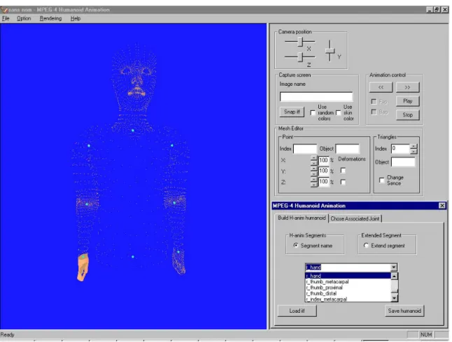
2.2.1 3D model segmentation _______________________________________________ 34 2.2.2 Virtual Human Modelling authoring tool _________________________________ 39 2.3 BAPs editor: the Artemis Animation Avatar Interface... 40
2.3.1 Key value-based animation ____________________________________________ 42 2.3.2 End-effector driven animation__________________________________________ 43 2.4 Performances analysis of the FBA framework in a client-server application... 45
2.4.1 Evaluation framework ________________________________________________ 45 2.4.2 Compression efficiency _______________________________________________ 48 2.4.3 Realistic animation___________________________________________________ 50 2.5 Conclusion ... 53
3 Chapter Three. Virtual Character Animation: the Skeleton, Muscle and Skin (SMS)
Framework... 55
3.1 Synthetic object deformation: toward a unified mathematical model... 57
3.2 Skeleton, Muscle and-Skin-based modelling and animation ... 58 3.2.1 Bone and muscle controllers for animating an articulated object_____________ 58 3.2.2 Bone-based modelling and animation ___________________________________ 60
3.2.3 Muscle-based modelling and animation__________________________________ 62
3.2.3.1 Muscle influence region ... 62
3.2.3.2 Muscle deformation and induced effects on the skin ... 63
3.3 Skeleton, Muscle and Skin nodes specification ... 66
3.3.1 SBBone Node _______________________________________________________ 66 3.3.2 SBMuscle Node______________________________________________________ 68 3.3.3 SBSegment Node ____________________________________________________ 70 3.3.4 SBSite Node ________________________________________________________ 70 3.3.5 SBSkinnedModel Node _______________________________________________ 71 3.4 Skeleton, Muscle, and Skin animation stream ... 73
3.4.1 Animation principle and resource representation__________________________ 73 3.4.2 Animation parameter representation ____________________________________ 73 3.4.3 Temporal frame interpolation __________________________________________ 74 3.4.4 Animation frame _____________________________________________________ 75 3.5 Experimental results... 76
3.6 SMS versus FBA ... 79
3.7 The SMS framework in the MPEG-4 Context ... 80
3.8 Summary ... 83
4 Chapter Four. MPEG-4 at Work: Sign Language Transmission over Digital Television
and Web-based Networks ... 85
4.1 Introducing sign language communication ... 86
4.2 Analysed solutions for sign language communication... 86
4.2.1 MPEG-4 video object-based encoding of a natural signer ___________________ 87 4.2.2 MPEG-4 Video object-based encoding of a virtual signer ___________________ 95 4.2.3 MPEG-4 Virtual Character Animation (FBA and BBA)_______________________ 96 4.2.4 Comparative evaluation _______________________________________________ 96 4.2.4.1 Equipment (hardware and software) required at the producer’s side ... 97
4.2.4.2 Real-time capabilities of producing the content ... 98
4.2.4.3 Reusability of the content... 98
4.2.4.4 Terminal capabilities ... 99
4.2.4.5 User interaction with the content... 100
4.2.4.6 Minimum bandwidth required for the transmission of the content ... 100
4.2.4.7 Comparison summary ... 114
4.2.5 Implementation in a real system: the ViSiCAST project ____________________ 116 4.3 Summary ... 117
5 Conclusions and future work ... 119
A.1 Appendix A. Related Publications ... 123
A.1.1 Book chapters______________________________________________________ 124 A.1.2 Journal papers _____________________________________________________ 124 A.1.3 Conference papers __________________________________________________ 124 A.1.4 Patents____________________________________________________________ 124 A.1.5 Tutorials __________________________________________________________ 125 A.1.6 Technical reports ISO________________________________________________ 125
A.2 Appendix B. XML compliant format for BBA ... 129
iii
List of figures
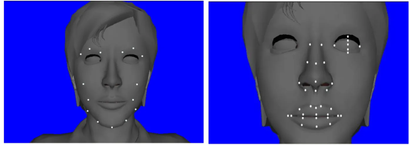
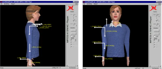
Figure 1.1. Different geometry complexity levels for virtual characters. _______________________________ 9 Figure 1.2. Single NURBS surface a) and b) and patched NURBS surfaces c) and d). ___________________ 11 Figure 1.3. Metaballs blending. _____________________________________________________________ 12 Figure 1.4. Metaball-based model: detail on human right arm designed by Roberto Campus [Campus]. ____ 13 Figure 1.5. Metaball-based model: detail on human heart [Mari]. __________________________________ 13 Figure 1.6. Full human body scanner. Courtesy of Cyberware. _____________________________________ 14 Figure 1.7. Virtual humanoid animation, for a segmented character (a) and b)), and for a seamless character (c) and d)).______________________________________________________________ 16 Figure 2.1. Examples of standardized key-points for the “face” object. ______________________________ 27 Figure 2.2. The Body scene graph hierarchy. __________________________________________________ 28 Figure 2.3. Standardized rotation planes for the avatar body. ______________________________________ 28 Figure 2.4. Abduction of the right arm. _______________________________________________________ 29 Figure 2.5. Flexion of the left arm. ___________________________________________________________ 30 Figure 2.6. Standardized rotation axes attached to shoulder, elbow and wrist._________________________ 31 Figure 2.7. Standardized rotation axes attached to fingers. ________________________________________ 31 Figure 2.8. Frame predictive-based method block diagram. _______________________________________ 32 Figure 2.9. DCT-based method block diagram. _________________________________________________ 32 Figure 2.10. Avatar initial position effects on the animation result. a) correct initial position, b) incorrect initial position, c) and d) results obtained from the same animation parameter set. __________________________ 33 Figure 2.11. a) Seamless body. b) FBA Body object: a hierarchical segmented character.________________ 34 Figure 2.12. Segmenting upper arm of the 3D model: selecting first JC. a) first point of the JC, b) second point of the JC, c) automatically generated segment between the two points, d) automatically generated JC. ___________________________ 36 Figure 2.13. Segmenting upper arm of the 3D model: selecting the second JC. a) first point of the JC, b) second point of the JC, c)
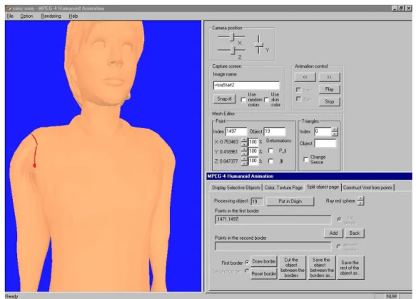
automatically generated segment between the two points, d) automatically generated JC. ________________ 37 Figure 2.14. Segmenting upper arm of the 3D model: geodesic dilation. a) two JC, b) random initialization between the two JC, c) geodesic dilatation, d) segmentation result.________ 38 Figure 2.15. Virtual Human Modelling Authoring Tool. The Segmentation Module control dialog._________ 39 Figure 2.16. Virtual Human Modelling Authoring Tool. The Building Module control dialog._____________ 40 Figure 2.17. The ARTEMIS Avatar Animation Interface with the forward kinematics BAP editing control dialog.
______________________________________________________________________________________ 41 Figure 2.18. The ARTEMIS Avatar Animation Interface used for interactive tracking of gestures in image sequences. ______________________________________________________________________________ 42 Figure 2.19. The ARTEMIS Avatar Animation Interface with the “Interpolation” control dialog for the case of two key-frames. __________________________________________________________________________ 43 Figure 2.20. Successive steps for Cyclic-Coordinate Descent algorithm for a two bones (arm-forearm) IK system.__________________________________________________________ 45 Figure 2.21. Animation parameters encoder and the UDP server interface. ___________________________ 46 Figure 2.22. The ARTEMIS Avatar Animation Interface with the “UDP client” control dialog. ___________ 46 Figure 2.23. “Applause” sequence: 2 avatars with different morphometries and animated with the same animation parameters. _________________________________________________ 47 Figure 2.24. Experimental results for sign “B”. Predictive (dense bullets) vs DCT BAP coding schemes. Distortion vs Q (I), Bit-rate vs Q (II) and Distorsion vs bit-rate (III). ________________________________ 49 Figure 2.25. Frame from animation data set. ___________________________________________________ 50 Figure 2.26. Finger animation: without BDTs (a), b), c), d)); with BDTs (a’), b’), c’), d’)) – BDTs
interpolation: key frames (a’) and d’)), interpolated BDTs (b’) and c’)). _____________________________ 52 Figure 3.1. Forearm bone influence volume. ___________________________________________________ 61 Figure 3.2. The muscle influence volume (in transparent green). ___________________________________ 63 Figure 3.3. Influence of the translation of a control point on the NURBS shape.. _______________________ 64 Figure 3.4. Influence of weighting a control point (here, B3) on the NURBS shape. _____________________ 65
Figure 3.7. The fields of the muscle node. _____________________________________________________ 69 Figure 3.8. The fields of the SBSkinnedModel node. _____________________________________________ 71 Figure 3.9. Principle of the analysor (illustration for one parameter). _______________________________ 78 Figure 3.10. Extract from the “MPEG-4 Requirements, version 15 (La Baule revision)”. ________________ 81 Figure 4.1. Natural signer: the “Florea” sequence.______________________________________________ 88 Figure 4.2. Binary segmentation mask (the signer - white - and the background - black) for the “Florea” sequence._______________________________________________________________________________ 89 Figure 4.3. Natural signer: the “Carlos” sequence. _____________________________________________ 90 Figure 4.4. Binary segmentation mask (the signer - white - and the background - black) for the “Carlos” sequence._______________________________________________________________________________ 91 Figure 4.5. The main steps of the head-and-hands segmentation procedure (“Florea” signer).____________ 92 Figure 4.6. The main steps of the head-and-hands segmentation procedure (“Carlos” signer).____________ 93 Figure 4.7. Binary mask for the NSV3O method for the “Carlos” sequence. __________________________ 94 Figure 4.8. Virtual character rendering: a) normal and b) modified (no lights and no textures) appearance model. _________________________________________________________________________________ 96 Figure 4.9. I, P, B structure of the Group of Planes (GOP). ______________________________________ 101 Figure 4.10. Bitrate [kbps] versus Q. ________________________________________________________ 103 Figure 4.11. Bitrate [kbps] versus frame-rate. _________________________________________________ 104 Figure 4.12. Bitrate [kbps] versus Q. ________________________________________________________ 106 Figure 4.13. Bitrate [kbps] versus frame-rate. _________________________________________________ 107 Figure 4.14. Bitrate [kbps] versus Q. ________________________________________________________ 109 Figure 4.15. Bitrate [kbps] versus frame-rate. _________________________________________________ 110 Figure 4.16. Multimedia Player.____________________________________________________________ 115 Figure 4.17. Synoptic description of a broadcast architecture ensuring sign language transmission into a standardized framework.__________________________________________________________________ 115 Figure 4.18. Snapshots of ViSiCAST broadcast system. __________________________________________ 116
v
List of tables
Table 2.1. Bit-rates for the frame predictive-based and DCT-based coding schemes. Results for signs "A" to "L". Q denotes the global quantization value. ______________________________________________________ 48 Table 2.2. Bit-rates [kbps] for the DCT-based coding scheme. Q denotes the global quantization value._____ 50 Table 3.1. Bit-rates [kbps] corresponding to frame predictive-based and DCT-based encoding schemes applied to "A" to "J" signs data. Q denotes the global quantization value. The frame-rate is set to 10 fps. ______________________________________________ 77 Table 3.2. Bit-rates [kbps] corresponding to frame predictive-based and DCT-based encoding schemes coupled with temporal interpolation, applied to "A" to "J" signs data. Q denotes the global quantization value. The frame-rate is set to 10 fps.__________________________________________________________________ 78 Table 3.3. Main FBA and SMS features._______________________________________________________ 79 Table 4.1. Scores with respect to the “Equipment required at the content producer’s side” criterion. _______ 98 Table 4.2. Scores with respect to the “real-time capabilities of producing the content” criterion. __________ 98 Table 4.3. Scores with respect to the “reusability of the content” criterion. ___________________________ 99 Table 4.4. Scores with respect to the “terminal capabilities” criterion. _____________________________ 100 Table 4.5. Scores with respect to the “user interaction with the content” criterion. ____________________ 100 Table 4.6. NSV: compression results with respect to the quantization step (example for “Florea” sequence”). ____________________________________________________________________ 102 Table 4.7. NSV: compression results with respect to the time sampling (example for “Florea” sequence”). ____________________________________________________________________ 103 Table 4.8. NSV: compression results with respect to the image resolution. ___________________________ 104 Table 4.9. NSV2O: compression results with respect to the quantization step. ________________________ 106 Table 4.10. NSV2O: compression results with respect to the time sampling. __________________________ 106 Table 4.11. NSV2O: compression results with respect to the image resolution.________________________ 107 Table 4.12. NSV3O: compression results with respect to the quantization step. _______________________ 109 Table 4.13. NSV3O: compression results with respect to the time sampling. __________________________ 109 Table 4.14. NSV3O: compression results with respect to the image resolution.________________________ 110 Table 4.15. Encoding overload for NSV3O+C. ________________________________________________ 111 Table 4.16. SSV: compression results with respect to the quantization step. __________________________ 113 Table 4.17. Scores with respect to the “required bandwidth” criterion. _____________________________ 114
vii
Abbreviations
3D Three Dimensional 3DMC 3D Mesh Coding
AC Alternative Components (in frequency representation) AFX Animation Framework eXtension
ASL American Sign Language BAP Body Animation Parameters BBA Bone based Animation BIFS Binary Format for Scenes BDP Body Definition Parameters BDT Body Deformation Tables CIF Common Intermediate Format CCD Cyclic Coordinate Descent
DC Direct Comonent (in frequency representation) DCT Discrete Cosinus Transform
FAP Face Animation Parameters FBA Face and Body Animation H Anim Humanoid Animation IP Internet Protocol
ISO International Standardization Organization MPEG Motion Picture Expert Group
MPEG-4 Multimedia Standard ISOIEC 14496 MPEG-2 Audio-Video Standard ISOIEC 13818 MPEG-2 TS MPEG-2 Transport Stream
NSV Natural Signer Video
NSViO Natural Signer Video with i Objects NURBS Non uniform rational B Splines QCIF Quarter Common Intermediate Format SMS Skeleton, Muscle and Skin
SNHC Synthetic and Natural Hybrid Coding SSV Synthetic Signer Video
VRML Virtual Reality Modeling Language XML eXtensible Markup Language XMT eXtensible MPEG 4 Textual Format
0 Context and Objectives
Context and Objectives
he current multimedia information society brings up new challenging issues in terms of production, distribution, and access of multimedia content. New forms of representation of the content are continuously developed and more and more content becomes available. In a society that cares about each of its members, new technologies can be used for example to address issues related to the distant communication and content access for the hearing impaired community.
We are presenting in this introduction the requirements of such multimedia framework, able to offer a solution to the deaf community using virtual characters. Then, we describe the advantages of providing such framework in terms of applications interoperability, support on the network and terminal devices level, data compression and synchronization, sharing and exchanging the content. These requirements make us review the existing integrated multimedia frameworks. Focusing on two open and international specifications, namely MPEG-4 and VRML, we analyse the performances and capabilities of each, related to their generic functionalities. We then present the structure of this dissertation.
We are currently witness to the explosion of multimedia content consumption. Broadcast productions overflow real life with images and sounds on thousand of channels throughout the world. Furthermore, a new age started with the development of the Internet. Nowadays, it is not only a source of written information, but a huge multimedia network where the distinction between user and content creator is not clearly stated.
The economic as well as social ramifications of this boom of the information technology society have been identified by the EC1. Recommendations have been written for the promotion of the
interoperability of multimedia application developments and their equal access to all citizens. This intent is specifically expressed when requesting that the multimedia content must be accessible also for people with audio-visual handicaps. Among them, the hearing impaired community is one of the early ones to benefit from these directives, especially where new technologies are concerned. As a communication means, this community developed, a gesture-based language called sign language. Offering them access to the content through their natural language means to provide with a translation between sound information and sign language. Taking for as example the digital television case, broadcasters now have an obligation to have at least 3% of their programs translated in sign language. To have a human translator on the set of every show would prove unrealistic in view of the rabid growth of the sector. Then, automated translation means between oral communication and sign language do need to be developed. To give full satisfaction such systems should not only translate but also be able to display a synthetic visual representation of the sign language. The majors difficulties are to be found in the linguistic complexity of both sign and oral languages, but also in the implementation of the gesture performing representation of a virtual human character.
Therefore, the system to be developed needs to cope with heavy constraints in terms of realistic animation of virtual characters, compatibility with networked environments (both broadcast and webcast), as well as compact representation for low bit rate transmission.
The complexity of the problems that the implementation of such system addresses let us think that such application should be considered in an integrated framework, where production, transmission and consumption of multimedia content are to be analysed. The objective of our research, is to propose a framework for virtual character animation with the following requirements:
• it should enable virtual character definition and animation,
• in order to ensure the visual confort in the case of sign language content, the static representation of the above-mentioned model should be realistic; i.e., the model should support geometries and textures as complex as required,
• in order to ensure the comprehension of the virtual character gesture, the animation of the above-mentioned models should be realistic; in particular, animating the model should not produce seams at the joints level and muscle-like deformations should be supported,
• the animation parameters should be easy to produce; the representation of the animation parameters should be consistent with respect to motion capture systems; editing tools for these parameters should be easy to build,
Context and Objectives
3 • the animation parameters representation should be compact and streamable, thus allowing
animation transmission on low bit-rate networks; furthermore, the stream should be easily multiplexed with other media streams already available,
• the animation speed should be appropriate in order to ensure the smoothness of the motion; with respect to sign language content, a frame-rate of 15 fps is the minimum acceptable, • the virtual character model should be able to co-exist, in a 3D scene with other kinds of media
such as video, sounds and 2D/3D graphic objects,
the animation should be synchronized with other playable media existent in the same scene, • the model definition and animation should be possible on low performance terminals, i.e.,
scalability to the terminal should be considered.
Creating, animating and sharing virtual characters require unified data formats. If some animation industry leaders try, and sometimes succeed [3DSM, Maya99], to impose their own formats in the computer (PC) world, the alternative of an open standard is the only valid solution when hardware products are to be build. A standard is all the more needed and awaited when applications and services require the support of various activity field actors such as content creators, developers, service providers (broadcasters, ISP), terminal manufacturers, or IPR holders.
The need for interoperability and the existence of open standards is concerning more and more legislative structures accros Europe.
The EU Framework Directive on Telecommunication Networks and Services [EC02-a] calls for interoperability of digital television services.
The European Council summit in Barcelona in March 2002 called for “…the Commission and Member States to foster the development of open platforms to provide freedom of choice to citizens for access to applications and services of the information society, notably through digital television...”. It went on to invite the Commission to present “a comprehensive analysis of remaining barriers to: the achievement of widespread access to new services and applications of the information society through open platforms in digital television…” [EC02-b].
The eEurope 2005 Action Plan states: “By supporting the emergence of alternative access platforms, such as digital television or 3 G mobile systems, the new action plan will further facilitate e-inclusion, also for people with special needs” [EC02-c].
Current works to provide 3D applications with a unified and interoperable framework are materialized by 3D graphics interchange standards such as VRML2 [VRML] and multimedia 2D/3D
standards such as MPEG-4 [ISO99]. Each one addresses, more or less in a coordinated way, the virtual character animation issue. In the VRML community, the H-Anim3 group released three versions of
their specifications (1.0, 1.1 and 2001), while the SNHC4 sub-group of MPEG5 released two versions:
MPEG-4 Version 1 allows face animation and MPEG-4 Version 2 allows body animation. In MPEG-4
2 VRML - Virtual Reality Markup Language 3 H-Anim – Humanoid AnimationWorking Group 4 SNHC - Synthetic and Natural Hybrid Coding 5 MPEG - Motion Picture Expert Group
the specifications dealing with the definition and animation of avatars are grouped under the name FBA6. The next section analyses the main similarities and differences of these two frameworks.
The VRML standard deals with a textual description of 3D objects and scenes. It focuses on the spatial representation of such objects, while the time behaviour is less supported. The major mechanism for supporting animation consists in defining it as an interpolation between key-frames.
The MPEG-4 standard, unlike the previous MPEG standards, does not only cope with highly efficient audio and video compression schemes, but also introduces the fundamental concept of media objects such as audio, visual, 2D/3D natural and synthetic objects to make up a multimedia scene. As established in July 1994, the MPEG-4 objectives are focused on supporting new ways (notably content-based) of communicating, accessing and manipulating digital audiovisual data [Pereira02]. Thus, temporal and/or spatial behaviour can be associated with an object. The main functionalities proposed by the standard address the compression of each type of media objects, hybrid encoding of the natural and synthetic objects, universal content accessibility over various networks and interactivity at the end-user. In order to specify the spatial and temporal localisation of an object in the scene, MPEG-4 defines a dedicated language called BIFS (Binary Format for Scenes). BIFS inherits from VRML the representation of the scene, described as a hierarchical graph, and some dedicated tools such as animation procedures based on interpolators, events routed to the nodes or sensor-based interactivity. However, BIFS introduces some new and advanced mechanisms such as compression schemes to encode the scene, streamed animations, integration of 2D objects and advanced time control.
In terms of functionalities related to virtual characters, both VRML and MPEG-4 standards define a set of nodes in the scene graph to allow for a representation of an avatar. However, only the MPEG-4 SNHC specifications deal with streamed avatar animations. A major difference is that an MPEG-4 compliant avatar can coexist in a hybrid environment and its animation can be synchronized with other types of media objects, while the H-Anim avatar can only exist in a VRML world and must be animated by VRML generic, usually non-compressed, animation tools.
With the large collection of tools it provides, the MPEG-4 standard can be the ideal candidate with respect to some of the requirements listed at the beginning of this section. As the MPEG-4 standard already has a framework dealing with the animation of human-like models, so-called FBA, we first propose to evaluate this framework. As some of the requirements are not fulfiled by the FBA, especially those related to realistic animation and representation of a generic model, we propose a new framework, so-called Skeleton, Muscle and Skin (SMS). The presentation of this work is structured in four chapters.
A comprehensive view of the evolution of 3D virtual character-related techniques is presented in Chapter 1. This brief overview is structured according to the two major components of an animation system, that is 1) modelling, and 2) animation. These components are strongly interconnected and application-dependent, as we will show afterwards. As our interest focuses on methods used in a production environment, special attention is paid to automatic methods to build and animate a virtual character. That is why the full-body geometry scanners and motion capture systems are also presented.
Context and Objectives
5 The second chapter describes the Face and Body Animation framework within the MPEG-4 standard in terms of specifications, tools implementation and performances analysis. The first section of the second chapter introduces the basic concepts used by the MPEG-4 standard to define a collection of multimedia objects and their relationships. In this general framework, the FBA specific mechanism for defining a virtual body in an MPEG-4 scene is presented. The FBA specifications do not mandate any specific method to obtain a real description of a 3D human body and its associated animation parameters. To address this first issue, we propose, a novel semi-automatic approach to get a MPEG-4 compliant body representation from a 3D mesh model of a human. This semi-automatic approach based on a segmentation algorithm is implemented as a part of the Virtual Human Modelling (VHM) authoring tool. In order to address the second issue, we present a dedicated authoring tool named the ARTEMIS Animation Avatar Interface (3AI), implemented to facilitate the editing and extraction of animation parameters. This authoring tool includes various interpolation schemes and one inverse kinematics method. The 3AI authoring tool also provides high-level functionalities like (1) composition of multimedia scenes made of natural data (images, video) and synthetic body representation and (2) calibration of a 3D body model according to anthropometrical characteristics. Then, we address a practical evaluation of both the compression and the animation performance of the FBA framework. Using the two above-mentioned authoring tools, an FBA compliant avatar and several animation data sets corresponding to the American Sign Language alphabet were created. A complete server-client communication system was then set up to test the complete application from the encoding of the animation parameters and their transmission over an IP (Webcast) and MPEG-2 (Broadcast) networks to their decoding and rendering of the associated human model. Results are presented and analysed in terms of trade off between the quality of the animation and the necessary bit-rate. These results underline performances and limitations of the FBA framework. In terms of applications, the original contribution described in this chapter consists in an end-to-end testing platform related to FBA content production, transmission and consumntion. In terms of methodology the original contributions are related to the FBA compliant content production, namely the geometry segmentation algorithm and the FBA animation parameters creation tools (interpolation, inverse kinematics).
The goal of the third chapter is to introduce a new framework for virtual character animation. The framework is built on a generic deformation model that we introduce in the first section. The model consists of a controller with a geometric support, a volume embedding the geometric support and a measure of the affectedness of the controller in the volume. With respect to these elements, we classify the main deformation tools reported in the literature. Then, we propose two declinations of the model which offer efficient control of the geometrical support and appropriate volume specification: bone and muscle controllers. We consider these tools as the core of the SMS framework and we show how they can be used to define and animate generic virtual characters. In order to represent generic virtual characters into a 3D scene, we provide the SMS architecture with the scene graph nodes. We then address the issue of efficient animation parameters representation by (1) enriching the framework with interpolation and inverse kinematics support and (2) proposing to adapt two compression methods (frame predictive-based and DCT-based). The results in terms of bit-rate, that we present and analyse, allow addressing animation on low bit-rate networked environment. A comparative study between the SMS and FBA frameworks, states the advantages of the SMS one. Finally, we describe how we have promoted the SMS framework into the MPEG-4 standard. The original contributions presented in this
chapter have to be considered in three classes. In terms of methodologie, a unified mathematical model of deformation mechanisms is proposed, and two instances of this model, the bones and muscle controllers are detailed. Within the second class, of applications, two compression methods for the animation parameters have been integrated. Finally, the SMS framework has been promoted to the MPEG-4 standard by providing it with a scene graph structure and a animation stream syntax compatible with the MPEG-4 structure.
There are several applications where synthetic data must coexist with natural data and moreover, the synchronisation is required. As previously mentioned, one of such application is the transmission of sign language related content over IP and MPEG-2 Transport Stream. This system is presented in Chapter 5. One of the requirements of this application is that the supplementary bandwidth needed for transmitting the sign language content must be less than 100 kbps for broadcast and less than 56 kbps for webcast. We will describe six possible solutions for sign language transmission over networks. The six solutions are classified with respect to the data format used to represent the content at different link of the chain: production, transmission and consuming. Thus, we decline video-based solutions, 3D-solutions and a hybrid (video and 3D) solution. With respect to some key-criteria we will analyse each solution, highlighting the specific advantages and limitations. By performing compression tests with each method, we will present and discuss the results with respect to the quality/bit-rate. The orinal contribution in this chapter consists in the analysis of several methods for transmitting sign language content by enphasising the advantages and limitations of each one with respect to the content production, transmission and consumntion.
1 Chapter One. Virtual Character Animation
Chapter One
Virtual Character Animation
he first 3D virtual human models were designed and animated with the help of computers in the 60’s. Since then, virtual character models have become more and more popular, so as to be available to growing numbers of users for all kinds of purposes. From simple and easy-to-control models used in video games [Activision, EArts], to more complex virtual assistants for commercial [Lat] or news web sites [Seonaid], or to the new stars of virtual cinema [WdPixar], television [Vandrea] or advertising [EveSolal], the 3D character models industry is now booming.
Furthermore, the steady improvements of the distributed network area in terms of bandwidth capabilities, bit rate performances or advanced communication protocols have lead to the
emergence of 3D communities [Blaxxun] and immersion experiences [Thalmann00] in distributed 3D virtual environments.
Hereafter, we present a comprehensive view of the evolution of 3D virtual character-related techniques. This brief overview is structured according to the two major components of an animation system, that is 1) modelling, and 2) animation. As our interest is on methods used in a production environment, special attention is paid to automatic methods for building and animating a virtual character. Full body geometry scanners and motion capture systems are presented and discussed.
Chapter One. Virtual Character Animation
9 1.1 Virtual Character Modelling
Virtual character modelling consists in specifying the geometry and appearance properties (colour, material, texture) of a synthetic model. According to the chosen type of synthetic model geometry, designing a virtual character can be done either using a segmented-based approach or within a seamless framework. The so-called segmented character is defined as a hierarchical collection of 3D objects, referred to as segments. The so-called seamless virtual character is geometrically defined as a single and continuous mesh. The most relevant techniques used to specify the model geometry refer to surface-based representations and more specifically to 1) polygonal meshes, 2) parametric equations, and 3) implicit representations.
1.1.1 Polygonal meshes
The polygonal surface-based technique consists of explicitly specifying the set of planar polygons which compose the 3D object surface, and connecting them together [Foley92]. Two types of information have to be kept about an object, namely, purely geometric information (coordinates of vertices) and topological information (which gives details on how the geometric entities relate to each others).
Historically, the polygonal surface-based technique is the first method introduced in computer graphics and remains the basic tool used at the rendering stage by all other surface representation techniques [OpenGL, Kovach]. Its main advantage lies in its capability to describe all complex surfaces, with smoothness conditioned by the number of polygons used. Figure 1.1 shows an example of two characters with different geometry complexities.
a) b) Figure 1.1. Different geometry complexity levels for virtual characters.
However, in a real-time animation framework, increasing the number of polygons of a virtual model may significantly deteriorate the animation’s performances. In this case, the adopted solution consists in deriving a lower resolution version of the virtual character, then animating/deforming this version, and eventually recovering the full-resolution version using a subdivision surface method [Catmull78, Loop87, Zorin00].
1.1.2 Parametric representations
Non-planar parametric representations of a surface are widely used in computer graphics because of the easy computation and simple mathematical manipulation. A non-planar surface patch, i.e. an elementary curved surface entity, is defined as the surface traced out with the two parameters (u,v)∈[0,1]2, in a two-parameters representation:
( )
u,v[
x( ) ( ) ( )
u,v,y u,v,z u,v]
.P = (1.1)
According to the curve degree, the patch surface can be of a linear, cardinal, B-spline or Bézier type [Farin]. The patch-based modelling method aims to produce patches trailing the curve profile(s) and to stitch them together in order to build complex surfaces. Specific constraints have to be introduced in order to properly build a patch-based virtual character. Special care is recommended to (1) completely cover a joint with a unique patch surface, and (2) ensure the continuity of the mesh at the patch borders where adjacent frontiers should be identically deformed. Mathematically, the patch-based surface representation is the limit surface obtained through convergence of an iterative surface subdivision procedure.
NURBS-based surface representation [Piegl97] is an extension of the B-spline patch obtained by weighting the influence of each control point. A NURBS surface of degree (p,q) is defined as:
( )
( )
( )
( )
( )
,
,
0 0 , , , 0 0 , , , ,∑∑
∑∑
= = = =⋅
⋅
⋅
⋅
=
m i n j ip jq i j m i n j ip jq i j ijw
v
N
u
N
P
w
v
N
u
N
v
u
P
(1.2)where
N
i,j denotes the B-spline basis functions,P
i,j the control points, andw
i,j the weight ofj i
P
, . In this case, a non-uniform weighting mechanism increases the flexibility of the representation, which then becomes appropriate to model a wide range of shapes with very different curvature characteristics, while the number of control points is kept to a minimum.As an example of the ability of NURBS-based representation to model complex shapes, Figure 1.2 a) and b) shows a head model represented by using a single NURBS surface. However, the number of control points involved in this type of representation may be important, which raises several limitations for real-time animation. Decreasing the number of control points requires to model a 3D object by patching several NURBS surfaces as illustrates Figure 1.2 c) and d).
Chapter One. Virtual Character Animation
11
a) b)
c) d) Figure 1.2. Single NURBS surface a) and b) and patched NURBS surfaces c) and d).
1.1.3 Implicit representations
The implicit representation of the geometry of a 3D object is a modelling technique using the so-called metaballs [Blinn82, Wyvill86], also known as blobby objects. A metaball can be viewed as a particle surrounded by a density field. The density assigned to the particle (its influence) decreases with the distance. An implicit model is inferred by considering an isosurface through this density field - the higher the isosurface value, the nearer it will be to the particle. The key to using metaballs is the equation specifying the influence of an arbitrary particle on an arbitrary point in space. Blinn [Blinn82] used exponentially decaying fields for each particle:
)
exp(
*
)
(
r
b
ar
C
=
−
, (1.3)while Wyvill et al. [Wyvill86] defined a cubic polynomial based on the radius of influence R of a particle and the distance r from the centre of the particle to the field location considered:
1
2
2
)
(
2 2 3 3+
−
=
R
r
R
r
r
C
. (1.4)The powerful aspect of metaballs lies in the way they can be combined. By simply summing the influences of each metaball at a given point, we get a very smooth blending of the spherical influence fields (Figure 1.3) thus allowing for a realistic, organic-looking shape representation.
a) b) c) Figure 1.3. Metaballs blending.
By combining metaballs-based surfaces, the designer can achieve high quality representations of real anatomical structures as shown in Figure 1.4 for an example of a human right arm and in Figure 1.5 for a human heart. However, because the control of implicit surfaces is ensured by the equation coefficients, intuitive animation of such surfaces is hard to achieve. While the global effects as scaling are easy to perform, local deformations are usually obtained by a combination of locally-defined implicit functions. Furthermore, mapping textures on such geometry is a difficult task. Usually, the models designed with this technique have their colours specified at the vertex level or are covered by plain colours.
Chapter One. Virtual Character Animation
13
Figure 1.4. Metaball-based model: detail on human right arm designed by Roberto Campus
[Campus].
Figure 1.5. Metaball-based model: detail on human heart [Mari].
In practice, the choice of one of the above three approaches for 3D object representation depends on the targeted application and is a trade-off between speed requirements for real-time animation and quality of the object rendering. For example, a character involved in a computer gaming environment is usually modelled with simple polygons, while in the case of a movie, characters can be either modelled as complex polygonal surfaces using subdivision surface techniques or directly defined as NURBS surfaces. Conversely, virtual character animation by means of implicit surfaces remains difficult because of the complexity of manipulating the control coefficients to obtain authoring free-style animation. In addition, a real-time rendering is hard to achieve due to the time-consuming rasterisation process required for complex objects. The use of metaballs is thus limited to off-line productions such as in the movie industry [WD97].
From the previous remarks, we are focusing in our research on meshed models and we present in the following the basic approaches used in practice for building a virtual character.
1.1.4 Building 3D virtual characters
Two different courses can be chosen from in order to build a virtual character according to the researched appearance of the virtual character (cartoon-like or realistic), and depending on the technology available to the designer.
On the one hand, the designer can build interactively the model’s anatomical segments and set up the model hierarchy. Several authoring tools and geometry generating mechanisms make it possible to model a virtual character in a relatively short time [3DSM, Maya]. The main drawback of this method is that the result is strongly dependent on the designer’s artistic skills and experience. In addition, this procedure is tedious and time-consuming.
On the other hand, a faster and proven method is the use of 3D scanners. Contrary to Computer Aided Manufacturing, the aim of 3D scanning is to create an electronic representation of an existing object, capturing its shape, colour, reflectance or other visual properties. In its principle,
3D scanning is similar to a number of other important technologies (like photocopying and video) that quickly, accurately and cheaply record useful aspects of physical reality.
The scanning process can be structured according to the following steps: acquisition, alignment, fusion, decimation and texturing. The first step aims at capturing the geometric data of the 3D object by using a dedicated scanning device (Figure 1.6). Depending on the type of scanner used, the execution of this phase can vary considerably. Either a single scanning is enough to capture the whole object, or series of partial scans (called range maps) are needed, each of them covering a part of the object. In the latter case, range maps taken from different viewpoints have to be aligned, which is the task of the second step. This procedure can be completely automatic if the exact position of the scanner during each acquisition is known. Otherwise, a manual operation is needed to input the initial placement, then the alignment is performed automatically. Once aligned, the partial scans need to be merged into a single 3D model (“fusion” step).
Figure 1.6. Full human body scanner. Courtesy of Cyberware.
Because 3D scanners provide a huge amount of data, a “decimation” step is required. For an effective use of the model, one has to reduce the size of the acquired geometric information, especially of the less significant parts of the object (a sample rate of 0.25 mm can be useful for very complex sections, but not on flat surfaces). Decimation software can be based on edge collapsing [Ronfard96] and error-driven simplification [Schroeder92].
The last step, “texturing”, is not mandatory for applications such as simulations in a virtual environment but, for a large array of objects, additional information about the real appearance of the object must be provided. This is usually achieved by texturing the final model, using pictures taken during acquisition. The pictures are first aligned to the geometry (manually or automatically) and then mapped to the model.
Chapter One. Virtual Character Animation
15
Once the virtual character has been created, one should be able to change its postures in order to obtain the desired animation effect. The following section addresses the problem of virtual character animation and presents the main approaches reported in the literature.
1.2 Virtual Character Animation
Virtual character animation is directly related to the model type used in generating the character, that is, segmented or seamless. Indeed, in the first case, the model is defined as a hierarchical collection of segments, while in the second case, it is composed of a single mesh. These particularities have to be taken into account in the developed animation approaches.
Animating a segmented character consists in applying affine transformations to each segment. The main advantages of such a simple technique are real-time capabilities on basic hardware configurations and intuitive motion control. However, such an animation procedure results in seams at the joint between two segments (Figure 1.7 a) and b)). This undesirable effect, in the case of cartoon-like animations, can be more or less side-stepped using ad hoc methods, such as introducing spheres at the joint level or 3D objects to mask the joints. However, more realistic animations require handling local deformations.
Animating a seamless character consists in applying deformations at the skin level. The major 3D mesh deformation approaches can be classified into the following 5 categories:
• Lattice-based [Maestri99]. A lattice is a set of control points, forming a 3D grid, that the user modifies in order to control a 3D deformation. Points falling inside the grid are mapped from the unmodified lattice to the modified one using smooth interpolation. • Cluster-based [Maestri99]. Grouping some vertices of the skin into clusters enables to
control their displacements by using the same parameters.
• Spline-based [Bartels87]. Spline and, in general, curve-based deformations allow deforming a mesh with respect to the deformation of the curve.
• Morphing-based [Blanz99]. The morphing technique consists in smoothly changing a shape into another one. Let us mention that such a technique is very popular for animating virtual human faces from pre-recorded face expressions.
• Skeleton-based. [Lander99]. The skeleton is a hierarchical structure and the deformation properties can be defined for each element of this structure.
The first four categories are used in animating specific objects as eyes (lattice), and face expressions (morphing), and are more or less supported by the main animation software packages. The last category, more and more encountered in virtual character animation systems, introduces the concept of skeleton.
The skeleton of a virtual character is a set of semantic information (usually, the skeleton is not displayed) composed in a hierarchical structure of elementary entities called bones. The seamless character is deformed by applying rigid transformations onto the skeleton bones. These transformations induce displacements of a subset of the skin vertices. This technique avoids seams
at joint level (Figure 1.7. c) and d)). The skeleton-based animation concept will be described in detail in Chapter 3.
a) b)
c) d) Figure 1.7. Virtual humanoid animation, for a segmented character (a) and b)),
and for a seamless character (c) and d)).
To design the virtual character skeleton, an initialisation stage is necessary: the designer has to specify the influence region of each bone of the skeleton as well as a measure of influence. This stage is mostly interactive and recursively repeated until the desired animation effects are reached. Deforming a seamless character remains a complex and time-consuming task, requiring dedicated hardware. However, the increasing achievements in computer graphics hardware contribute to promote the skeleton-based animation technique as a “standard” in 3D applications [3DSM99, Maya99, Kalra98]. The current trend is in favour of dividing the virtual character into seamless sub-parts and to deform each one independently of the others. This strategy helps to fulfil the
real-Chapter One. Virtual Character Animation
17
time requirements and to unify the animation approaches for segmented and seamless virtual characters.
In this respect, three main approaches for skeleton-based virtual character animation can be distinguished in the literature, namely kinematic, dynamic and motion-based. They are presented in the following sections.
1.2.1 Kinematic approaches
The kinematic approaches take into account critical parameters related to the virtual character properties such as position (orientation) and velocity.
In kinematic manipulation techniques, one of the working solutions is to directly control the relative geometric transformation of each bone of the skeleton. This approach, also called Forward Kinematics (FK), is a very useful tool for the designer [Watt92] to manipulate the postures of virtual characters. In this method, critical parameters correspond to the geometric transformation applied to each bone of the skeleton.
An alternative approach is to fix the location in the world coordinates for a specific level of the skeleton, so-called end-effector (e.g. the hand for a human avatar), and to adjust accordingly the geometric transformation of its parents in the skeleton. With this method, also called Inverse Kinematics (IK), the critical parameters correspond to the geometric location of the end-effector.
Considering a skeleton-based virtual character, its posture is given by a set of parameters including the position and the orientation of each bone in the space. These parameters, associated with the set of joints (bones articulations) in the skeleton, form the so-called state vector of the skeleton.
Given a subset of interconnected joints in a virtual character skeleton and its associated state vector q, the forward kinematics approach consists in specifying q over the time. In this way, at each moment, the state of a bone in the chain can be computed. The state x (position and orientation, x=(Px,Py,Pz,Ox,Oy,Oz)T) of the end-effector is then expressed as a function of the state vector q:
)
(q
f
x
=
. (1.5)The inverse kinematics issue consists in finding the joint state vector
q
if the end-effector is in a specific position and orientation, x:)
(
1
x
f
q
=
− . (1.6)Using IK to change the posture of a virtual character has the following advantages:
• for the designer, it represents a powerful manipulation tool, reducing the time to set key postures;
• with respect to the animation transmission, the set of target position of the end-effector is more compact than the geometric transformations for all the components of the link.
As solving the IK problem consists in solving a non-linear equations system, in most cases being a redundant system, the task is not easy and the solution is not unique. The various methods reported in the literature can be categorised into analytical and iterative methods. However, methods combining the two approaches have been reported for solving the IK problem in the case of a human-like arm and leg [Tolani00]. An overview of the major approaches is presented hereunder:
i) Analytical method. When the number of joints is reduced, the non-linear equation system can be directly solved. The method has first been proposed in robotics [Paul81, Craig89] and then adopted in computer graphics [Korein85, Tolani00]. Its limitation lies in the fact that for a particular articulated structure, there may be no analytical solution.
ii) Iterative methods. Inspired by the Newton-Raphson method for the resolution of non-linear equations [Ortega70], the non-linearization around an initial configuration has been proposed [Whitney69]. Iterative methods solve the inverse kinematics problem by using a sequence of steps leading by increment to a better solution for the joint angles. The goal is to minimize the difference between the current and the desired position of the end-effector. In this category, the most developed approaches rely on Jacobian matrix as well as on optimization and minimization methods. On the one hand, pseudo-inverse and transpose of Jacobian have been investigated. On the other hand, gradient-based, genetic algorithm and cyclic coordinate descend approaches have been proposed. Let us present each method and comment on their advantages and limitations.
i) Jacobian inverse
The Jacobian J is the multidimensional extension of the single variable differentiation [Watt92]. There is a relationship between the Cartesian space of the end-effector x and the joint space of the joint angles
q
: the Jacobian transforms the differential angle variations to differential motions of the end-effector [McKerrow91]:q
q
J
x
&
=
(
)
&
. (1.7)The vector x&contains the linear and rotational velocity components of the end-effector
T z y x z y x dP dP dO dO dO dP
x&=( , , , , , ) and
q&
represents the time derivative of the state vector (rotational velocity for each joint). In order to obtainq&
, the following operation should be performed:x
q
J
q
&
=
−1(
)
&
. (1.8)In a simple representation, the Jacobian columns (a column corresponds to one joint) are the partial derivative of the end-effector with respect to each joint as follows:
Chapter One. Virtual Character Animation 19 ∂ ∂ ∂ ∂ ∂ ∂ ∂ ∂ ∂ ∂ ∂ ∂ = = i z i y i x i z i y i x i n q O q O q O q P q P q P J where J J J J / / / / / / ], ... [ 1 2 . (1.9)
Performance measures for various methods applied to obtain the Jacobian can be found in [Orin84]. In order to solve Equation (1.8), the inverse of the Jacobian is required. [Maciejewski90] outlined the following problems when inverting the Jacobian: (1) usually the Jacobian is not square, (2) singularities may occur (Jacobian determinant equals 0), and (3) an infinite number of solutions for the same end-effector configuration are possible (the Jacobian is degenerated). In the first case, the Jacobian pseudoinverse provides the best approximation which gives a least squares solution of minimum norm. [Golub65] defined the pseudoinverse using Singular Value Decompostion (SVD). Other methods to define the pseudoinverse can be found in [Rao71]’s comprehensive book. The singularity problem has been solved by [Nakamura86] using the so-called "singularity robust inverse".
ii) Jacobian transpose
To overcome the computation cost of Jacobian inverse, [Wolovich84, Welmen93 and Siciliano96] propose to use the transpose of the Jacobian instead of its inverse. The idea is based on the principle of virtual works and generalised forces [Paul81]. The virtual work can be enunciated respectively
- as the product between the force
F
acting on the end-effector and the distance it is displaced,- or as the product between angular displacement of a joint and the torque
τ
affecting the joint:q
x
F
&
=
τ
&
. (1.10)By transposing (1.10) and substituting
x
&
=
J
(
q
)
q
&
, we obtain:F
J
T=
τ
. (1.11)Equation (1.11) is used to define a new control law to find an iterative solution of Equation (1.5):
)
(
)
(
q
K
x
x
J
q
=
T d−
&
, (1.12)where
x
d−
x
is the error, i.e. the difference between the desired positionx
dand the current position x.K
is a positive defined weight matrix. The advantages of the described algorithm are that no numerical singularity is met, since only forward kinematics is used, and the algorithm is computationally efficient in comparison to anumerical inversion of the Jacobian. However, because of its poor convergence properties, especially near a solution, the number of steps required to reach the solution may be much higher than with pseudoinverse-based techniques.
iii) Optimization and Minimization Methods
Optimization is a well-known field in numerical mathematics, widely reported in the literature [Walsh75]. In the framework of IK, the difference between the goal position of the end-effector and its current state, expressed as a function of joints, can be considered as the measure to be minimized:
2
))
(
(
)
(
q
P
x
q
E
=
−
. (1.13)In the computer graphics field, [Zhao89] and [Zhao94] report the use of an optimization method, [Goldfarb 69], for the manipulation of an articulated figure: a non-linear function (describing the degree of satisfaction of all constraints) is minimized under a set of linear equality and inequality constraints describing joint limits. This method is applied to manipulate a human-like articulated figure [Phillips90]. Genetic algorithms have recently been used to tackle general optimization problems, and they have also been applied to inverse kinematics [Khwaja98]. Generally, genetic programming-based methods are very slow and finding an adequate solution cannot be guaranteed (in a reasonable time). However, this method is useful for more complex and independent motion controls as well as animations (e.g. walk, jump).
iv) Cyclic Coordinate Descent
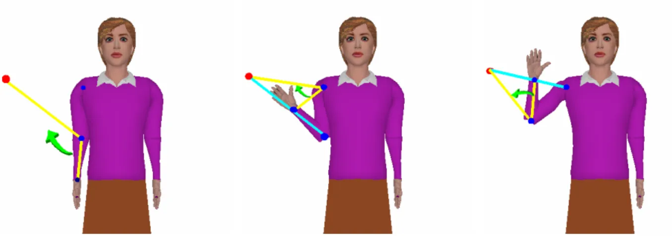
The Cyclic Coordinate Descent (CCD) method is a special case in the family of minimization methods. Its principle consists in applying the E(q) minimization (1.13) to each joint separately [Eberly01, Welman93], in successive order, from the most distant segment to the base segment. The difference between this method and the previous one is that only one joint variable is modified at each step. Following the fact that only one joint variable is changing along the minimization process, an analytic solution could be used. The interesting features of the CCD method are that there is no need for matrix inversion and it is free of singularities. In most cases, only a few iterations are enough to achieve a sufficient precision and therefore this method could be used in real-time applications.
The relatively small number of parameters used with the IK approach makes it an appropriate technique to be considered when a low bit-rate animation is targeted. We will address this issue in Chapter 2 by evaluating an IK method operating with the standardized FBA animation parameter set and in Chapter 3 by including in the generic developed framework (node definition and animation parameters) the IK-related information.