Titre:
Title
: Perspectives on EM metamaterials
Auteurs:
Authors
: Christophe Caloz
Date: 2009
Type:
Article de revue / Journal article
Référence:
Citation
:
Caloz, C. (2009). Perspectives on EM metamaterials. Materials Today, 12(3), p.
12-20. doi:
10.1016/s1369-7021(09)70071-9
Document en libre accès dans PolyPublie
Open Access document in PolyPublie
URL de PolyPublie:
PolyPublie URL:
https://publications.polymtl.ca/3392/
Version: Version officielle de l'éditeur / Published version
Révisé par les pairs / Refereed
Conditions d’utilisation:
Terms of Use
:
CC BY-NC-ND
Document publié chez l’éditeur officiel
Document issued by the official publisher
Titre de la revue:
Journal Title:
Materials Today (vol. 12, no 3)
Maison d’édition:
Publisher:
Elsevier
URL officiel:
Official URL:
https://doi.org/10.1016/s1369-7021(09)70071-9
Mention légale:
Legal notice:
Ce fichier a été téléchargé à partir de PolyPublie, le dépôt institutionnel de Polytechnique Montréal
This file has been downloaded from PolyPublie, the institutional repository of Polytechnique Montréal
metamaterials
Over the past decade, electromagnetic metamaterials have become an extremely active field of research in both the physics and the engineering communities1-5. At the time of writing,
hundreds of papers on metamaterials are being published every month, and for non-specialists the rapid evolution of this field might be hard to gauge. In this context, some critical perspectives may be found useful. This paper is intended to present such a perspective. It is not meant to be either exhaustive or definitive, but only reflects some of the author’s thoughts, with emphasis on fundamental concepts and practical applications.
Metamaterials are commonly defined as artificial effective electromagnetic structures with unusual properties not readily found in nature. In this definition, the term “effective” means that the size p of the structure’s unit cell, or period, is much smaller than the guided wavelength λg of the propagating wave (p<<λg), so the fields are averaged across the unit cells and really “see” the structure as a
homogenous medium at a macroscopic scale6. The term “unusual”
is relative. In its broad sense, metamaterials should include artificial dielectrics7-9, since they constitute sub-wavelength unit cell structures. However, “unusual” is generally meant to imply material properties which have been hardly explored before the turn of the 21st century, in particular negative refractive index (NRI), first explicitly theorized by Veselago back in 196710 after some precursors11-14 but experimentally demonstrated, following Pendry’s works on artificial electrically and magnetically negative artificial dielectrics15,16, only in 200117.
Unfortunately, initial metamaterial structures15-17 revealed unfavorable characteristics rendering them unsuitable for most practical applications: narrow bandwidth due to their resonant nature, and bulky size due to their volumetric configuration. The breakthrough came in June 2002 with the discovery of non-resonant transmission line (TL) NRI metamaterials by Caloz and Itoh18,19, Iyer and Eleftheriades20,
and Oliner21, which quickly led to a large number of novel microwave
Electromagnetic (EM) metamaterials have become a field of intense
research activities. This paper presents a critical perspective of
the field, with emphasis on fundamental concepts and practical
applications. Metamaterials are explained in the general context of
periodic structures. Resonant particle type and transmission line
type metamaterials are compared, and their fundamental connection
is established. Exotic phenomena recently reported and associated
challenges are briefly reviewed. Practical applications are enumerated
and illustrated by an example. The paper concludes with an optimistic
outlook regarding the future of metamaterials.
Christophe Caloz
École Polytechnique de Montréal, Pavillon Lassonde, Poly-Grames Research Center, Montréal, H3T 1J4, Québec, Canada E-mail: [email protected]
Perspectives on EM metamaterials REVIEW
MARCH 2009 | VOLUME 12 | NUMBER 3 1 3 applications1-4. These concepts were also transposed by Engheta
and Alù to the optics using plasmonic22 nano-particules23,24. This paper reviews these applications along with more recent ones. Unfortunately, there has been a dichotomy between resonant particle metamaterials and TL metamaterials over the past few years: the former are sometimes insufficiently understood in the engineering community, while the latter have been as invisible as being drapped by a cloak in the physics community! It is one of the objectives of this paper to show the close connection existing between the two types of metamaterials. Moreover, there have been some misconceptions about metamaterials in the engineering community25,26,27, which, at the other end of the physicists’ spectrum, sometimes restrictively apprehend metamaterials as circuit-type filter structures28,29. Some of these misconceptions have been clarified, but others subsist, as for instance the treatment of periodic structures as effective media26,27. This paper also attempts to clarify some of these issues.
Nowadays, metamaterials represent concepts and structures encompassing a range of artificial properties that extends well beyond just NRI, including all possible types of material parameter responses, such as single negative parameters, less-than-one refractive index, graded index for transformation optics, bi-anisotropy, engineerable dispersion and nonlinearity for analog processing, and many others to come, which will likely be enabled by emerging nanotechnologies30.
Finally, some promising directions are also discussed.
What is the refractive index of a
metamaterial ?
Periodic structures31, such as photonic crystals32-34, are not effective structures when operated at frequencies in the Bragg regime, where the period is comparable to (or larger than) the guided wavelength (p ≈ λg). In this regime, the structure is diffractive rather than refractive, and it cannot be characterized in terms of a single refractive index. Therefore, periodic structures in the Bragg regime do not fall in the category of metamaterials according to the definition given in the introduction, even though they can emulate effects similar to negative refraction34-36. Nevertheless, NRI metamaterials, not readily existing in nature, are generally made of periodic arrangements and satisfy the effective medium condition p<<λg only over a restricted frequency bandwidth. It is therefore instructive to consider them in the general context of periodic structures for a complete analysis and a proper understanding of their behavior. For the sake of simplicity, we will restrict the discussion to isotropic structures in this section.
Metamaterials can be 1D, 2D or 3D. Although it may be argued that a 1D structure does not constitute a material in the form of matter, a 1D metamaterial “structure” exhibits all the fundamental properties of its 2D and 3D counterparts, similar in effect to the 1D conventional periodic structures exhibiting most of the fundamental properties of their 2D and 3D counterparts (diffraction, band diagram, Bloch-Floquet harmonic spectrum, defect modes, surface waves). The comparable
behavior of 1D metamaterials to their 2D and 3D counterparts is even more substantial since the response of effective media does not depend on its lattice type (e.g. simple cubic, body-centered cubic, or face-centered cubic, 14 types in 3D37) but only on the nature of its
“atoms”38. Therefore, we may consider a 1D structure to reveal the
true nature of the refractive index of a metamaterial.
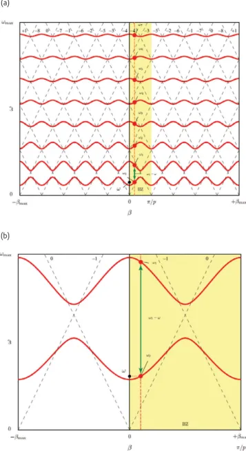
The dispersion diagram of a typical (conventional) 1D periodic structure (e.g. a periodically loaded waveguide), with its infinite set of
Fig. 1 Typical dispersion diagram of a 1D periodic structure, with the unperturbed space harmonics in dashed lines and the actual band structure in solid lines, where ω represents the operation frequency. (a) Case of a relatively large electromagnetic period p. (b) Case of a 5 times smaller period. The space harmonics indexes (q) are shown horizontally at the tops, while the band indexes (m) are indicated horizontally near the centers. The two graphs have the same full ranges.
(b) (a)
positive and negative group velocity space harmonics (Bloch-Floquet theorem)
( )
0( )
2 , ( ) q q q p π β ω = ±⎡⎢β ω + ⎤⎥ ∈ ⎣ ⎦ N (1)is shown in Fig. 1 for two different periods p. We will show that if the condition p<<λg is satisfied, the influence of the higher space harmonics (|q| > 0) is negligible, so that an effective refractive index may be defined in terms of the fundamental space harmonic of the structure as
( )
0( )
0( )
0 c n k β ω β ω ω ω = = , (2)where the positive sign has been chosen to ensure positive group velocity νg = ∂ω/∂β = ∂ω/∂β0(ω). For the sake of the argument, consider the Sturm-Liouville Green’s function9 (field response to
an impulse source), which may be determined as follows. First, the eigenmodes ψm(z,β) and eigenfrequencies ωm(β), where m is the “mode” or band index (m = 0,1,2,…), are determined by solving the source-less wave equation after Fourier series expansion of the field ψ and of the periodic feature (plane wave method34). Then, using the
fact that {ψm(z,β)} builds a complete orthonormal set of modes for the wave equation operator, the Green’s function is constructed as9,39
(
)
(
) ( )
0 BZ , ; m , m , m G z z ω a z β ψ zβ βd ∞ = ′ =∫
∑
′ , with(
)
2( )
(
)
2 , , m m m z a z β ψ β ω β ω ∗ ′ ′ = − , (3)where z and z’ are the spatial coordinates of the observation and source points, respectively, β is the propagation constant corresponding to (1), which spans in general (2D and 3D cases) a continuum at a given ω (iso-frequency β-curves) that may be restricted to the Brillouin zone domain (BZ) by periodicity, and am(z’, β) represents the amplitude coefficients of the Green’s function expansion. The Green’s function (3) is singular at operation frequencies intersecting the eigenmodes of the structure, i.e. ω = ωm(β). These singularities may be extracted using residue calculus40 or, alternatively, the field amplitude may be
contained by introducing damping.
According to (1) and as illustrated in Fig. 1, the reduction of the electromagnetic period βp expands the “space harmonics diamond grid” commensurably (unchanged υg) along both the ω and β axes, and therefore also the actual bands of the structure (Fig. 1a to Fig. 1b), which converge to the space harmonic grid in the limiting case of a vanishingly small perturbation41. Assuming that the operation
frequency ω lies in the lowest frequency band (m = 0), this expansion of the dispersion diagram increases the quantity ω β ωm2
( )
− 2 for all bands m = 1,2,...,∞, which reduces the contributions of the bands m > 0, since the functions ψm(z;β) are bounded functions,and hence the space harmonics q > 1 contributions are also reduced in the overall physical field (3). If p/λg is small enough, only the fundamental harmonic q = 0 is significant, and the harmonics q > 1 may be neglected, which justifies the definition (2). In contrast, at frequencies where p/λg→1/2, the structure becomes diffractive and exhibits stop bands. Of course, this rationale is an oversimplified description that rigorously applies only to 1D structures. However, it qualitatively justifies (2) also for 2D and 3D metamaterials, where standard crystrallographic formalism must be used for a rigorous treatment34,37,39. Thus, a metamaterial is in essence similar to crystalline matter42, where the molecular structure is
electromagnetically so small that the wave is completely myopic to its molecules below the ultraviolet whereas diffraction dominates at X-ray frequencies.
Relation between resonant particle and
transmission line metamaterials
Figs. 2a and 2b show the first and most popular metamaterials1-5,43, made of sub-wavelength thin wires15,44-46 and split ring resonators16,47, which exhibit the electric Drude and magnetic Lorentz dispersion relations48
( )
0 1 2 2pe ,( )
0 1 2 2pm2 e rm m j j ω ω ε ω ε μ ω μ ω ω ω ω ω ⎡ ⎤ ⎡ ⎤ = ⎢ − − Γ ⎥ = ⎢ − − − Γ ⎥ ⎢ ⎥ ⎢ ⎥ ⎣ ⎦ ⎣ ⎦, (4)respectively, plotted in Fig. 2c, when the electric field (E) is parallel to the wires and the magnetic field (H) is perpendicular to the plane of the rings. For this polarization, electric dipole moments and magnetic dipole moments are generated in the wires and the rings, respectively, which produce material electric and magnetic polarization responses leading to (4), just as the molecules of regular materials6,38. In (4), ωpe and ωpm (ωpm is in fact proportional to ω, but this ωdependence does not induce major deviation from a Lorentz response of (4) with constant ωpm when the internal ring radius is much smaller than period) are the electric and magnetic plasma frequencies, ωrm is the magnetic resonance frequency, and Γe and Γm are the electric and magnetic damping factors, and all these parameters are available as a function of the structure’s geometrical and physical parameters in references1-5. According to (4), ε < 0 and μ < 0, leading to n < 0, in the frequency range ωrm < ω < min(ωpe, ωpm). These metamaterials are also called left-handed (LH)10 because of their LH propagation
triad (E,H,β) in the frequency range where ε and μ are simultaneously negative. Due to the ring resonators, they are resonant, and therefore exhibit a narrow frequency bandwidth and high losses (μ‘’) when large values of permeability (μ‘) are used (Fig. 2c), as required by causality38,48,49.
Figs. 3a-3c show TL (or network or circuit) metamaterials1-4,18-21,50-56, while Fig. 3d depicts their fundamental composite right/left-handed (CRLH) (a term coined by Caloz and Itoh in 200357) circuit model.
Perspectives on EM metamaterials REVIEW
MARCH 2009 | VOLUME 12 | NUMBER 3 1 5 inductor and capacitor elements, where LH (NRI) μ < 0 and ε < 0
are provided at low frequencies by series capacitances (CL) and shunt inductances (LL), respectively, while parasitic series inductances (LR) and shunt capacitances (CR) dominate at high frequencies, where they produce right-handed (RH – positive refractive index) μ > 0 and ε > 0, respectively. The equivalent material parameters of CRLH metamaterials can be derived from mapping between telegrapher’s and Maxwell’s equations9,58,59 as μ = Z/(jωp) and ε = Y/(jωp), where Z and Y are the impedance and admittance of the unit cell (Fig. 3d), respectively. Ignoring loss (Γe = Γm = 0) for simplicity, as allowed in first approximation from the non-resonance nature of the structure, it is found from Z = LR - (1/jωCL) and Y = CR - (1/jωLL) that μ and ε exhibit the same responses as (4), with
(
)
0 R, pe 1 , 0 R, pm 1 , rm 0 L R R L C L p L C p L C ε ω μ ω ω , (5)where the crucial difference is that μ is non-resonant (ωrm = 0, double Drude response). Thus, a CRLH TL metamaterial is the limit of a resonant material, where the magnetic resonance tends to zero (as indicated in Fig. 2c), thereby dramatically enhancing the NRI operation bandwidth of the material. In reality, CRLH metamaterials are band-pass filters28,29, with a spectrum lying between their high-pass (HP) LH cutoff and low-pass (LP) RH cutoff frequencies1,
but the Drude description of (4) and (5) are accurate in the metamaterial range, which is centered at the transition frequency between the LH and the RH ranges, where β = 0, and therefore λg = 2π/β = ∞ (perfectly homogeneous medium in terms of the fundamental space harmonic). While a gap exists in general between the LH and RH bands, due to a region where only one of ε and μ is negative (Fig. 2c), this gap disappears when the series and shunt resonances are balanced, ωpe = ωpm = ω01, 57 (or ε and μ change sign simultaneously), allowing an infinite-wavelength propagating (υg ≠ 0) wave, similar to a DC signal but oscillating in time at the angular frequency ω01.
It is not fortuitous that resonant particle and TL metamaterials have such similar dispersive relations: they have a fundamental relation60,
apparently never explicated in any report before. This relation is depicted in Fig. 4. In the resonant particle metamaterials (Figs. 2a and 2b), the wire and split ring particles are sufficiently distant from each other to experience negligible coupling. Therefore, the dispersion parameters of the overall material can be determined from the electric and magnetic dipole moments (p and m) of a unique cell, as done in Fig. 2c and illustrated in the left-hand side of Fig. 4, where the wire has been folded at its two extremities, as often done in dipole antennas for compactness61. When the folded wires and split rings are brought
in close proximity to one another, as shown in the center of Fig. 4, they become strongly electrically (capacitively) and magnetically (inductively) coupled, respectively, due to their inversion symmetry. The right-most mutation in Fig. 4 shows that the coupled folded wires Fig. 2 Resonant particle metamaterial structures, made of thin wires and split
ring resonators. (a) Mono-dimensionally LH structure43. (b) Bi-dimensionally
LH structure17. (c) Corresponding ε–Drude and μ–Lorentz dispersion
relations (4), also applicable to CRLH transmission line metamaterials when ωrm = 0.
(b) (a)
(c)
and split rings, which can provide only ε < 0 or μ < 0 when isolated, both transform into a CRLH TL metamaterial when their mutual couplings are strong enough. Moreover, although they are often most convenient in their planar form for microwave applications, 1D and 2D CRLH TL metamaterials (Figs. 3a and 3b, respectively) may be arrayed and stacked to form bulk (volumetric) one-dimensionally and two-dimensionally LH metamaterials with the same response as resonant particle metamaterials (Figs. 2a and 2b, respectively) except for the dramatically enhanced bandwidth62. Thus, CRLH TL metamaterials are
the limit case of resonant particle metamaterials with strongly coupled particles.
Exotic Material Concepts
Back in 1967, Veselago reported in his now classical paper10 a number
of exotic properties of LH (or NRI) metamaterials, including reversal of Doppler effect, reversal of Vavilov- Cˇerenkov radiation, reversal of Snell’s law, reversal of convergence and divergence effects in concave and convex lenses, and focusing by a slab. Among these properties, the reversal of Doppler effect seems extremely hard to produce experimentally; an effect very similar to the reversal of Vavilov-Cˇerenkov radiation has been applied in backward-wave leaky-wave antennas1,2,63,64; the reversal of Snell’s law and related traditional lens optics reversal and slab focusing, after some initial controversies65,
Fig. 4 Relation between resonant particle (thin wire and split ring) and transmission line (CRLH, non-resonant) NRI metamaterials. The dash-dotted line in the middle of the folded wires indicate an electric symmetry plane.
Fig. 3 CRLH transmission line (non-resonant) metamaterial structures, made of inductors and capacitors. (a) 1D18,19,50, (b) 2D20,51,52, (c) 3D53-56, (d) 1D circuit
model (extensible and also applicable to 2D and 3D). The L and R superscripts refer to LH and RH reactances, respectively. (b)
(a)
Perspectives on EM metamaterials REVIEW
MARCH 2009 | VOLUME 12 | NUMBER 3 1 7 have been validated theoretically and experimentally by an
uncountable number of authors1-5. However, few practical applications have resulted, largely due to the difficulty of manufacturing efficient bulk NRI metamaterials. In 2000, Pendry reported the phenomenon of “super-lensing,” exploiting surface plasmon resonances (surface waves) at the interfaces of Veselago’s LH slab to amplify evanescent waves and thereby overcome the diffraction limit66. This fascinating idea has
spurred immense excitement, as it was initially thought by many to constitute a revolutionary route for sub-wavelength imaging. However, severe limitations for this concept were soon reported, including departure from the condition ε/ε0 = μ/μ0 = -171,72, losses71,73,74, and the fact that LH-slab super-resolution, although it may be 2D70,71, cannot super-focus energy in 3D space71. A lucid discussion
of Pendry’s lens is provided by Marqués et al.4, who compare it to a
tunnelling/matching device, familiar to microwave engineers. Despite preliminary promising results using simplified (not NRI) structures73,74, the superlens does not seem to be ready yet for practical purposes in optics. However, many related exciting research directions, such as the hyperlens75-77, are being pursued, and enrich the dynamic field of sub-wavelength imaging78.
A lot of researches have been conducted in the realization of optical negative-parameter (ε < 0 or μ < 0 or both) metamaterial79, from
the initial proposal of Linden et al.80. However, these structures are
generally electromagnetically thin optical layers with metallic inclusions, which are essentially similar to microwave frequency selective surfaces81
(with a frequency plasmonic shift), rather than actual real materials, with the exception of some recent multilayer structures82,83. Another recent metamaterial concept, which has been immensely appealing to a broad public, due to its connection to science-fiction and Harry Potter type stories, is cloaking84-86. Cloaking is based either on scattering cancellation84 or on coordinate transformation (specifically known
as transformation optics)85,86. In the later case, it uses graded-index (GRIN) metamaterials to mold the flow of electromagnetic waves, in the same way as a graded index fiber or a Luneberg lens87 do, but with
specific non-uniformity to render objects invisible when placed within cloaking shells. While such GRIN structures may be in principle realized by positive-parameters artificial dielectrics7-9 or by recently reported 3D metamaterials53-56, their practical implementation is extremely challenging at microwaves and hardly thinkable in optics, where many limitations, such as fabrication problems, prohibitive loss, bandwidth restriction, and edge diffraction would result more in distorted images than in actual invisibility. Other exotic ideas, inspired by some of the pioneering concepts discussed in this section, are reported on a regular basis in the open literature, and may find exciting applications in the future.
Practical structures applications
In parallel to and often inspired by the exotic concepts and materials described in the previous section, microwave engineers have developed
a large number of metamaterial applications with unprecedented performances and/or functionalities. It turns out that most of these applications so far, with rare exceptions, have been related to 1D CRLH metamaterial (or artificial TL) structures, since efficient bulk metamaterials are currently not available. These applications may be classified in three categories1: guided-wave, radiated-wave and
refracted-wave applications. This section first enumerates, with references, applications in each of these categories and next presents a leaky-wave antenna and related system applications.
Guided-wave applications include multi-band (2x, 3x, 4x) devices88,89, enhanced-bandwidth components90,91, tight evanescent-wave-amplification couplers92,93, zeroth-order resonators94, impedance
transformers95, innovative filters96,97, beam-forming networks98,
distributed amplifiers99, Schroedinger soliton TL100, impulse delay
line101, ultra-wideband pulse position modulators102, in addition
to many analog signal processing devices, exploiting the inherent dispersion of metamaterial structures, which are announced in the last two references. Radiated-wave applications include a wide diversity of novel full-space scanning fan/pencil-beam leaky-wave antennas and resonant antennas103, conical-beam radiators1,103, high-directivity arrays103, electric/magnetic monopoles103,104, adaptive reflectors105,
active digital beam-shapers106, smart input
multiple-output systems107, real-time spectrum analyzers108. Refracted-wave
applications have been quasi-optical microwave systems, including distributed NRI lenses20,52, anisotropic meta-surfaces109,110, passive and active phase-conjugating meta-interfaces1,111, surface-wave antennas curved NRI refractors1, Talbot beam formers112, and TL
isolating cloaks113.
As an example of a CRLH TL metamaterial application, we consider now the CRLH leaky-wave antenna, discovered in 200264 as the first
leaky-wave antenna114 capable of providing full-space steering of the
radiated beam. As pointed out above, this antenna follows a principle very similar to Vavilov-Cˇerenkov radiation, except that the electron beam is replaced by an electrical current flowing along the antenna structure1. Its operational mechanism may be understood with the
help of Figs. 5a and 5b, and from the expression for the propagation constant, given by (6) corresponding to (1) [β(ω) = n(ω)k0], and for the Bloch impedance ZB(ω)31,41,59 expression, also given by (6), valid around the transition frequency ω01,
( )
2( )
1 , R L R R B R L L L L L L C Z p L C C C ω β ω ω ω ⎛ ⎞ ≈ ⎜⎜ − ⎟⎟ ≈ = ⎝ ⎠ . (6)This dispersion curve traverses four distinct ω - β regions as frequency increases, namely LH-guidance, LH-radiation, RH-radiation, and RH-guidance, where the radiation regions are characterized by a phase velocity υp(ω) = ω/β(ω) larger than the speed of light. In the radiation region, according to the well-known leaky-wave scanning law θ(ω) = sin-1[β(ω)/k
0] = sin-1[c/υp(ω)]1,114, the beam scans the entire space from -90º to +90º as frequency is varied from
Fig. 5 CRLH leaky-wave antenna. (a) Dispersion diagram, Bloch impedance, and beam scanning law [periodic network result, including stop bands, more accurate than (1)] for the parameters (LR,LL) = (2.45,3.38) nH and (CR,CL) = (0.5,0.69) pF. (b) Configuration (same type as in Fig. 3a), operation principle, radiation
patterns, and electronic-scanning unit cell. (c) Real-time spectrogram analysis application. (b)
(a)
Perspectives on EM metamaterials REVIEW
MARCH 2009 | VOLUME 12 | NUMBER 3 1 9 ω = ω(β =-k0) = ωBF to ω = ω(β =+k0) = ωEF, including broadside at
ω = ω(β =0) = ω0, where an unusual infinite-wavelength (λg = ∞) traveling-wave (υg = ∂ω/∂β ≠ 0) regime prevails. This β = n = 0 regime has some similarity with near-cutoff propagation in a waveguide9, 59, which was recently proposed for energy squeezing through bends115,
but with the essential difference that it supports a traveling wave exactly at β = 0 and may transmit a pulse whose spectrum extends both below and above ω0 = 0. Moreover, the antenna may be properly matched to a 50 Ω port, thanks to its fairly constant Bloch impedance, resulting from CRLH balancing1. Compared to conventional phased
arrays61, this antenna is more compact (not requiring a feeding
network), more directive (continuous as opposed to discrete radiation aperture), and more flexible (easily accommodating active components for smart beam-shaping and equalization116,117). In particular, it may conveniently incorporate variable capacitors (varactors) for fixed-frequency electronic scanning, as required in most industrial applications116,117. Such a revolutionary antenna is finding many derived applications, one of which is illustrated in Fig. 5c, a real-time Fourier analyzer (RTSA)108 for non-stationary signals. According to
Fig. 5a, the CRLH leaky-wave antenna may operate as an “antenna grating,” performing a spectral-spatial (ω- θ) decomposition of an incident pulse with a spectrum contained in its radiation bandwidth. The time variations of all the spectral components of the test pulse are then detected by a circular array of envelope demodulators. Finally, after some light digital signal processing treatment (dispersion rectification and calibration), the joint time-frequency representation, or spectrogram, of the input pulse is constructed and displayed. While
commercial digital RTSA’s are currently unable to accommodate ultra wide-band standards, this analog system can handle extremely broadband signals and may also be scaled to millimeter-wave frequencies.
Conclusions
Current metamaterials may be understood in the context of periodic structures, where the refractive index is defined in terms of the fundamental space harmonic. Resonant particle metamaterials and CRLH transmission line metamaterials are intimately related: the latter is the limiting case of the former when the particles are strongly coupled together. Transmission line metamaterials exhibit the distinct advantage of broader bandwidth, offered by their double-Drude (non-resonant) dispersive nature, although they have met little interest so far in the physics community. Many exotic metamaterial concepts have been reported over the past years; few seem leading to realistic devices, but many have stimulated the imagination of a myriad of scientists and engineers. Several related concepts have been applied to microwave engineering, where a considerable amount of novel components, antennas and systems have already been demonstrated. One decade after the establishment of metamaterials as a new paradigm in science and technology, a need exists for a new generation of metamaterials, which would be structured on nano or atomic scales to form real bulk materials and which could be amenable to mass production. The current fast progresses in nano-science and the explosion of nano-technologies call for optimism in this future direction.
References
1. Caloz, C., and Itoh, T., Electromagnetic Metamaterials, Transmission Line Theory and Microwave Applications, Wiley-IEEE Press, (2005).
2. Eleftheriades, G. V., and Balmain, K. G., Negative Refraction Metamaterials: Fundamental Principles and Applications, Wiley-IEEE Press, (2005).
3. Engheta, N., and Ziolkowski, R. W., Electromagnetic Metamaterials: Physics and Engineering Explorations, Wiley-IEEE Press, (2006).
4. Marqués, R., Martín, F., and Sorolla, M., Metamaterials with Negative Parameters: Theory, Design and Microwave Applications, Wiley Interscience, (2008).
5. Markos, P., and Soukoulis, C. M., Wave Propagation: From Electrons to Photonic Crystals and Left-Handed Materials, Princeton University Press, (2008). 6. Sihvola, A., Electromagnetic Mixing Formulae and Applications, IET, (2000). 7. Kock, W. E., Bell Syst. J. (1948) 27, 58.
8. Cohn, S. B., J. App. Phys. (1949) 20, 257.
9. Collin, R. E., Field Theory of Guided Waves, IEEE Press, (1991), 2nd edition. 10. Veselago, V., Soviet Phys. Uspekhi (1968) 10, 508. (translation from Russian
version published in 1967).
11. Schuster, A., Introduction to the Theory of Optics, Arnold, (1904). 12. Lamb, H., Proc. Lond. Math. Soc. (1904) 1, 473.
13. Mandelshtam, L. I., Zh. Eksp. Teor. Fiz. (1945) 15, 475. 14. Sivukhin, D. V., Opt. Spektosk (1957) 3, 308.
15. Pendry, J. G., et al., J. Phys. Condens. Matter (1998) 10, 4785.
16. Pendry, J. G., et al., IEEE Trans. Microwave Theory Tech. (1999) 47, 2075. 17. Shelby, R. A., Science (2001) 292, 77.
18. Caloz, C., et al., Transmission line approach of left-handed (LH) materials, Presented at USNC/URSI, San Antonio, 2002.
19. Caloz, C., and Itoh, T., Application of the transmission line theory of left-handed (LH) materials to the realization of a microstrip LH transmission line, Presented at IEEE Antennas Propagat. Symp., San Antonio, 2002.
20. Iyer, A. K., and Eleftheriades, G. V., Negative refractive index metamaterials supporting 2-D waves, Presented at IEEE Microwave Theory Tech. Symp., Seattle, 2002.
21. Oliner, A. A., A periodic-structure negative-refractive-index medium without resonant elements, Presented at USNC/URSI, San Antonio, 2002.
22. Raether, H., Surface Plasmons on Smooth and Rough Surfaces and on Gratings, Springer, (1988).
23. Engheta, N., et. al., Phys. Rev. Lett. (2005) 95, 095504. 24. Engheta, N., Science (2007) 317, 1698.
25. Cripps, S. C., Microwave Mag. (2006) 7, 32.
26. Munk, B. A., Why periodic structures may not be able to synthesize negative indices of refraction, Presented at IEEE ICEAA, Torino, 2007.
27. Spielman, B. E., Microwave Mag. (2009) 10. To be published.
28. Matthaei, G., et al., Microwave Filters, Impedance-Matching Networks, and Coupling Structures, Artech House, (1980).
29. Cameron, J. R., et al., Microwave Filters for Communication Systems: Fundamentals, Design and Applications, Wiley-Interscience, (2007).
30. Waser, R., Nanoelectonics and Information Technology, Wiley-VCH, (2005), 2nd edition.
31. Brillouin, L., Wave Propagation in Periodic Structures, Dover Publications, (1946). 32. Yablonovitch, E., Phys. Rev. Lett. (1987) 58, 2059.
33. John, S., Phys. Rev. Lett. (1987) 58, 2486.
34. Joannopoulos, J. D., et al., Photonic Crystals: Molding the Flow of Light, Princeton University Press, (2008), 2nd edition.
35. Gralak, B., et al., J. Opt. Soc. Am. (2000) 17, 1012. 36. Notomi, M., Phys. Rev. B (2000) 16, 1012.
37. Ashcroft, N. W., and Mermin, N. D., Solid State Physics, Brooks Cole, (1976). 38. Jackson, J. D., Classical Electrodynamics, Wiley, (1999), 3rd edition. 39. Caloz, C., et al., IEEE Trans. Microwave Theory Tech. (2002) 50, 1380. 40. Morse, P. M., and Feshbach, H., Methods of Theoretical Physics, McGraw-Hill
Science/Engineering/Math, (1953).
41. Collin, R. E., and Zucker, F. J., Antenna Theory (Part 2), McGraw-Hill, (1969). 42. Landau, L. D., et al., Electrodynamics of Continuous Media, Elsevier
Butterworth-Heinemann, (1984), 2nd edition.
43. Smith, D. R., et al., Phys. Rev. Lett. (2000) 84, 4184. 44. Rotman, W., IRE Trans. Antennas Propagat. (1962) 12, 82. 45. Pendry, J. B., et al., Phys. Rev. Lett. (1996) 76, 4773. 46. Belov, P. A., et al., Phys. Rev. B (2003) 67, 113103. 47. Marqués, R., et al., Phys. Rev. B (2002) 65, 144440.
48. Ziolkowski, R. W., and Heyman, E., Phys. Rev. E (2001) 64, 056625. 49. Kong, J. A., Electromagnetic Wave Theory, EMW Publishing, (2008). 50. Caloz, C., and Itoh, T., IEEE Trans. Antennas Propagat. (2004) 52, 1159. 51. Eleftheriades, G. V., et al., IEEE Trans. Microwave Theory Tech. (2002) 50, 2702. 52. Sanada, A., et al., IEEE Trans. Microwave Theory Tech. (2004) 52, 1252. 53. Zedler, M., et al., IEEE Trans. Microwave Theory Tech. (2007) 55, 2930. 54. Hoefer, W., et al., A Topology and design of wideband 3d metamaterials made
of periodically loaded transmission lines, Presented at IEEE Microwave Theory Tech. Symp, Long Beach, 2005.
55. Grbic, A., and Eleftheriades, G., J. App. Phys. (2005) 98, 043106. 56. Alitalo, P., et al., J. App. Phys. (2006) 99, 064912.
57. Caloz, C., and Itoh, T., Novel microwave devices and structures based on the transmission line approach of meta-materials, Presented at IEEE Microwave Theory Tech. Symp., Philadephia, 2003.
58. Felsen, L. B., and Marcuvitz, N., Radiation and Scattering of Waves, Wiley - IEEE Press, (1994).
59. Pozar, D. M., Microwave Engineering, Wiley, (2004), 3rd edition. 60. Marqués, R., and Engheta, N., Private Discussions.
61. Stutzman, W. L, and Thiele, G. A., Antenna Theory and Design, Wiley (1997), 2nd edition.
62. Rudolph, S. M., and Grbic, A., J. App. Phys. (2007) 102, 013904.
63. Grbic, A., and Eleftheriades, G. V., A backward-wave antenna based on negative refractive index L-C networks, Presented at IEEE Antennas Propagat. Symp., San Antonio, 2002.
64. Liu, L., et al., Electron. Lett. (2002) 38, 1414. 65. Valanju, P. M., et al., Phys. Rev. Lett. (2002) 88, 187401. 66. Pendry, J. B., Phys. Rev. Lett. (2000) 85, 3966.
67. Smith, D. R., et al., App. Phys. Lett. (2003) 82, 1506.
68. Lagarkov, A. N., and Kissel, V. N., Phys. Rev. Lett. (2004) 92, 077401. 69. Merlin, R., et al., App. Phys. Lett. (2004) 84, 1290.
70. Marqués, R., and Baena, J., Microwave Opt. Technol. Lett. (2004) 41, 2004. 71. Mesa, F., et al., Phys. Rev. B (2005) 72, 2005.
72. Grbic, R., and Eleftheriades, G. V., Phys. Rev. Lett. (2004) 92, 2004. 73. Fang, N., et al., Optics Express (2004) 11, 682.
74. Fang, N., et al., Science (2005) 308, 534.
75. Salandrino, A., and Engheta, N., Phys. Rev. B (2006) 74, 075103. 76. Jacob, Z., et al., Opt. Express (2006) 14, 8247.
77. Liu, Z., et al., Science (2007) 315, 1686.
78. Novotny, L., and Hecht, B., Principles of Nano-Optics, Cambridge University Press, (2006).
79. Soukoulis, C. M., et al., Science (2007) 315, 47. 80. Linden, S., et al., Science (2004) 306, 1351.
81. Munk, B. A., Frequency Selective Surfaces: Theory and Design, Wiley-Interscience, (2000).
82. Liu, N., et al., Nat. Mater. (2008) 7, 31. 83. Liu, N., et al., Adv. Mater. (2008) 20, 3859.
84. Alù, A., and Engheta, N., Phys. Rev. E (2005) 72, 016623. 85. Pendry, J. B., et al., Science (2006) 312, 1780. 86. Leonhardt, U., Science (2006) 312, 1777.
87. Saleh, B. E. A., and Teich, M. C., Fundamentals of Photonics, Wiley-Interscience, (2000), 2nd edition.
88. Lin, I.-H., et al., IEEE Trans. Microwave Theory Tech. (2004) 52, 1142. 89. Tong, W., et al., IET Microwavs, Antennnas and Propagat. (2008) 7, 731. 90. Okabe, H., et al., IEEE Trans. Microwave Theory Tech. (2004) 52, 798. 91. Liu, C., and Menzel, W., Microwave Wireless Compon. Lett. (2008), 18, 437. 92. Caloz, C., et al., IEEE Trans. Microwave Theory Tech. (2004) 52, 980. 93. Nguyen, H. V., and Caloz, C., IEEE Trans. Microwave Theory Tech. (2007) 55,
1029.
94. Sanada, A., et. al., IEICE Trans. Electron. (2004) 87-C, 1.
95. Damm, C., et al., IEEE Trans. Microwave Theory Tech. (2007) 55, 1348. 96. Falcone, F., et al., IEEE Microwave Wireless Compon. Lett. (2004) 14, 10. 97. Antoniades, M. A., and Eleftheriades, G. E., IEEE Microwave Wireless Compon.
Lett. (2004) 15, 808.
98. Nguyen, H. V., and Caloz, C., Proc. European Microwave Ass. (2006) 2, 44. 99. Mata-Contreras, J., et al., Microwave Opt. Technol. Lett. (2006) 48, 609. 100. Gupta, S., and Caloz, C., Dark and bright solitons in left-handed nonlinear
transmission line metamaterials, Presented at IEEE Microwave Theory Tech. Symp., Honolulu, 2007.
101. Abielmona, S., et al., IEEE Microwave Wireless Compon. Lett. (2007) 17, 864. 102. Nguyen, H. V., and Caloz C., IEEE Microwave Wireless Compon. Lett. (2008) 18,
527.
103. Caloz, C., et al., Microwave Mag. (2008) 50, 25.
104. Lai, A., et al., IEEE Trans. Antennas Propagat. (2007) 55, 868. 105. Lim, S., et al., IEEE Microwave Wireless Compon. Lett. (2004) 14, 183. 106. Casares-Miranda, F. P., et al., IEEE Trans. Antennas Propagat. (2006) 54, 2292. 107. Frigon, J.-F., et al., Dynamic radiation pattern diversity (DRPD) MIMO using
CRLH leaky-wave antennas, Presented at IEEE Radio Wireless Symp., Orlando, 2008.
108. Gupta, S., and Caloz, C., Leaky-wave based spectrum analyzer with unrestricted time-frequency resolution, Presented at IEEE Microwave Theory Tech. Symp., Atlanta, 2008.
109. Balmain, K. G., et al., IEEE Trans. Antennas Propagat. (2003) 51, 2612. 110. Caloz, C., and Itoh, C., IEEE Microwave Wireless Compon. Lett. (2003) 13, 547. 111. Lin, I.-H., et al., Microwave Opt. Technol. Lett. (2005) 44, 416.
112. Gómez-Díaz, J. S., et al., J. App. Phys. (2008) 104, 104901.
113. Alitalo, P., and Tretyakov, S., Broadband microwave cloaking with periodic networks of transmission lines, Presented at Metamaterial’2008, Pamplona, 2008.
114. Oliner, A. A., and Jackson, D. R, chap. 11 in Antenna Engineering Handbook, McGraw Hill (2007), 2nd edition.
115. Edwards, B., et al., Phys. Rev. Lett. (2008) 100, 033903. 116. Lim, S., et al., IEEE Trans. Microwave Theory. Tech. (2005) 53, 161. 117. Lim, S., et al., IEEE Microwave Wireless Compon. Lett. (2004) 14, 277.

![Fig. 5 CRLH leaky-wave antenna. (a) Dispersion diagram, Bloch impedance, and beam scanning law [periodic network result, including stop bands, more accurate than (1)] for the parameters (L R ,L L ) = (2.45,3.38) nH and (C R ,C L ) = (0.5,0.69) pF](https://thumb-eu.123doks.com/thumbv2/123doknet/8244476.277400/8.918.191.681.132.1023/antenna-dispersion-impedance-scanning-periodic-including-accurate-parameters.webp)
