UTILISATION OF ACKTAR BLACK™ COATINGS IN SPACE APPLICATIONS
Jean-Yves Plesseria(1), Benoît Marquet(1), Emmanuel Mazy(1), Lionel Clermont(1), Alexandra Mazzoli(1), Alexander Telle(2)
(1)Centre spatial de Liège, Avenue du Pré Aily, 4031 Liège, [email protected]
(2) ACM Coatings GmbH (subsidiary of Acktar), Rudelsburgpromenade 20c, 06628 Naumburg (Saale), Germany,
ABSTRACT
Black coatings proposed by the company Acktar present very high light absorbance in a broad wavelength range (13 nm to 14 µm). Various types exist presenting their own advantages and characteristics.
For 2 separate projects, CSL implemented the Fractal Black™ coating from Acktar on flight hardware in order to reach the expected straylight suppression performances.
The first project is the S1 mission of the European Space Agency named CHEOPS. This instrument is observing exoplanets via the transit method in order to determine with high accuracy their characteristics. The small telescope is protected from straylight by a baffle, whose design and manufacturing are under responsibility of CSL. In order to reach the high suppression requirement, the Fractal Black™ coating by Acktar was selected as blackening solution for some of the internal surfaces. The size and the presence of a sharp edge challenged the provider but excellent results were achieved. In the frame of this project, samples have been coated and several optical measurements have been performed. Rapid thermal cycling and adhesion tests have also been performed on edge samples in order to confirm the coating adhesion in thermal environment. All these results will be presented in the paper.
This baffle has passed all qualification steps at sub-system level and instrument level. CHEOPS will be ready for launch end 2018.
The second instrument is the embedded calibration assembly of the UVN instrument of Sentinel-4. Sentinel-4 is part of the Copernicus programme of the European Space Agency that will observe from space the atmosphere pollutants. The calibration assembly, which is under responsibility of CSL, will provide calibration references of the instrument at regular intervals. The reference is obtained from sun-light scattered by a stack of diffusers and illuminating the instrument. The calibration system is preceded by a baffle that should attenuate the stray-light from external sources and mainly Earth limb that will be close to the field of view. On the other hand, it shall avoid any impact of the baffle to the absolute transmission of the diffusers and so it shall reject the light from the Sun which will inevitably scatter inside the baffle. Straylight analyses performed at CSL showed that if a large part of the baffle can use classical black coatings, the last
conical sections as well as the diffusers holders need to be darker. Different coatings were considered but Fractal Black™ was again a better candidate for this purpose and this solution was selected. The coating was applied by Acktar on these parts. A first qualification model was submitted, among others, to a straylight test which confirms the rejection performance of the overall assembly. The full qualification campaign has also been run successfully on the calibration assembly and acceptance test are completed on 2 flight models.
The results of the straylight analyses and of the straylight tests on various models will be presented in the paper.
1 ACKTAR COATINGS
1.1 Introduction
Acktar black coatings are among the blackest coatings known. The very low reflectivity of the Acktar coatings makes them attractive for use in optical systems and particularly in space optics. An extensive program of testing was performed in the last decades and within dozens of space instrument projects in order to qualify the Acktar coatings for use in space applications. The total integrated reflectivity of the Acktar Magic Black™ coating is below 2% at 400nm-1100nm, for Acktar Fractal Black™ coating it is below 3.5% at 0.4µm-10µm (CHEOPS wavelength range 400nm-1100 nm, S4 UVN wavelength range 305nm-775nm). Due to its low thickness of <7µm (Magic Black™) and <15µm (Fractal Black™) it brings nearly no impact to the mechanical behaviour of the substrate parts. The coating performance is stable in a wide range of temperatures and is qualified in between 4K and +450°C. Moreover, Acktar coatings are tested and qualified in respects of outgassing (space and ultra-high vacuum compatibility), Atomic Oxygen resistance, adhesion and cleanliness/particulation.
1.2 Description of coating process
Acktar’s inorganic coatings are fabricated using a proprietary vacuum deposition technology. A very high specific surface area coating is created with a tightly controlled morphology to produce a very low reflectance level. The coating thickness is a few micrometres and its density is typically ~1.8 g/cm³. The deposition process is carried out at wide range of temperatures depending on the substrate. Virtually any vacuum compatible material can be coated. By controlling the composition and morphology of the layer microstructure it can be tailored to achieve desired
levels of absorption or reflectance over a wide range of wavelengths.
Fig. 1-1: SEM view of the coating
1.3 Coating optical performances
BRDF measurements have been performed[1] and results are shown in the following figure for different wavelengths.
Fig. 1-2: BRDF of Fractal Black™ at 532 nm
Fig. 1-3: BRDF of Magic Black™ at 532 nm
2 CHEOPS PROJECT
2.1 Context
CHEOPS is the first small mission (S1) of the European
Space Agency. This instrument is observing exoplanets via the transit method in order to determine with high accuracy their characteristics. Reduction of straylight is of high importance in order to accurately measure the tiny light variation due to the occultation of the parent star by planets. In order to achieve this, in addition to a specific optical design limiting straylight, the small telescope is protected by a straylight baffle of about 600 mm in diameter and 700 mm long, whose design and manufacturing are under responsibility of CSL. It should be noted that the CHEOPS baffle (and cover) design was largely based on the COROT baffle and cover developed at CSL for the CNES mission.
Fig. 2-1: CHEOPS baffle during testing at CSL
The straylight analysis of this baffle has been led by INAF (Italy) in collaboration with CSL. Early in the project appeared the fact that due to relative small size allowed for this baffle, high efficiency black coating was required.
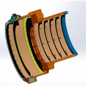
As shown on Fig. 2-2 the external baffle consists in 2 tubes of different diameter. The primary external baffle, with a diameter of 550 mm includes 3 vanes (black on the figure). The secondary external baffle includes 5 vanes. The construction of the baffle with stand-alone vanes and the external diameter of 380 mm of these vanes allowed envisaging the use of Acktar coating.
2.2 Coating trade-off
During the preliminary phases, comparison of classical paint as Aeroglaze Z306 with Acktar’s high efficiency coating indicated an advantage of the Acktar’s coating. Rapidly however, it has been noted that Acktar has limitation in terms of size of the parts that can be coated. Indeed this process is mainly developed for small optical components and specific locations while the CHEOPS baffle was intending a quite large application.
Due to the fact that one of the small mission’s objectives is to re-use as far as possible approved technologies, the Aeroglaze Z306, used on the COROT mission, was initially selected.
However, for the sake of the project and because several issues led to a reduction of the initial margins of the original design, the Acktar proposed solutions were kept and further investigated.
Down selection of the parts that can be coated with Acktar has been done. In the external baffle under responsibility of CSL only the vanes of the secondary baffle were compatible with Acktar capabilities.
One important contributor to overall straylight is the effect of the edges. Indeed all vanes edges are visible by the optics and can be directly lit by external light sources. The geometry of the edge is difficult to realise (the objective being to be as small as possible) and the simulation of the actual geometry is also complex. To validate our simulations, edge samples have been manufactured identically to the flight edges and have been coated by Acktar using Fractal Black™ and Magic Black™.
These edges effect on straylight have been measured on CSL’s BRDF bench.
2.3 Simulations
The simulation of the edges has been compared with the measurements.
θi = 0 deg θr = 170 deg
θr = 160 deg θr = 150 deg θr = 135 deg θr = 120 deg
Edge angle = 0 deg Edge angle = 30 deg
Edge angle = 45 deg Edge angle = 60 deg
Fig. 2-3: Angles definition for edge measurement
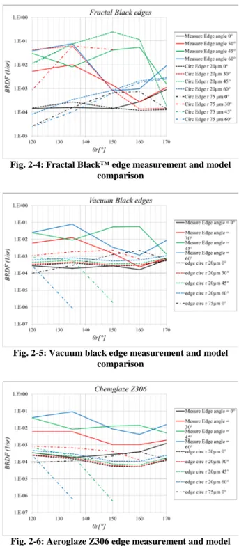
The test set-up has been modelled and various geometries of the edge have been tested: edge with radius 20 µm, with radius 75 µm and flat edge.
Fig. 2-4: Fractal Black™ edge measurement and model comparison
Fig. 2-5: Vacuum black edge measurement and model comparison
Fig. 2-6: Aeroglaze Z306 edge measurement and model comparison
All models and measurement comparison led to the same conclusion that for normal incidence (edge angle = 0°), the model fits with the results while for larger angles, the model overestimate the measurement. Nevertheless, the approach is then conservative.
After this first validation, the complete model of our external baffle with a representative model of the inner
Fig. 2-7: Results of the simulation comparing Aeroglaze Z306 and Fractal Black™.
It can be seen that solution with Acktar Fractal Black™ coating on inner vanes remains slightly better than full Aeroglaze Z306 solution.
Based on this model and in concertation with the project team, an Acktar Fractal Black™ solution for the inner vanes has been selected.
2.4 Validation
Fractal Black™ coating has already been intensively qualified ([2],[3]) but some additional validations have been performed.
First a discussion about the mounting procedure with the manufacturer of the baffle was necessary. Indeed the original integration procedure of the baffle was based on the COROT procedure which was painted with Aeroglaze Z306. It was necessary to evaluate if any procedure step has to be revalidated. Based on the selection of Fractal Black™ which is more mechanically resistant than Vacuum Black™, it was agreed that identical procedure could be used.
Secondly, due to the large size of the vanes with respect to the Acktar coating facilities, it was decided to reduce the risk to keep both solutions available (paint and Fractal Black™) up to the last minute. Final decision on the selection was made after inspection of the obtained result.
In parallel of this, thermal cycling tests on edge samples were performed in order to evaluate the adhesion of the coating on thin edges.
This test consisted in dipping the samples of Fractal Black™ and Vacuum Black™ coated edges in liquid nitrogen then heating it directly up to reaching about 15°C. This cycle has been repeated 10 times on each samples and visual inspection and tape lift tests have been performed before and after.
The result of the test is fully re-insuring since no degradation of the adhesion or of the edge visual aspect was observed despite the very constraining test.
2.5 Application
As explained earlier, the coating has been applied by Acktar on vanes in parallel to the manufacturing of Aeroglaze Z306 vanes. The final selection was made and Acktar vanes were installed.
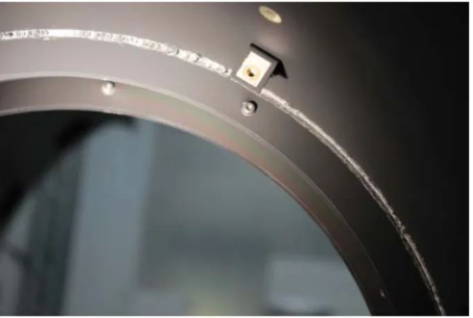
During application a question was raised about the visual aspect. Indeed, during inspection with very
powerful white light, it has been observed some colour effects on the vanes.
Fig. 2-8: Colour effect in Fractal Black™
This colour effect has been evaluated by Acktar and CSL and it was determined that this was due to a slight thickness variation due to the large size of the vane. Nevertheless, CSL’s measurements of the phenomenon indicated that this effect is very small and does not impact the overall reflectivity of the coating. Only a slight spectral change is visible on the measurements which is emphasised under very intense illumination.
Fig. 2-9: Relative comparison between black and coloured zones
2.6 Lessons learnt
The CHEOPS project allowed us getting a first experience with the use of Acktar on flight hardware. The size limitation is something that should, either be relaxed by Acktar if feasible, either be taken into account early in the project. On CHEOPS, the initial computations we performed were taking into account a full application on all surfaces which is not realistic. Secondly, Acktar coating remains fragile, even if the Fractal Black™ is more resistant than the other solutions envisaged from Acktar. During integration, slight damages were made on the coating and local corrections with black paint were performed. Unfortunately, black paint is not as black as Acktar and the correction is very visible and gives a negative visual impression on the overall part.
2.7 Status of the project
final tests campaign. The Fractal Black™ coating survived all environmental tests, including thermal cycling tests at baffle and instrument level.
3 SENTINEL-4 UVN PROJECT
3.1 Context
Sentinel-4 is an ESA space mission, part of the Copernicus program. Its instrument UVN is a high resolution spectrometer which operates in the Ultra-violet, Visible and Near-Infrared spectral ranges. Sentinel-4/UVN will be used for the continuous monitoring of the composition of the atmosphere, with both high spatial and temporal resolution. In particular, UVN will focus on tropospheric gases.
To achieve the mission goal, it is required to perform regular in-orbit calibrations of the instrument. A re-calibration is indeed necessary to ensure the radiometric accuracy, as operation conditions will for example induce drifts of the sensor gain factor. CSL was responsible of the design and test of the in-flight calibration assembly (CAA) for UVN.
Two methods are used for the in-flight calibration. One consists in illuminating the instrument with a white light source, whose drift with time and exposure to space conditions is characterized and limited. At the moment of the calibration, a flat mirror is rotated to block the view of the earth and expose instead the instrument to the calibration source. The second calibration method consists in the measurements of the sun’s irradiance as transmitted by a diffuser. Moreover, several diffusers are placed on a diffuser and the calibration is performed with several of them at different time intervals, to cross-check in case the properties of the diffusers would vary during the mission.
Fig. 3-1: UVN Sun baffle and calibration mechanism
A baffle is used to block the earth shine on the calibration diffuser, hence ensuring that only the sun is illuminating the instrument. Fig. 3-2 shows the sketch of the baffle. As it shows, the baffle has an asymmetric shape, allowing the direct view of the sun over a field of view of ±2.1° × ±0.1059°. That angular extend accounts
for the fact that the sun will be at different locations depending on the moment of the calibration. In addition of blocking completely light from the earth, the baffle requirement was that the stray-light generated by the sun would be below 0.2% inside the UVN field of view. The performance was tested by simulations as well as experimentally considering the sun at different configurations, as illustrated on Fig. 3-3.
Fig. 3-2: Sketch of the UVN calibration assembly baffle
Fig. 3-3: Sun configurations tested for stray-light performance
3.2 Coating trade-off: simulations results
The baffle was designed with the vanes placed in such a way that it minimizes the area inside the baffle which is both seen from the entrance port (critical surfaces) and the exit port (illuminated surfaces) [5]. Indeed, if a surface is seen from both the entrance and the exit the stray-light will reach the exit with first level scattering events [5].
Fig. 3-4-left shows in dark the area of the baffles which are seen from the diffuser, obtained by ray-tracing with the software FRED. As it shows, the main parts which are seen from the diffuser are mainly located close to the diffuser, as well as on and close to the inferior side of the vanes. Fig. 3-4-right shows in dark the area of the baffles which are illuminated by the sun for one given configuration. On the top of the baffle, only the superior side of the vanes (sun side) are illuminated and as they are not seen by the diffuser, they will not generate
stray-light at first level scattering. On the other side, the bottom of the baffle is illuminated and at the same time seen by the diffuser and thus this area will be responsible for first level stray-light.
A question to answer was if it would be enough to coat the baffle with black anodization of if a better coating such as Acktar’s proposed ones was required. The ray-tracing software FRED was used to compute the stray-light level when considering either black anodization of Fractal Black™. Moreover, because the qualitative analysis of critical and illuminated objects, we also simulated a hybrid case where black anodization is applied on the baffle everywhere except on the bottom of the baffle where Fractal Black™ is applied, as this area is supposed to create the more stray-light.
Fig. 3-4: (left) areas of the baffle seen from the exit port. (right) areas of the baffle seen from the entrance port
when illuminated by the sun in one example of configuration
Fig. 3-5 shows the stray-light at diffuser level as a function of the sun illumination condition, considering first level scattering events but neglecting the effect of the vane edges. The different curves correspond to the different cases of coatings considered. As it shows, the stray-light is significantly larger when black anodization is considered, and nearly equal when considering Fractal Black™ everywhere or the hybrid case.
0 2 4 6 8 10 12 14 0 0.1 0.2 0.3 0.4 0.5
1st level stray-light (no edges @vanes)
Illumination configuration # S tr ay -light ( %) Anodization Hybrid Acktar
Fig. 3-5: Stray-light (1st level scattering, not considering vanes edges) as a function of the sun illumination condition, considering different types of coatings
The stray-light coming from the edges of the vanes was
investigated separately. Fig. 3-6 shows the stray-light coming from the different vanes, considering either a black anodization coating or Fractal Black™. While the Fractal Black™ coating provides a smaller stray-light, the level with black anodization is very little. Finally, the stray-light from retro-diffusion was computed with the different coatings and the same conclusion was made. Overall, considering all contributors, it was concluded that the hybrid coating configuration is the most optimal to fulfil performance requirements while minimizing cost, also taking into account the constraints linked to applicability of the coating process due to size limitations. This configuration was thus selected [4].
1 2 3 4 5 6 7 8 9 0 0.002 0.004 0.006 0.008 0.01 0.012 Edge number S tr ay -light ( %)
1st level stray-light (edges only)
- Anodization - - Acktar vSun1 vSun2 vSun3 vSun4
Fig. 3-6: Stray-light from the vanes edges, considering different types of coatings
3.3 Experimental results
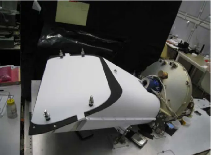
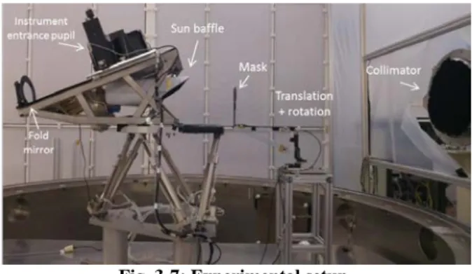
The experimental validation of the baffle performance was performed in CSL’s clear room. Fig. 3-7 shows the experimental setup. The principle is to illuminate the baffle entrance with a collimated beam to reproduce the sun illumination. The baffle is fixed on a hexapod which is used to vary its orientation and thus illuminate the baffle at different angles inside its FOV. A mask is used to block the direct illumination of the diffuser and ensure that it is only illuminated by stray-light.
Fig. 3-7: Experimental setup
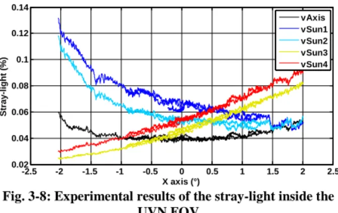
The stray-light was measured at the instrument entrance pupil level and plotted as a function of the angle on Fig. 3-8 for different sun configurations. These results confirmed that the stray-light level is below the performance requirement. Moreover, these results were remarkably close to the simulation results obtained with FRED.
-2.5 -2 -1.5 -1 -0.5 0 0.5 1 1.5 2 2.5 0.02 0.04 0.06 0.08 0.1 0.12 0.14 X axis (°) Stra y-light (%) vAxis vSun1 vSun2 vSun3 vSun4
Fig. 3-8: Experimental results of the stray-light inside the UVN FOV
3.4 Current status
The Sentinel-4/UVN calibration assembly has been fully qualified and 2 flight models have been also submitted to acceptance testing. Final delivery is expected end 2018
4 CONCLUSION
In these 2 cases, CSL implemented on flight hardware the Fractal Black™ coating proposed by Acktar. In both cases, limitations have been the size that can be coated with the current process. Nevertheless in both case the gain on straylight rejection was proven either by analysis or by test. Both instruments went through full qualification process without problem. In the case of CHEOPS, a harsh thermal cycling on edge samples also indicates the excellent resistance of the coating.
5 ACKNOWLEDGMENT
The Belgian contribution to the CHEOPS program is funded by the Federal Science Policy Office (BELSPO), in the frame of the ESA/Prodex program.
UVN calibration assembly design and development has been performed in the frame of a contract between CSL and OHB-M.
6 REFERENCES
[1]. S. Schröder, A. v. Finck, D. Katsir, U. Zeitner, A. Duparré, “Light scattering characterization of optical components – BRDF, BTDF and scatter losses”, Proc. SPIE Vol. 9272, 927202-2 (2014)
[2]. Y. Miron Salomon, N. Ariel Sternberg, I. Gouzman, G. Lempert, E. Grossman, D. Katsir, R. Cotostiano, T. Minton, « Qualification of Acktar black coating for space application », 11th ISMSE (2009)
[3]. T. Kralik, D. Katsir, “Black surfaces for infrared, aerospace, and cryogenic applications”, Proc. SPIE Vol. 7298 10.1117/12.819277 (2009)
[4]. L. Clermont, P. Blain, E. Mazy, J.Y. Plesseria, B. Marquet, Y.Stockman, "Design and tests of the sun baffle for the Sentinel-4 UVN embedded calibration assembly", Proc. SPIE Vol. 10562, 1056201 (2017) [5]. E.C. Fest, 2013, “Stray-light analysis and control”. SPIE Press