HAL Id: hal-01183142
https://hal.archives-ouvertes.fr/hal-01183142
Submitted on 6 Aug 2015
HAL is a multi-disciplinary open access
archive for the deposit and dissemination of sci-entific research documents, whether they are pub-lished or not. The documents may come from teaching and research institutions in France or
L’archive ouverte pluridisciplinaire HAL, est destinée au dépôt et à la diffusion de documents scientifiques de niveau recherche, publiés ou non, émanant des établissements d’enseignement et de recherche français ou étrangers, des laboratoires
Experimental study of impact energy absorption by
reinforced braided composite structures: Dynamic
crushing tests
Olivier Dorival, Pablo Navarro, Steven Marguet, C Petiot, M Bermudez, D
Mesnagé, Jean-François Ferrero
To cite this version:
Olivier Dorival, Pablo Navarro, Steven Marguet, C Petiot, M Bermudez, et al.. Experimental study of impact energy absorption by reinforced braided composite structures: Dynamic crushing tests. Composites Part B: Engineering, Elsevier, 2015, 78, pp.244-255. �10.1016/j.compositesb.2015.03.083�. �hal-01183142�
Experimental study of impact energy absorption by reinforced
braided composite structures: dynamic crushing tests
O. Dorivala, P. Navarroa, S. Margueta, C. Petiotb, M. Bermudezb, D. Mesnag´eb, J.-F.
Ferreroa a
Universit´e de Toulouse; Institut Cl´ement Ader (ICA); INSA, UPS, Mines Albi, ISAE, 135 av. de Rangueil, 31077 Toulouse Cedex, France
b
Airbus Group Innovations, 12 rue Pasteur, 92152 Suresnes Cedex, France
Abstract
High speed dynamic loadings such as small engine fragments, bird strike, tyre impact or ice debris are a concern for many aeronautical structures, as they can create severe damages raising safety issues. A strategy to develop dedicated mechanisms for energy absorption of high speed dynamic impact debris at sub-component level is therefore proposed by means of several reinforced foam-woven composite structures. Among the tests for evaluating the mechanical performances, dynamic crushing tests were performed on a slice of such rein-forced composite structures to evaluate their energy absorption. Using simultaneously load signal and fast camera imaging, the tests were analyzed to provide important informations such as damage mechanisms and displacement-load-energy absorption values. At the end, quantitative criterions are presented in order to distinguish the designs that have a good potential for absorbing shock energy and for getting a better understanding for designing reinforced composite structures.
Key words: Discontinous reinforcement, Fabrics/textile, Impact behaviour, Damage mechanics
1. Introduction
Over the past decades, aircrafts performances have been hugely improved thanks to the replacement of metal parts by composite structures. In the same time it has considerably transformed the job of designers and manufacturers. Starting from non primary parts in the structures, composites have progressively been involved in more and more important zones, including some zones crucial for the safety, such as rotor blades, wing parts or vertical tail plane. Development of new processes and new designs of composites structures opens a wide
URL: [email protected] (O. Dorival), [email protected] (P. Navarro), [email protected] (S. Marguet), [email protected] (C. Petiot), [email protected](M. Bermudez), [email protected] (D. Mesnag´e),
range of possibilities for decreasing fuel consumption thus increasing aircraft performances but in the same time it raises many questions regarding the safety criteria required by certification.
The focus here is put on the energy absorption capabilities of composite structures during impact [1]. Over the past decades, composite capabilities in energy absorption have been the focus of a lot of work [2, 3]. Inertial characteristics and mechanical performances of composite materials, coupled to new reinforcement techniques such as stitching or pinning raises an infinite space for designing lightweight shock absorbers in a new way and with unreachable capabilities for composite absorbers. Modeling such complex structures as shock absorbers is still a challenging task [4, 5], especially when discrete reinforcement techniques are involved. Consequently experimental evaluations remain hugely necessary for one to better know the dissipation mechanisms activated as well as to quantify the performances of such new proposed designs.
Composite have already been used as proper energy absorbers; Alghami [6] classified them according to their shapes. Inspired by energy absorption capabilities of metal tubes [7], a huge work has been conducted about energy absorption capabilities of composite tubular structures submitted to axial compression [8, 9, 10, 11, 12, 13, 14] and showed the importance of a stable crushing behaviour. Lots of studies deal with quasi-static loading of tubular structures. In [15], various types of reinforced foam core sandwich - namely simple and double corrugated, dimpled, web perpendicular and diagonal to the facings, use of tubes parallel to the facings - are used as reinforced walls of hollow rectangular tubes that are tested in edgewise compression. The authors employ the term “tied-core” to designate the use of additional core reinforcement. For metal tubular structures, foam filling is known to enhance the energy absorption performances. In [16] quasi-static axial compression of foam-filled conical metal structures are studied. In [17] foam-filled aluminium alloy tubes are tested in static and dynamic bending. This question was also addressed for composite tubular structures and again an improvement of energy absorption was found. In [18], the influence of inner and outer wall thickness and that of inner foam filling are investigated on sandwich composite bitubular structures. In [19], square hollow composite structures filled with foam are studied and several modes of failure were observed. In [20] foam-filled natural fibers composite tubes are shown to have a better crashworthiness than empty tubes. Quasi-static crushing of composite plies has also been addressed in [21]. However, the dynamic effects are likely to change the response of tubular structures. Consequently the dynamic response of composite tubes has also received a reasonable interest. Square hollow tubes are compared in static and dynamic crushing in [11, 22]. In [23], empty 2.5D-braided composite tubes were tested in low velocity axial crushing and different crushing modes were observed depending on the composite materials. In [24], composite tubes were subjected to dynamic loadings up to explosive impulse.
Another possible mode for absorbing energy is the flattening process (i.e. side compres-sion) of “ring-like” systems [25, 26]. In this area, more and more papers also address the influence of foam filling on the flattening process. [27] studied the quasi-static flattening of foam-filled composite tubes and investigated the influence of several parameters such as the dimensions, number of layers, foam filling and foam density. In [28] the authors studied the
quasi-static side compression of hexagonal and octagonal CFRP ring systems either empty or filled.
A lot of studies concern quasi-static global compression of sandwich panels with various types of cores. In [29], quasi-static global compression tests are carried out on egg-box composite sandwiches including weave fabrics. In [30], three-point-bending tests and global compression tests are performed on corrugated core sandwich structures. In [31] double layer sandwich panels involving truss core are tested. In [32] an aluminum alloy pyramidal lattice core filled with polyurethane foam is tested. Again some studies show that dynamic effects may have important influence on the results [33, 34]. Consequently, some papers also deal with low velocity penetration tests of sandwich panels. The apparatus is generally a drop tower and the indentor used is generally an hemispherical steel head whose velocity generally stays bellow 10 m/s. In [31], the impact energy is in the range [5J − 25J]. In [32] the range [20J − 60J] was investigated. In [35] the authors tested foam core sandwich reinforced by stitches in the range [1J − 70J]. In [36], foam reinforced by composite tubes is tested at several strain rates. In [37] a foldcore sandwich made from a woven fabric prepreg is tested in [5J − 60J]. The authors also tested the specimen at high velocities up to 132 m/s using a gas gun.
Behaviour of foam stabilised composites structures under dynamic impact have also raised a significant interest due to their use in aeronautics. In [38] foam-skin debonding was found to start the initiation of damage under drop weight tests. In [39], composite structures similar to helicopter blade sections were impacted by a steel ball shot at a velocity up to 140 m/s using a gas gun. The author identified the following damage scenario: damage of the front edge, skin-foam delamination, damage of the roving, penetration. Influence of discrete reinforcements of the foam core have raised the interest of several researchers. In [40], foam reinforced with various density of carbon or glass rods is tested in global compression.
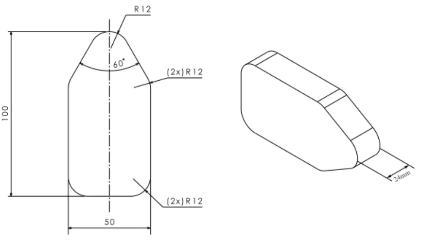
In our paper, we report results of dynamic crushing tests performed on several designs of composite structures that may be involved in several parts of aircrafts such as rotor blades, wing parts, fuselages, . . . Under compressive loading, the structures will develop mechanisms of high interest for absorbing the kinetic energy or restitute the energy stored during impact loadings. All the specimens were designed with the idea to keep exactly the same external shape as illustrated in Figure 1, the same medium density foam and comparable external fabrics. However the designs involve various reinforcement techniques such as adding inner composite walls and adding discrete elements such as stitched and sewn elements. All the designs were manufactured by Airbus following Airbus standards or Airbus specification.
Using a drop-weight tower with a flat cylindrical indentor of mass 4 kg at a speed of about 6.5 m/s, the various specimens were evaluated under crushing in normal direction to their leading edge (at 0◦ from the symmetry plane). Fast camera imaging is used to explain
precisely the chronology of the damage mechanisms involved for each design crushing, in relation with the corresponding load/displacement plot. Finally quantitative normalized results are presented that aim at providing a clear view of the capabilities of the proposed designs concerning their energy absorption. To this end, several criteria are used, such as specific energy absorption, crushing load efficiency, reserve of crushing. The discussion that follows help to select the promising designs and allows drawing some guidelines for designing
shock absorbers.
24mm
Figure 1: (left): dimensions of the external shape for all specimens, and (right): sample used for crushing tests.
2. Experimental set-up
Dynamic crushing tests were performed using a drop weight tower with a flat indentor of mass 4 kg at a velocity of 6.5 m/s. Eventually a very slight deviation (less than 2%) in the impact velocity was observed due to the apparatus. For each design, three tests were performed. Based on the good correlation between these tests, the variation in the impact velocity was considered small enough to not affect the results of the tests. During the tests the following devices were used:
• a load sensor was used for recording the crushing load between the indentor and the specimen. The sensor used was a SCAIME model K100 (50 kN) and the sampling frequency used was 20,000 Hz (sampling time of 2E-6 s);
• a fast camera was used for recording pictures in order to report the chronology of the damage mechanisms appearing in the samples during the crushing. The camera used was a FASTCAM-APX RS model 250K with recording rate set at a frequency of 20,000 Hz, obturation frequency set at 50,000 Hz, and resolution at 512x256 pixels. The scene was lighted by two spots.
The post-treatment of the tests involves several stages. First of all, fast camera pictures are analyzed manually to get a precise description of the scenario of damage that the samples undergo during the test. A DIC software already used in [41] tracks the location of the indentor on each picture. As an output, we get the displacement of the indentor versus time, which can be coupled with the load signal to draw the load/displacement plot of each test. From the displacements, velocities are computed and absorbed energy is obtained as the area under the load/displacement curve.
3. Results of crushing tests
In this section, we describe the scenario of damage that each design undergoes, based on the fast camera pictures. This allows to understand the strengths or the weaknesses of each of the specimens. The description of the damage mechanisms is correlated to the load/displacement plots to understand the shape of each plot. The load/displacement plots are normalized with respect to the reference design.
3.1. Crushing of the reference design
Figure 2: Reference design D1
Design D1 is the reference one, see Fig. 2. It is composed of a foam block wrapped in a woven composite. The foam used is polymethacrylimide foam (density 75 kg/m3, elastic
modulus 105 MPa, shear modulus 42 MPa, compressive strength 1.7 MPa, tensile strength 2.2 MPa, shear strength 1.4 MPa). The composite consists of three layers of a 2D-braiding composed of aramid 12K fibers (area weight 176 g/m2, tensile strength 2.92 GPa, tensile
modulus 109 GPa) injected with HexFlow RTM6 resin (density 1110 kg/m3, tensile modulus
2.89 GPa, tensile strength 75 MPa, flexural modulus 3.3 GPa, flexural strength 132 MPa) and oriented at ±45◦. Note that the same materials are used for all the designs presented.
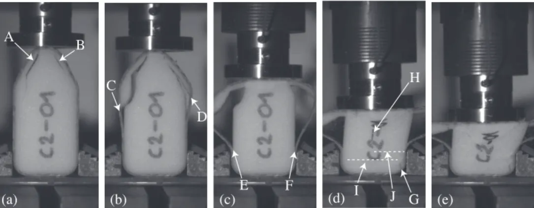
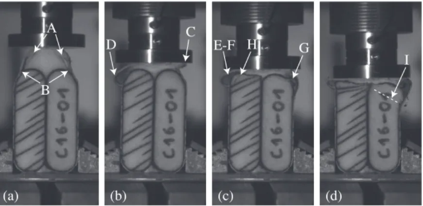
(a) A B (b) C D (c) E F (d) G H I J (e)
Some pictures from the camera are given in Fig. 3 and the corresponding load-displacement plot and energy-displacement plot are given in Fig. 4. Analysis of the fast camera pictures reveals the following damage scenario. For a better understanding the main events that are marked by capital letters in the text description are also located in Fig. 3 and in the curves shown in Fig. 4.
(a) Soon after the contact, a crack appears in the left front part of the foam (A), under the woven composite. This crack is inclined at about 17◦ from the symmetry plane in
the front end and then follows a 32◦ direction at approximately 5 mm under the fabric.
Soon, a similar crack appears in the right part (B), mainly oriented at -32◦ from the
symmetry plane, at approximately 3.5 mm from the fabric.
(b) Cracks propagate towards the rear face of the specimen and reach the interface with the fabrics at (C) and (D). The propagation of the cracks continues in the form of debondings between the foam and the fabrics. In the same time, crushing of the front foam can be noticed. Direct observations of the post mortem samples showed that what is here referred to as debonding designates in fact the breakage of the first cell of the foam under the resin.
(c) Debondings propagate simultaneously towards the rear face while fabrics are bending and the front foam is crushed by the indentor. The left debonding is stopped by the flange at (E) and the right debonding is stopped at (F).
(d) Foam crushing goes on. Fabric bending results in a complete folding of the composite on both sides. A small localized crack appears in the right rear corner of the foam (G). At (H) the crushed foam shows a triangular form that creates a longitudinal crack. At (I) a transverse crack appears at about 10 mm from the rear face due to the compression of the foam, followed by similar transverse one (J) at about 20 mm from the rear. (e) The indentor starts its rebound (K). The foam is almost totally crushed (the indentation
is 59.6 mm): the crushing reserve - defined by the ratio between the damage height of the specimen to its total height - is very small, but the energy dissipation is quite important (94%).
As the fabric quickly bends, the connexion to the foam is deteriorated. The main role of the composite skin is in participating to the initial stiffness together with the foam and to keep the specimen integrity. Consequently the reference specimen involves one main dissipation mechanism based on the crushing of the foam. The outer fabric plays no specific role in the energy absorbtion.
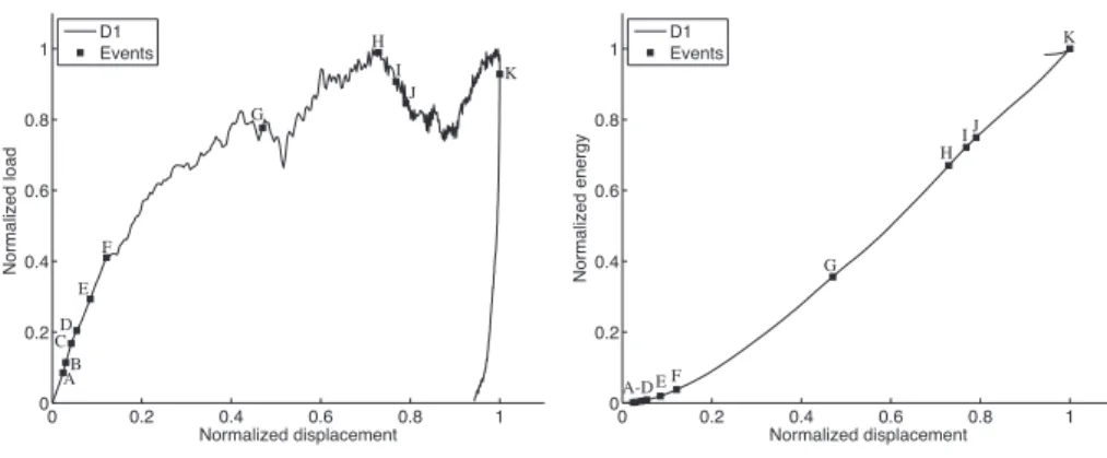
0 0.2 0.4 0.6 0.8 1 0 0.2 0.4 0.6 0.8 1 Normalized displacement N o rma lize d l o a d D1 Events AB C D E F G H I J K 0 0.2 0.4 0.6 0.8 1 0 0.2 0.4 0.6 0.8 1 Normalized displacement N o rma lize d e n e rg y D1 Events A-D EF G H IJ K
Figure 4: (left): Load-displacement plot, and (right): energy-displacement plot for D1 design
3.2. Effect of using a second fabric
Figure 5: Design D2
Starting from the same external shape, design D2 consists in using a second fabric inside the foam as illustrated in Fig. 5. To this aim, an inner foam block with similar shape and smaller dimensions is used. It is covered with three layers of semi-impregnated 3D-Interlock braiding in aramid 12K fibers (±45◦, 1 mm thick). This assembly is surrounded with foam
which is composed of two bonded parts. The whole group is covered with the three layers of 3D-Interlock braiding of aramid 12K fibers and is then injected.
(a) A (b) B C (c) D E (d) F (e) G H
Figure 6: Fast camera analysis of D2 crushing test.
Pictures of the crushing tests shown in Fig. 6 and the corresponding curves given in Fig. 7 illustrate the following scenario:
(a) After the contact with the indentor, two cracks quickly appear in the outer foam (A). (b) Cracks propagate as to create a debond at the outer foam/fabric interface (B). As the
indentor advances, these cracks open up and the front outer foam is almost completely crushed (C). Up to this stage, the inner foam is mostly spared and the inner wall has almost not moved.
(c) At (D) a crack appears in the inner foam close to the right edge and will soon result into debonding. Almost at the same time debonding takes place between the inner foam and the inner fabric in the opposite edge. As outer debondings are stopped by the flanges (E) inner debondings propagate and all the fabrics bend to help the indentor advance. (d) Internal and external fabric are bending resulting in the crushing of the internal foam and eventually closing the outer debondings. Inner debondings are stopped at about 25 mm of the rear face (F).
(e) At (G) a transverse crack is noticed at about 10 mm of the rear face, due to the collapse of the foam by compression. The foam crushed by the indentor takes a triangular shape. Both internal and external fabrics are totally folded. At (H) one can notice another transverse crack at about 40 mm of the rear. The indentor starts its rebound at (I). The sample is highly crushed (indentation is 50.1 mm) although energy absorption is quite low (84%).
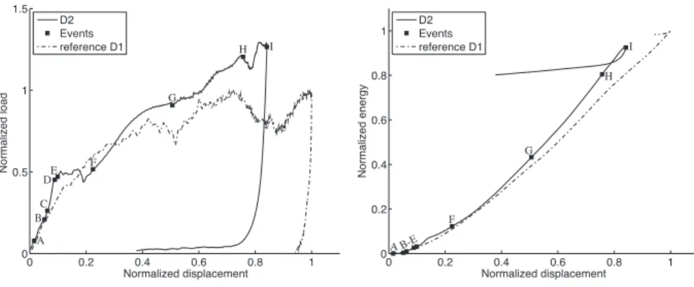
From this analysis and from the curves of Fig. 7, we can conclude that the inner fabric in design D2 does not bring any significant improvement to design D1. Cracks quickly allow the fabrics to bend outside, with only a slight increase of 29% in the crushing load. The second fabric mainly affects the initial stiffness by delaying the “softening” of the slope; this results in a slightly lower indentation length (15 mm less). The only dissipation mechanism is the continuous crushing of the inner foam that is applied on a projected area that is
smaller than for reference design D1. This explains that the absorption ratio is lower than for D1 although the peak load is 29% higher.
0 0.2 0.4 0.6 0.8 1 0 0.5 1 1.5 Normalized displacement N o rma lize d l o a d D2 Events reference D1 A B C DE F G H I 0 0.2 0.4 0.6 0.8 1 0 0.2 0.4 0.6 0.8 1 Normalized displacement N o rma lize d e n e rg y D2 Events reference D1 I H G F B-E A
Figure 7: (left): Load-displacement plot, and (right): energy-displacement plot for D2 design.
3.3. Effect of using a transverse wall
The idea of inserting a transverse wall is realized through the use of two blocks of foam covered with one layer of braiding. To achieve the same number of layers, the assembly is wrapped with two layers braiding before injection. The side voids are filled with an aramid dry tow injected with the same resin. The final design is illustrated in Fig. 8.
(a) A B C (b) D (c) E F H G (d) I
Figure 9: Fast camera analysis of D3 crushing test.
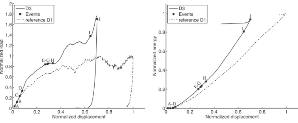
Pictures shown in Fig. 9 and curves from Fig. 10 illustrates the following events:
(a) A crack appears in the front bumper close to the right fabric (A). Soon the crack reaches the foam/fabric interface (B) and opens as the lower skin starts to bend outside to help the indentor with the crushing of the foam. At (C) a second crack appears in the left part of the front bumper that has already reached the interface with the fabric.
(b) The resulting debonding propagates in the front bumper while both fabrics bend outside and the front foam is crushed. Debonding is stopped at (D).
(c) The rear edges start to collapse (E). The right skin of the front bumper breaks by folding (F) as foam crushing goes on in the front bumper. A small crack appears in one of the rear edge (G) of the sample when it is crushed against the flange. The left fabric also breaks in bending (H).
(d) At (I), a debonding appears in the other rear edge. Both rear edges are crushed in a square shape against flanges. The indentor starts its rebound (J). Damage of the foam in the rear bumper is almost non-existent (indentation is only 41.8 mm) associated with an important energy absorption (94 %).
The pictures in Fig. 9 and the curves in Fig. 10 show that the presence of the inner wall has two positive effects: firstly it avoids the global bending of the fabric, what delays the softening of the initial stiffness resulting in a higher crushing load; secondly it avoids the rear foam being crushed prematurely. This leaves an important part of the design mostly undamaged.
0 0.2 0.4 0.6 0.8 1 0 0.2 0.4 0.6 0.8 1 1.2 1.4 1.6 1.8 2 Normalized displacement N o rma lize d l o a d D3 Events reference D1 A B C D E-G H I J 0 0.2 0.4 0.6 0.8 1 0 0.2 0.4 0.6 0.8 1 Normalized displacement N o rma lize d e n e rg y D3 Events reference D1 A-D E-G H I J
Figure 10: (left): Load-displacement plot, and (right): energy-displacement plot for D3 design.
3.4. Effect of reinforcing the front bumper in design D3
Figure 11: Design D3R
Design D3R is similar to the D3 design in which the front bumper is reinforced by manual continuous sewing, as illustrated in Fig. 11. The front foam block was pre-drilled (diameter 1.5 mm) along several holes. The sewing used doubled tow of carbon 6K for each hole with an increment of 7.5◦ between the direction of each hole. The pitch between two
(a) A B (b) C D F E G (c) H I J K-L (d) M (e)
Figure 12: Fast camera analysis of D3R crushing test.
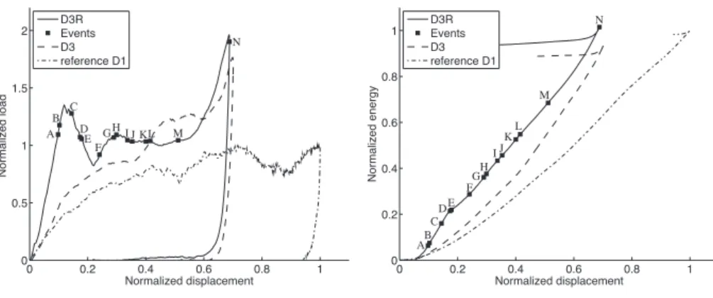
As illustrated in Fig. 12 and in the corresponding load-displacement plot and the energy-displacement plot given in Fig. 13, the following mechanisms occur:
(a) Just after the contact, the very rear part of the foam is settled because the reinforcements in the front bumper bring additional stiffness. Then one inclined crack appears in the front bumper (A), initiated from the foam leading edge. Soon it follows the direction of the side reinforcement. Immediately a symmetric crack appears (B) in the front bumper. Both cracks are slightly open but no debonding with the fabric is noticed: reinforcements link the foam and the fabric together.
(b) Settling of the rear foam goes on, specially in the corners (debonding at (C)), while the front bumper looks stiff. The inner wall bends due to the forces exerted by the reinforcements. The central reinforcement seems to break at (D) (the breakage is not clearly visible on the picture, but a sudden release of the inner wall is noticed). A very small foam/fabric debonding is noticed in the front bumper at (E), but stays very localized due to the reinforcements keeping everything together. Crushing is then favored since the sample keeps its structure. The left skin folds against the indentor at (F). In the front bumper, cracks have generated several “parts” of foam; two of them start to bend and breaks at (G).
(c) A small crack appears in the left rear part of the front bumper (H). Another crack appears in the front bumper, the beginning of which follows the direction of one re-inforcement. At (I), the inner fabric of the front bumper folds in its middle without debonding from the outer fabric. A small debonding between the outer braid and the inner braid is noticed at (J). One of the side reinforcements buckles (K) and quickly breaks (L).
(d) The outer fabric of the front bumper folds (M).
(e) The indentor starts its return at (N). As for D3, the rear foam is mostly spared (inden-tation is 41.0 mm) and the energy absorption is slightly less than for D3.
From the analysis of pictures in Fig. 12 and from the curves given in Fig. 13, one can draw the following conclusion: compared to D3, the two major effects of reinforcements in D3R is in the initial stiffness and in the resulting peak load. The dissipation mechanism involves foam crushing and breakage of the reinforcements, but the latter does not present a substantial improvement compared to D3.
0 0.2 0.4 0.6 0.8 1 0 0.5 1 1.5 2 Normalized displacement N o rma lize d l o a d D3R Events D3 reference D1 A B C D E F GHI J KL M N 0 0.2 0.4 0.6 0.8 1 0 0.2 0.4 0.6 0.8 1 Normalized displacement N o rma lize d e n e rg y D3R Events D3 reference D1 AB C DE F GH IJ KL M N
Figure 13: (left): Load-displacement plot, and (right): energy-displacement plot for D3R design.
3.5. Effect of using a longitudinal wall
Figure 14: Design D4
Instead of using discontinuous reinforcement to improve the initial stiffness, Design D4 is made of two oblong foam blocks covered with one layer of braiding of carbon 12K fibers, see Fig. 14. The shape is completed by a front block and the rear void is filled with an aramid dry tow. To ensure that the front edge includes three layers of composite as in other designs, a core cap fabric is used to cover the front foam. The assembly is surrounded by an external braiding and is injected with resin.
(a) A B C (b) D (c) E (d) F G H (e) I J K L M (f) N O
Figure 15: Fast camera analysis of D4 crushing test.
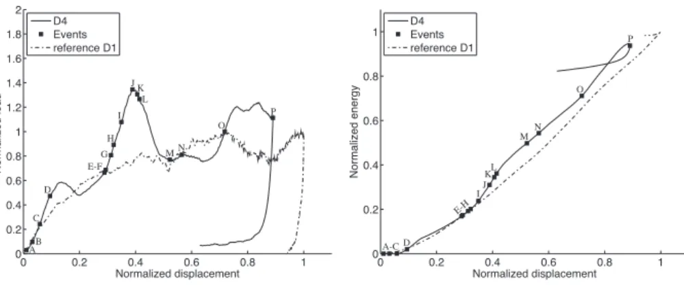
Fig. 15 and Fig. 16 illustrates the following scenario:
(a) In the front bumper, a crack appears in the right part of the foam (A) just before that a foam/fabric debonding takes place in the left part (B). As the indentor advances, the front foam crushes and the fabrics bend outside, opening both the debonding and the crack. The crack reaches the edge between the outer fabric and the right carbon bumper (C).
(b) Similarly the left debonding reaches the edge between the outer fabric and the left bumper and continues in a debonding between the outer fabric and the carbon composite of the left bumper. Debondings propagate and are soon stopped at the interface with the oblong bumpers (D). The fabrics are then put into bending.
(c) The indentor advances while the right fabric exhibits folding consecutive to bending. Whereas the rear bumper foam is mostly undamaged, the front foam is totally pulverized and starts pushing on the rear bumpers (E).
(d) An important crack appears in a rear left bumper (F). It propagates to the rear in an inclined direction and opens to help the indentor compression. A local crack takes place in the front of the right rear bumper close to the central wall (G). The left crack allows the bending of the left foam which results in a small transverse crack (H) that immediately reaches the foam/fabric interface.
(e) Another crack appears in the front of the right bumper (I) that continues in debonding. Another important crack appears in the left bumper (J) due to the difference between the part of the foam put into bending and the one put into compression. Debonding between the left foam and the central wall takes place (K), propagates and opens up. At (L) a transverse crack appears in the right foam due to bending. Simultaneously the right debonding propagates, reaches the right flange (M) and stops.
(f) At (N) two other cracks appear due to bending of the left foam. Suddenly a crack appears (O) by buckling of the mean wall. Debonding in the mean plane is immediately closed as the later crack is opened. When the indentor rebounds (P), the sample is almost totally crushed and bent against the flanges. The foam left undamaged is very small (the indentation is 53.1 mm).
In this case the design does not work properly. Although the inner fabrics avoid a global buckling of the full fabric, they do not bring any sensible additional stiffness or dissipation. Instead, the main effect of the rear bumpers is to “split” the foam into two parts, what helps them in buckling. As a consequence, the crushing of the foam is deteriorated and partly replaced by bending and crushing against the flanges.
0 0.2 0.4 0.6 0.8 1 0 0.2 0.4 0.6 0.8 1 1.2 1.4 1.6 1.8 2 Normalized displacement N o rma lize d l o a d D4 Events reference D1 AB D C E-F G H I J K L MN O P 0 0.2 0.4 0.6 0.8 1 0 0.2 0.4 0.6 0.8 1 Normalized displacement N o rma lize d e n e rg y D4 Events reference D1 A-C D E-H I J KL M N O P
Figure 16: (left): Load-displacement plots and (right): energy-displacement plot for D4 design.
3.6. Effect of reinforcing design D4
Starting from the idea of strengthening oblong bumpers from design D4, Design D4R oblong chambers and their carbon fabrics are reinforced by stitching, see Fig. 17. Stitches were made of carbon 6K fibers oriented at ±60◦ from the symmetry plane (that is +60◦
in a given plane and −60◦ in the next plane, the pitch between two planes is 6 mm). The
distance between two stitches in a given plane is 6 mm. Note that each oblong chamber and its carbon fabric coverage was separately stitched before being assembled. To ensure that the front edge includes three layers of composite as in other designs, a core cap fabric has been put on the top of the front foam. The assembly is surrounded by an external braiding and is injected with resin.
(a) B A (b) C D (c) G E-F H (d) I
Figure 18: Fast camera analysis of D4R crushing test.
Pictures from the camera shown in Fig. 18 in relation with curves in Fig. 19 illustrates the following events:
(a) Two cracks appears under the fabrics in the front bumper (A). As the indentor advances, the front foam is crushed and the cracks reach the interface but the corresponding debondings are soon stopped at the joint with rear bumpers (B).
(b) Very soon, bending of the fabrics is very important because it remains local. The right fabric breaks (C) just before the left one shows an important damage close to the joint with the rear part (D). The front foam is almost completely crushed. Deformation and damage in the two rear bumpers are very low.
(c) Deformations now appear in the rear bumpers, mainly behind the indentor. Debonding takes place in the left rear bumper (E) but is quickly stopped by the buckling of the left fabric (F). A second buckling appears in the right fabric (G). A localized crack appears in the front part of the left bumper (H) quickly followed by a transverse crack in the right one (I) that creates debonding.
(d) Debondings propagate only very moderately. The crushing of the foam is in accordance with the orientation of the stitches, and only in the vicinity of the indentor. When the indentor returns at (J), the two rear bumpers are very lowly damaged, mainly behind
the indentor. The crushing reserve is important (indentation 32.3 mm) but the energy absorption is a little bit lower than for other design (84 %).
The influence of the stitches is very important. As for D4, the presence of the rear bumpers stops the global bending of the fabric. However in addition, stitches keep the shape of the structure together and avoids the apparition of long cracks or debondings leading to catastrophic buckling for D4. The initial stiffness is approximately maintained during all the crushing. The increase in the crushing load is very significant and a large part of the design remains completely undamaged.
0 0.2 0.4 0.6 0.8 1 0 0.5 1 1.5 2 2.5 3 3.5 Normalized displacement N o rma lize d l o a d D4R Events D4 reference D1 A B CD-F G HI J 0 0.2 0.4 0.6 0.8 1 0 0.2 0.4 0.6 0.8 1 Normalized displacement N o rma lize d e n e rg y D4R Events D4 reference D1 A BC DEF G H-I J
Figure 19: (left): Load-displacement plots and (right): energy-displacement plot for D4R design.
4. Comparisons and discussion
In this section, we try to quantify the performances of the designs tested based on several criteria defined as follows:
• the peak load is the maximum load during the test:
Fpeak = max(F ) (1)
• the average load is the average load taken on the post-linear part of the plot, and excluding the rebound of the indentor:
Faver = 1 t2− t1 Z t2 t1 F(t)dt (2)
• the load efficiency is defined as the ratio between the average load and the peak load. It quantifies how efficient the crushing mode is. Indeed a load efficiency of 1 would mean a constant load during the crushing stage, consequently the absorbed energy would be maximum for a given maximum load:
κ= Faver
• the usable concept left ¯L is defined as the length of the sample that is almost undamaged after the test. By “usable concept” we mean to indicate the part of the foam which is not condensed and which exhibits no visible cracks. The idea is to evaluate the part of the concept that would be left in case that another impact takes place, or in case the first impact is more energetic;
• the crushing reserve ratio designate the ratio of the usable concept left to the total length of the design; it gives the same information as the usable concept left but in term of percentage:
CRR= L¯
Lspecimen
(4)
• the specific energy absorption is defined as the ratio of the energy absorbed during the test to the mass of the sample:
SEA= Eabs mspecimen
(5)
• the effective absorption ratio is the ratio of the absorbed energy to the initial energy:
η= Eabs E0
(6)
The first three criteria are defined based on the load signal; the usable concept left and consequently the crushing reserve are defined manually based on the fast camera analysis; the energetic criteria require the evaluation of the initial and final energy. The initial energy is derived as the initial kinetic energy of the indentor. The absorbed energy corresponds to the area under the load-displacement curve. The results are summarized in Table 1. Note that the values are normalized with respect to the reference design.
Note that in case of catastrophic crushing events for design D4, the concept is deteriorated in such a way that the sample works in a wrong manner very prematurely (after marks G-H in Fig. 16). Indeed the stiffness of the design suddenly drops down due to large cracks appearing in the foam, and consequently after the catastrophic crushing occurs, the energy is dissipated in a wrong and rather chaotic manner, what falsifies the interpretation of the area under the load-displacement plot. For that reason the values for design D4 were taken at the time when the catastrophic crushing occurred (at mark H in Fig. 16). The reason for this is to avoid erroneous interpretation of the potential of design D4 compared to other designs.
Design D1 D2 D3 D3R D4 D4R
Catastrophic crushing ? No No No No Yes No
Peak load (normalized) 1 1.29 1.76 1.96 1.35 3.10
Average load (normalized) 0.79 0.95 1.11 1.21 0.93 1.71
Load efficiency [%] 79% 73% 63% 62% 69% 55%
Usable concept left [m] 0.024 0.039 0.048 0.047 0.016 0.062
Crushing reserve ratio [%] 24% 39% 48% 47% 16% 62%
Specific energy absorption (normalized) 1 0.49 0.68 0.61 0.22 0.46
Effective absorption ratio [%] 94% 84% 94% 91% 32% 84%
Table 1: Crushing test results.
It is no surprise that the lowest peak load is for the reference design D1 that is not reinforced. Nevertheless this design exhibits the best load efficiency, which means the less peaks and drops in the load, and by far the D1 design has the best specific energy absorption due to its very low mass. However the crushing reserve is very small. This means that this design would probably not be sufficient in case of a more energetical impact.
Design D2 presents a low peak load and a low average load since the two braidings bend very quickly and do not participate to the initial stiffness of the sample. The principal mechanism that dissipates energy is the foam crushing, which needs to damage an important part of the sample (low crushing reserve). For these crushing tests, the reinforcement in D2 has no sensible effect in improving the performances of the reference design. Besides, it must be noticed that the mass of the inner braiding is important and compromises the specific energy absorption.
Design D3 shows important peak load and average load. This is due to the presence of the inner wall that blocks the bending of the outer fabric and that stops foam/fabric debonding. The inner wall also holds the rear foam from crushing what explains that the crushing reserve is good. Additionally the specific absorption ratio is also very satisfactory compared to other reinforced designs.
Reinforcement of D3 by continuous sewing leads to design D3R whose results are very close to those of D3. Peak load and average load are just slightly better and the crushing reserve is the same. Additional weight brought by reinforcements moderately decreases the specific absorption ratio. For the considered crushing tests, design D3R does not appear as a sensitive improvement of D3. However, it must be reminded that reinforcements have perfectly worked and they should be of more interest for other type of loadings.
Design D4 is the only one that exhibits a catastrophic crushing event. The large longi-tudinal crack that appears in the rear bumper put the foam into bending. Consequently the foam breaks in bending instead of being crushed continuously. Most of the energy is then dissipated against the flanges since the design does not absorb correctly. This is the reason for the very low crushing reserve and the very low absorption ratio.
However, by reinforcing design D4 with stitches, we get the design D4R which shows very promising performances. The peak load is by far the most important one, but also the average load is very high compared to the other designs. The important peak load is the
reason for the low load efficiency but in this case it can not be interpreted as a disadvantage of the design. What is even more promising is the very important crushing reserve of 62%. The explanation is that energy is continuously dissipated by foam crushing coupled with breakage of the stitches. Reinforcements have led to a very efficient design regarding the stiffness, the dissipation mechanisms involved, and the consumption of the design. This design presents good results for all the criteria, except the effective absorption ratio due to the weight of stitches.
The previous analysis shows that improvements of the simple reference design D1 require to take some specific decision in term of design. It looks necessary to retain or to delay the global bending of the outer fabric in order to improve the crushing force, but also to avoid long cracks in the foam that lead to early catastrophic deterioration of the design. This can be done either by an additional wall that holds the fabric, or by discrete reinforcements such as stitches or sewing. Such reinforcements can be of high interest in terms of energy dissipation and concept consumption, as shown by design D4R. However any type of rein-forcements obviously decreases the specific energy ratio. Fig. 20 illustrate the performances of the designs. Choosing to reinforce or not requires referring to precise specifications. Es-pecially Fig. 20-right tends to show that the choice is a question of compromise between the crushing reserve and the specific energy absorption, figured by the dotted line. However following the idea of reinforcing the reference design D1, it would be very interesting to study the influence of the size/number/material of such reinforcements in order to optimize the designs. Such optimization could drastically improve the specific energy absorption of the reinforced designs without decreasing the crushing reserve, what would result in ideal shock absorbers. 0 10 20 30 40 50 60 70 80 0 10 20 30 40 50 60 70 80 90 100
Crushing reserve ratio (%)
Ef fe ct ive a b so rp ti o n ra ti o (% ) D1 D2 D3 D3R D4 D4R 0 10 20 30 40 50 60 70 80 0 0.2 0.4 0.6 0.8 1
Crushing reserve ratio (%)
N o rma lize d sp e ci fi c e n e rg y a b so rt io n D1 D2 D3 D3R D4 D4R
Figure 20: (left): Absorption ratio versus crushing reserve plot, and (right): Specific energy absorption versus crushing reserve plot.
5. Conclusion
Crushing tests using a drop weight tower were performed on several composite structures involving various type of reinforcement mechanisms. These tests were analyzed based on the load signal and fast camera pictures taken during the crushing.
First of all this has led to a very precise understanding of the damage scenarios involved for each design. This gives important clues concerning the decisions that need to be taken in term of design: avoid global bending of the outer fabric, avoid catastrophic global event that loads the design in a wrong manner, add specific reinforcements to help the dissipation and keep a good reserve of crushing. Complementary to picture analysis, quantitative criteria have been derived that helps to summarize the differences between the designs.
By comparisons to the reference design D1, design D4R looks the most interesting. D3 and perhaps D3R also show promising performances. However all reinforced designs bring an additional weight, as well as manufacturing complexities. Weight optimization can nevertheless be considered in the selection of the constitutive materials. The decision must be taken considering all these parameters plus the global cost of each design. However, further studies would be interesting in order to optimize the proposed reinforcement designs. Finally one must note that crushing tests challenge the samples in a global way. Similar study must also be performed for different types of loadings. In a complementary paper, we will report the results of tests performed on the same designs impacted by a canon ball at 100 m/s, what challenges the samples in a local way with a different energy and different velocity. The question of modeling the behavior of such structures is also a challenging one that is in progress.
Acknowledgment
Authors wish to gratefully acknowledge support from Airbus for this project.
References
[1] Serge Abrate. Impact on Composite Structures. Cambridge University Press, 1998. Cambridge Books Online.
[2] A.G. Mamalis, M. Robinson, D.E. Manolakos, G.A. Demosthenous, M.B. Ioannidis, and J. Carruthers. Crashworthy capability of composite material structures. Composite Structures, 37(2):109 – 134, 1997. [3] S. Ramakrishna. Microstructural design of composite materials for crashworthy structural applications.
Materials & Design, 18(3):167 – 173, 1997.
[4] D. Coutellier and P. Rozycki. Multi-layered multi-material finite element for crashworthiness studies. Composites Part A: Applied Science and Manufacturing, 31(8):841 – 851, 2000.
[5] P. Navarro, J. Aubry, S. Marguet, J.-F. Ferrero, S. Lemaire, and P. Rauch. Semi-continuous approach for the modeling of thin woven composite panels applied to oblique impacts on helicopter blades. Composites Part A: Applied Science and Manufacturing, 43(6):871 – 879, 2012.
[6] A.A.A Alghamdi. Collapsible impact energy absorbers: an overview. Thin-Walled Structures, 39(2):189 – 213, 2001.
[7] F. Schneider and N. Jones. Impact of thin-walled high-strength steel structural sections. Proceedings of the Institution of Mechanical Engineers, Part D: Journal of Automobile Engineering, 218(2):131–158, 2004.
[8] Gary L. Farley and Robert M. Jones. Crushing characteristics of continuous fiber-reinforced composite tubes. Journal of Composite Materials, 26(1):37–50, 1992.
[9] Mamalis A.G., Yuan Y.B., and Viegelahn G.L. Collapse of thin-wall composite sections subjected to high speed axial loading. International journal of vehicle design, 13(5-6):564–579, 1992.
[10] S. Ramakrishna and H. Hamada. Energy absorption characteristics of crashworthy structural composite materials. Key engineering materials, 141-143:585–622, 1998.
[11] A.G. Mamalis, D.E. Manolakos, G.A. Demosthenous, and M.B. Ioannidis. Energy absorption capability of fibreglass composite square frusta subjected to static and dynamic axial collapse. Thin-Walled Structures, 25(4):269 – 295, 1996.
[12] A.G. Mamalis, D.E. Manolakos, M.B. Ioannidis, and D.P. Papapostolou. On the crushing response of composite sandwich panels subjected to edgewise compression: experimental. Composite Structures, 71(2):246 – 257, 2005.
[13] A.G. Mamalis, D.E. Manolakos, M.B. Ioannidis, and D.P. Papapostolou. On the response of thin-walled CFRP composite tubular components subjected to static and dynamic axial compressive loading: experimental. Composite Structures, 69(4):407 – 420, 2005.
[14] A.G. Mamalis, D.E. Manolakos, M.B. Ioannidis, and D.P. Papapostolou. On the experimental inves-tigation of crash energy absorption in laminate splaying collapse mode of FRP tubular components. Composite Structures, 70(4):413 – 429, 2005.
[15] G. Pitarresi, J.J. Carruthers, A.M. Robinson, G. Torre, J.M. Kenny, S. Ingleton, O. Velecela, and M.S. Found. A comparative evaluation of crashworthy composite sandwich structures. Composite Structures, 78(1):34 – 44, 2007.
[16] Z. Ahmad and D.P. Thambiratnam. Crushing response of foam-filled conical tubes under quasi-static axial loading. Materials & Design, 30(7):2393 – 2403, 2009.
[17] Isabel Duarte, Matej Vesenjak, Lovre Krstulovi´c-Opara, Ivan An˘zel, and Jos´e M.F. Ferreira. Manufac-turing and bending behaviour of in situ foam-filled aluminium alloy tubes. Materials & Design, (-):–, 2014.
[18] F. Tarlochan, S. Ramesh, and S. Harpreet. Advanced composite sandwich structure design for en-ergy absorption applications: Blast protection and crashworthiness. Composites Part B: Engineering, 43(5):2198 – 2208, 2012.
[19] F. Tarlochan and S. Ramesh. Composite sandwich structures with nested inserts for energy absorption application. Composite Structures, 94(3):904 – 916, 2012.
[20] Libo Yan, Nawawi Chouw, and Krishnan Jayaraman. Effect of triggering and polyurethane foam-filler on axial crushing of natural flax/epoxy composite tubes. Materials & Design, 56(0):528 – 541, 2014. [21] H.A. Israr, S. Rivallant, and J.J. Barrau. Experimental investigation on mean crushing stress
charac-terization of carbon-epoxy plies under compressive crushing mode. Composite Structures, 96(0):357 – 364, 2013.
[22] M.R. Bambach, M. Elchalakani, and X.L. Zhao. Composite steel-CFRP SHS tubes under axial impact. Composite Structures, 87(3):282 – 292, 2009.
[23] Cyril Priem, Ramzi Othman, Patrick Rozycki, and Damien Guillon. Experimental investigation of the crash energy absorption of 2.5D-braided thermoplastic composite tubes. Composite Structures, 116(0):814 – 826, 2014.
[24] D. Kakogiannis, S. Chung Kim Yuen, S. Palanivelu, D. Van Hemelrijck, W. Van Paepegem, J. Wastiels, J. Vantomme, and G.N. Nurick. Response of pultruded composite tubes subjected to dynamic and impulsive axial loading. Composites Part B: Engineering, 55(0):537 – 547, 2013.
[25] E. Mahdi and A.M.S. Hamouda. Energy absorption capability of composite hexagonal ring systems. Materials & Design, 34(0):201 – 210, 2012.
[26] M.M. Davoodi, S.M. Sapuan, A. Aidy, N.A. Abu Osman, A.A. Oshkour, and W.A.B. Wan Abas. Development process of new bumper beam for passenger car: A review. Materials & Design, 40(0):304 – 313, 2012.
[27] Abbas Niknejad, Hassan Assaee, Seyed Ali Elahi, and Ali Golriz. Flattening process of empty and polyurethane foam-filled E-glass/vinylester composite tubes: An experimental study. Composite
Struc-tures, 100(0):479 – 492, 2013.
[28] T.A. Sebaey, E. Mahdi, A. Shamseldin, and E.O. Eltai. Crushing behavior of hybrid hexago-nal/octagonal cellular composite system: All made of carbon fiber reinforced epoxy. Materials & Design, 60(0):556 – 562, 2014.
[29] S.H. Yoo, S.H. Chang, and M.P.F. Sutcliffe. Compressive characteristics of foam-filled composite egg-box sandwich panels as energy absorbing structures. Composites Part A: Applied Science and Manufacturing, 41(3):427 – 434, 2010.
[30] Jin Zhang, Peter Supernak, Simon Mueller-Alander, and Chun H. Wang. Improving the bending strength and energy absorption of corrugated sandwich composite structure. Materials & Design, 52(0):767 – 773, 2013.
[31] Jian Xiong, Ashkan Vaziri, Li Ma, Jim Papadopoulos, and Linzhi Wu. Compression and impact testing of two-layer composite pyramidal-core sandwich panels. Composite Structures, 94(2):793 – 801, 2012. [32] Guoqi Zhang, Bing Wang, Li Ma, Linzhi Wu, Shidong Pan, and Jinshui Yang. Energy absorption
and low velocity impact response of polyurethane foam filled pyramidal lattice core sandwich panels. Composite Structures, 108(0):304 – 310, 2014.
[33] R.L. Woodward, G.T. Egglestone, B.J. Baxter, and K. Challis. Resistance to penetration and com-pression of fibre-reinforced composite materials. Composites Engineering, 4(3):329 – 341, 1994. [34] R.A.W. Mines and Norman Jones. Approximate elastic-plastic analysis of the static and impact
be-haviour of polymer composite sandwich beams. Composites, 26(12):803 – 814, 1995.
[35] Fan Xia and Xiao-Qing Wu. Study on impact properties of through-thickness stitched foam sandwich composites. Composite Structures, 92(2):412 – 421, 2010.
[36] R.A. Alia, W.J. Cantwell, G.S. Langdon, S.C.K. Yuen, and G.N. Nurick. The energy-absorbing char-acteristics of composite tube-reinforced foam structures. Composites Part B: Engineering, 61(0):127 – 135, 2014.
[37] S. Heimbs, J. Cichosz, M. Klaus, S. Kilchert, and A.F. Johnson. Sandwich structures with textile-reinforced composite foldcores under impact loads. Composite Structures, 92(6):1485 – 1497, 2010. [38] S. Rivallant, J.-F. Ferrero, and J.-J. Barrau. Dynamic buckling of foam stabilised composite skin.
Composites Structures, 72(4):486 – 493, 2006.
[39] I. Tawk, J. Aubry, P. Navarro, J.-F. Ferrero, S. Marguet, S. Rivallant, S. Lemaire, and P. Rauch. Study of impact on helicopter blade. Engineering Failure Analysis, 24(0):38 – 45, 2012.
[40] J. Zhou, Z.W. Guan, W.J. Cantwell, and Y. Liao. The energy-absorbing behaviour of foam cores reinforced with composite rods. Composite Structures, 116(0):346 – 356, 2014.
[41] J.-C. Passieux, P. Navarro, J.-N. P´eri´e, S. Marguet, and J.-F. Ferrero. A digital image correlation method for tracking planar motions of rigid spheres: application to medium velocity impacts. Experi-mental Mechanics, 54(8):1453–1466, october 2014.