Amélioration de la résistance à la fissuration des bétons
projetés: composition des mélanges et mise en place
«
Improving the Cracking Resistance of Shotcrete: Mix
Designs and Placement»
Thèse
Bruce Gandhi Menu
Doctorat en génie civil
Philosophiæ doctor (Ph. D.)
Québec, Canada
© Bruce Gandhi Menu, 2021
ii
Résumé
Le béton projeté est une méthode de mise en place rapide, économique et polyvalente qui offre de multiples avantages par rapport au béton conventionnel dans divers types de constructions nouvelles et dans les réparations. Un des grands avantages du béton projeté est de permettre une mise en place sur des surfaces fortement irrégulières en utilisant peu on même aucun coffrage. Cependant, ces mêmes caractéristiques rendant le béton projeté avantageux et polyvalent peuvent le rendre vulnérable à la fissuration due au retrait restreint. Cette vulnérabilité vient de la restriction élevée inhérente à de nombreuses applications (projection adhérente sur substrat rigide). En effet, le béton développera des contraintes internes s’il ne peut manifester ses changements volumétriques librement, ce qui peut conduire à de la fissuration lorsque ces contraintes atteignent la résistance en traction du matériau. La fissuration des réparations due au retrait restreint est sans aucun doute un des plus grands défis auxquels l’industrie des réparations en béton fait face aujourd’hui. La fissuration peut raccourcir les années de service d’une structure en béton (corrosion accélérée, délamination, etc.) et engendre souvent des coûts des maintenances supplémentaires importants. Il existe peu d’informations fiables dans la littérature sur les paramètres qui influencent la fissuration due au retrait restreint des bétons projetés ainsi que sur leur comportement à long terme en service. Ce manque d’informations à propos de l’influence des différentes composantes du mélange et de la mise en place des bétons projetés rend difficile, voire impossible, la prédiction du comportement à long terme des bétons projetés face aux problèmes de fissuration. De plus, l’ensemble des paramètres individuels affectant la fissuration due au retrait restreint est très difficile à identifier. Pour cette raison, il est devenu impératif de caractériser le comportement volumétrique des bétons projetés au moyen d’essais de retrait restreint. Dans cette thèse, l’évolution de différentes propriétés à l’état frais et durci telles que la consistance de projection, le rebond, la résistance à la compression, la résistance à la traction par fendage, le module élastique, le retrait libre et le retrait restreint est étudiée. Ce projet se concentre particulièrement sur les mélanges et leur composition, la méthode de mise en place et le potentiel de fissuration due au retrait restreint. Le potentiel de fissuration sera évalué au moyen d’une procédure d’essai annulaire qui a récemment été adaptée et amélioré pour les bétons projetés. À partir des données expérimentales générées, une analyse approfondie du développement des contraintes et de la résistance à la fissuration des bétons projetée sera conduite.
Mots clés : béton projeté, fissuration, retrait restreint, restriction, réparations, rebond, retrait libre, essai
iii
Abstract
Shotcrete is a fast, cost-saving, sustainable and versatile concrete placement method that offers numerous advantages over conventional concrete in a variety of new construction and repair works. One of the major benefits of the shotcrete process is that it can be sprayed over irregular surfaces and can cover large surfaces with little or no formwork. Howbeit, these same versatile features also often make shotcrete vulnerable to restrained shrinkage cracking. Cracking occurs mainly because of the highly restrained conditions that are inherent in many shotcrete applications (spraying on a rigid substrate). If shrinkage is restrained, internal tensile stresses are progressively induced in the element which can lead to cracking when the stresses eventually exceed the tensile strength of the material. Cracking of repair materials is unarguably one of the major challenges facing the repair industry worldwide today. Cracking can shorten the service life of concrete structures (accelerated corrosion, delamination, etc.) and often requires significant additional costly maintenance. Yet, reliable material data on parameters that influence the long-term service life and cracking in-place shotcrete is scarce. This lack of information on the influence of mixture composition as well as the placement process makes it difficult, if not impossible, to predict the long-term cracking behaviour of shotcrete. Furthermore, key mixture parameters that lead to cracking have been very difficult to identify. For this reason, it has become imperative for material characterization to be made on the basis of a restrained shrinkage test. In this thesis, different fresh and hardened shotcrete properties such as spraying consistency, rebound, compressive strength, splitting tensile strength, elastic modulus, free shrinkage, and restrained shrinkage deformation are investigated. The project focuses particularly on mix designs and compositions, placement process and the potential for cracking due to restrained shrinkage. The shrinkage ring test method which has been recently adapted and improved for shotcrete will be used to evaluate the cracking potential. Based on the experimental data that will be generated, an in-depth analysis of stress development and cracking resistance of shotcrete will be conducted.
Keywords: shotcrete, restrained shrinkage, cracking, restrained conditions, repair materials, free
iv
Table of Contents
Résumé ... ii Abstract ... iii Table of Contents ... iv List of Tables ... ix List of Figures ... x Acknowledgment ... xv Preface ... xvi Introduction... 1 Background ... 1 Research Objectives ... 1Previous Works (CRIB, Université Laval) ... 2
Organization of Contents ... 3
Chapter 1 Literature Review ... 6
1.1 Introduction ... 6
1.2 Shotcrete Technology ... 6
1.2.1 Why not Shotcrete? ... 6
1.2.2 Shotcrete Process ... 7
1.2.3 Cementitious Materials ... 9
1.2.4 Admixtures ... 9
1.3 Shrinkage Cracking: Phenomena and Influencing Factors ... 10
1.3.1 Volume Change of Cementitious Materials ... 10
1.3.2 Desiccation Shrinkage ... 10
1.3.3 Why is Shotcrete Sensitive to Shrinkage? ... 13
1.3.4 Restrained Shrinkage Cracking ... 14
1.3.5 Factors Affecting Shrinkage ... 16
1.3.6 Recent Advances and Trends to Minimize Shrinkage Effects ... 18
1.4 Estimating Cracking Sensitivity of Concrete ... 20
1.4.1 Free Shrinkage Test Methods ... 20
1.4.2 Restrained Shrinkage Test Methods ... 21
1.5 Numerical Modelling of Drying Shrinkage ... 23
1.6 Conclusion ... 24
Chapter 2 Methods and Approach ... 25
2.1 Introduction ... 25
2.2 Research Approach ... 25
2.2.1 Selection of Mixtures and Materials ... 25
v
2.2.3 Laboratory Production and Placement ... 27
2.3 Experimental Test Program ... 28
2.3.1 Tests on Fresh Concrete ... 28
2.3.2 Mechanical Property Tests ... 29
2.3.3 Free Uniaxial Shrinkage Test (ASTM C157 Modified) ... 30
2.3.4 Free Ring Shrinkage Test ... 31
2.3.5 Restrained Ring Shrinkage Test (AASHTO T 334 Modified) ... 33
2.3.6 Weight loss... 34
2.4 Finite Element (FE) Modelling of Drying Shrinkage ... 35
Chapter 3 Article 1 - Studies on the Influence of Drying Shrinkage Test Procedure, Specimen Geometry and Boundary Conditions on Free Shrinkage ... 36
3.1 Résumé ... 36
3.2 Abstract ... 36
3.3 Introduction ... 37
3.3.1 Research Significance ... 38
3.4 Experimental Program ... 38
3.4.1 Free Uniaxial Test Specimens ... 39
3.4.2 Free Ring Test Specimens ... 40
3.4.3 Characterization Test Specimens ... 42
3.5 Test Results and Discussion ... 42
3.5.1 Mechanical properties of concrete ... 42
3.5.2 Free Linear Shrinkage of Concrete ... 43
3.5.3 Free Ring Shrinkage of Concrete ... 44
3.5.4 Effects of Specimen Geometry, Size and Drying Condition on Free Shrinkage ... 46
3.6 Conclusion ... 48
3.7 Acknowledgements ... 49
Chapter 4 Article 2 - Assessing the Early-Age Shrinkage Cracking Potential of Concrete using Ring Specimens under Different Boundary Conditions ... 50
4.1 Résumé ... 50 4.2 Abstract ... 50 4.3 Introduction ... 51 4.3.1 Research Significance ... 53 4.4 Experimental Program ... 53 4.4.1 Mechanical Characterization... 54 4.4.2 Restrained Shrinkage ... 54 4.4.3 Free Shrinkage ... 56
vi
4.5.1 Determination of Average Tensile Stress ... 57
4.5.2 Determination of Stress at Cracking ... 59
4.6 Test Results and Discussion ... 60
4.6.1 Mechanical Properties ... 60
4.6.2 Free Shrinkage of Concrete ... 61
4.6.3 Cracking of Restrained Concrete ... 62
4.6.4 Influence of boundary conditions on the age of cracking ... 63
4.6.5 Effect of Strain rate and Stress Rate on the Age of Cracking ... 66
4.6.6 Effect of w/cm Ratio on the Age at Cracking ... 67
4.6.7 Crack Initiation and Pattern of Ring Specimen ... 67
4.7 Summary ... 68
4.8 Acknowledgments ... 69
Chapter 5 Article 3 - The Role of Curing Methods in Early Age Moisture Loss and Drying Shrinkage ... 70
5.1 Résumé ... 70 5.2 Abstract ... 70 5.3 Introduction ... 71 5.3.1 Research Significance ... 71 5.4 Experimental Program ... 72 5.4.1 Shotcrete Mixtures ... 72
5.4.2 Free Shrinkage and Weight Loss Measurements ... 73
5.4.3 Characterization of Test Specimens ... 74
5.5 Test results and discussion ... 74
5.5.1 Compressive strength ... 74
5.5.2 Boiled Water Absorption (BWA) and Volume of Permeable Voids (VPV) ... 75
5.5.3 Shrinkage Test Results ... 77
5.5.4 Weight Change During Curing and Subsequent Drying ... 80
5.6 Conclusion ... 82
Chapter 6 Article 4 - Experimental Study on the Effect of Mixture Parameters on Shrinkage and Cracking Resistance of Dry-mix Shotcrete ... 83
6.1 Résumé ... 83
6.2 Abstract ... 83
6.3 Introduction ... 84
6.3.1 Research Significance ... 87
6.4 Experimental Program ... 87
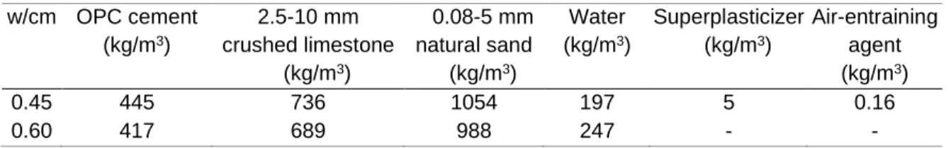
6.4.1 Materials and Mixture Proportions ... 87
6.4.2 Restrained Shrinkage Ring Test ... 90
vii
6.4.4 Weight Loss ... 92
6.4.5 Characterization of the Shotcrete ... 92
6.5 Test results and discussion ... 93
6.5.1 Fresh Properties of Dry-mix Shotcrete ... 93
6.5.2 Hardened Properties of Dry-mix Shotcrete ... 97
6.5.3 Shrinkage Test Results ... 101
6.5.4 Weight Loss ... 105
6.5.5 Shrinkage-induced Stress Development in the Restrained Ring Specimens ... 105
6.6 Conclusions ... 114
6.7 Acknowledgments ... 115
Chapter 7 Article 5 - Evaluation of Early-age Viscoelastic Characteristics of Shotcrete Using Ring Specimens... 116
7.1 Résumé ... 116
7.2 Abstract ... 116
7.3 Introduction ... 117
7.3.1 Research Significance ... 118
7.4 Determining Tensile Creep and Relaxation from Ring Specimen Measurements ... 119
7.4.1 Quantifying Tensile Creep of Concrete Using Ring Specimen ... 119
7.4.2 Quantifying Stress Relaxation Using Ring Specimen ... 121
7.5 Experimental Program ... 121
7.5.1 Materials and Mixture Proportions ... 122
7.5.2 Placement methods ... 123
7.5.3 Restrained Ring Test Specimens ... 123
7.5.4 Free Ring Test Specimens ... 125
7.5.5 Mechanical characterization ... 125
7.6 Test Results ... 126
7.7 Discussion of Test Results ... 129
7.7.1 Influence of concrete creep and relaxation in the ring stress build-up and cracking outcome .... 129
7.7.2 Cracking of restrained concrete ... 136
7.8 Conclusion ... 139
7.9 Acknowledgments ... 140
Chapter 8 Discussion of Test Results ... 141
8.1 Introduction ... 141
8.2 Influence of Specimen Geometry and Boundary Conditions ... 141
8.3 Influence of Key Mixture Parameters ... 142
8.3.1 Influence of Cement Content ... 142
viii
8.3.3 Effect of Silica Fume ... 143
8.3.4 Effect of Fly Ash ... 144
8.3.5 Effect of Polymer ... 145
8.3.6 Effect of Shrinkage-Reducing Admixture (SRA) ... 145
8.3.7 Effect of Crack-Reducing Admixture (CRA) ... 145
8.3.8 Effect of w/cm Ratio ... 146
8.4 Effect of Curing Method and Curing Periods ... 147
8.5 Influence of Method of Placement ... 147
8.6 Conclusion ... 149
Summary and Conclusions ... 150
Summary ... 150
Conclusions ... 150
Perspectives for Future Research ... 152
Experimental Investigation ... 152
Numerical Modelling ... 153
References ... 154
Appendix A Article 6 - Évaluation de la Sensibilité et Potentiel à la Fissuration des Bétons Projetés au Jeune Âge ... 160
A.1 Abstract ... 160
A.2 Résume ... 160
A.3 Introduction ... 161
A.4 Campagne expérimentale ... 162
A.4.1 Composition des mélanges ... 162
A.5 Procédure des essais ... 162
A.5.1 Essais de retrait libre ... 163
A.5.2 Essais de retrait restreint ... 163
A.6 Modélisation numérique ... 163
A.7 Résultats et discussion ... 166
A.7.1 Retrait libre: ASTM C157 et annulaire ... 166
A.7.2 Sensibilité à la fissuration du béton projeté ... 167
A.8 Conclusions ... 169
A.9 Remerciements ... 169
A.10 Références ... 170
Appendix B Mixture Constituents ... 171
Appendix C Supplementary Test Data ... 179
ix
List of Tables
Table 3.1 Composition of the investigated concrete mixtures ... 39
Table 3.2 Dimensions and S/V ratios of specimens ... 40
Table 3.3 Mechanical properties ... 43
Table 4.1 Concrete mixtures investigated ... 54
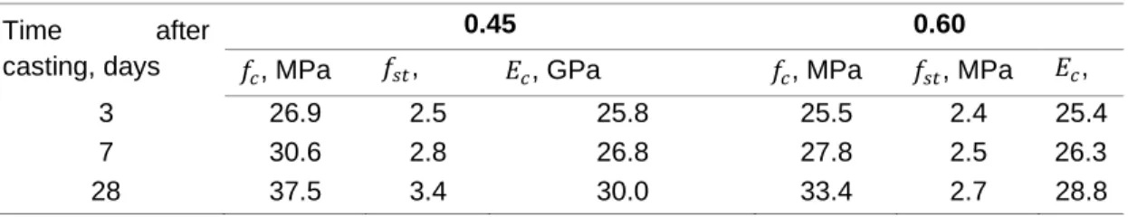
Table 4.2 Compressive strength, tensile strength, and modulus of elasticity data ... 60
Table 4.3 Suggested cracking potential classification (Based on stress rate at cracking) ... 67
Table 5.1 28-day compressive strength test results ... 75
Table 5.2 28-day boiled water absorption test results ... 76
Table 6.1 Compositions of shotcrete mixtures investigated - Phase I ... 90
Table 6.2 Compositions of shotcrete mixtures investigated - Phase II ... 90
Table 6.3 Compositions of shotcrete mixtures investigated - Phase III ... 90
Table 6.4 Characterization of fresh dry-mix shotcrete mixtures investigated ... 96
Table 6.5 Shotcrete quality control indicators ... 97
Table 6.6 Compressive strength of the mixtures tested (unit: MPa) ... 99
Table 6.7 Suggested cracking potential classification. (Based on stress rate at cracking) ... 113
Table 6.8 Suggested cracking potential classification. (Based on stress rate at 7 days after initiation of drying) ... 113
Table 7.1 Composition of the wet-mix shotcretes mixtures investigated ... 122
Table 7.2 Composition of the dry-mix shotcretes mixtures investigated ... 123
Table 7.3 Mechanical properties of the hardened wet-mix shotcretes ... 126
Table 7.4 W/cm ratio and mechanical properties of the hardened dry-mix shotcretes... 126
Tableau A.1 Compositions des mélanges coulés en place ... 162
x
List of Figures
Fig. 1.1 Typical setup for a) dry-mix shotcrete operations; b) wet-mix shotcrete operations ... 7 Fig. 1.2 Rebound as a function of the shooting consistency of the mixture [8] ... 8 Fig. 1.3 Time dependence of cracking on restrained shrinkage and creep/relaxation ... 15 Fig. 1.4 (a) Influence of water-cement ratio and aggregate content on total shrinkage [17]; (b) effect of
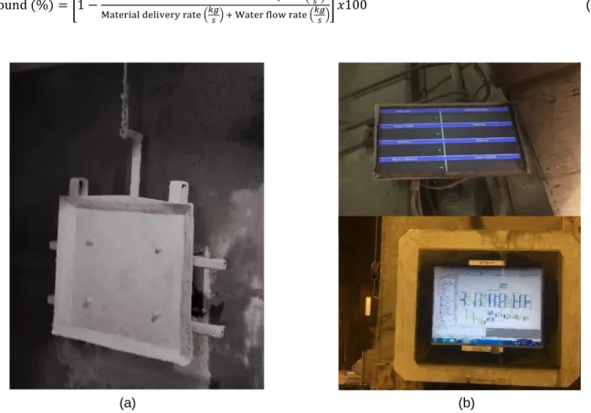
paste content on shrinkage [36]... 18 Fig. 1.5 Influence of silica fume addition on autogenous shrinkage [45] ... 18 Fig. 1.6 Test specimen configuration for free shrinkage ring test based on the AAHTO ring test setup .... 21 Fig. 1.7 Test specimen configuration for shrinkage cracking tendency test (AASHTO ring test setup) ... 23 Fig. 2.1 (a) Aliva® 246 dry-mix shotcreting machine, (b) spirolet nozzle mounted on pre-wetting lance and (c) double bubble nozzle tip used in this study ... 28 Fig. 2.2 Typical setup for rebound measurement: (a) instrumented vertical shotcrete test panel; (b) data
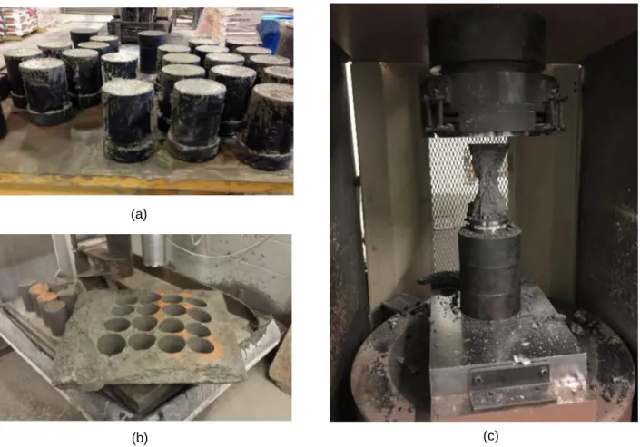
acquisition system linked to a computer for display, controls and logging ... 29 Fig. 2.3 Specimen for the characterization of mechanical properties: (a) cast cylinder samples, (b)
sprayed test panel and cored samples, and (c) test specimen in compression ... 30 Fig. 2.4 ASTM C157 test specimens: (a) gravity-cast specimens and (b) spray-cast specimens ... 31 Fig. 2.5 Free ring shrinkage test: a) mold prior to casting; and b) test specimen with outer steel ring and
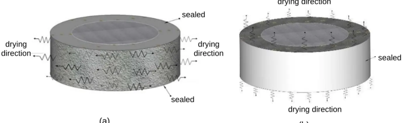
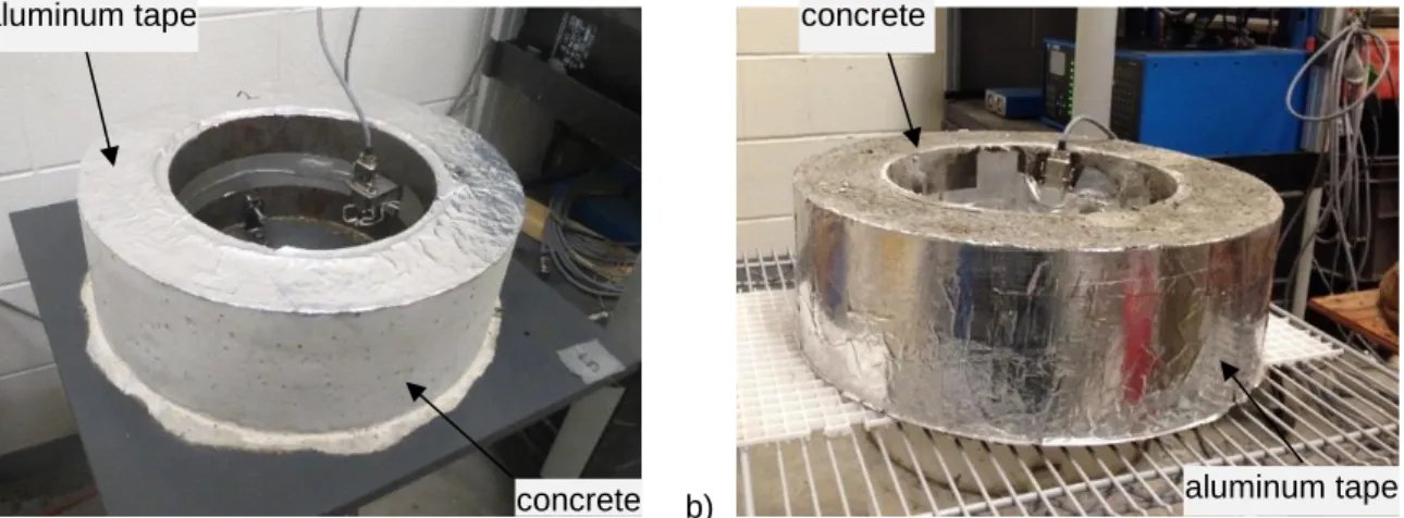
inner polystyrene insert, immediately after spray-casting ... 32 Fig. 2.6 Free ring specimen with DEMEC gauges: a) sealed on top (and bottom) for radial drying; and b)
sealed on the outer circumferential surface for axial drying ... 32 Fig. 2.7 Ring specimen with inner steel ring and outer PVC, immediately after gravity-casting; and b) after
removal of the outer PVC form ... 33 Fig. 2.8 Sprayed specimen with: (a) inner and outer steel ring, immediately after spraying; and (b) after
removal of the steel ring ... 34 Fig. 2.9 Restrained ring specimen: a) sealed on top and bottom for radial drying; and b) sealed on the
outer circumferential surface for axial drying ... 34 Fig. 3.1 Dimensions of free ring setup (radial drying condition illustrated). (a) Top view. (b) Front view ... 38 Fig. 3.2 ASTM C157 specimens ... 40 Fig. 3.3 Template for positioning of the DEMEC point discs on the free ring-shape specimens ... 41 Fig. 3.4 Free ring specimen with DEMEC: (a) Sealed on top (and bottom) and (b) sealed on the outer
circumferential surface ... 42 Fig. 3.5 Compressive strength of concrete (error bars represent the coefficient of variation) ... 43 Fig. 3.6 ASTM C157 modified shrinkage strain results obtained under various drying exposure conditions. (a) w/cm 0.45 mixture, (b) w/cm 0.60 mixture ... 44
xi
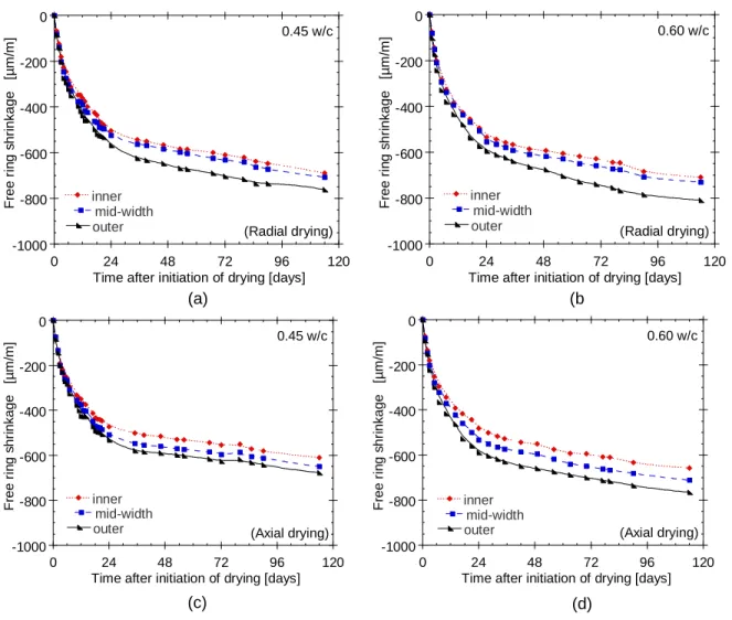
Fig. 3.7 The influence of DEMEC gauge positioning on the measured free ring shrinkage strain: (a) w/cm 0.45 radial drying specimen, (b) w/cm 0.60 radial drying specimen, (c) w/cm 0.45 axial drying
specimen, (d) w/cm 0.60 axial drying specimen ... 45
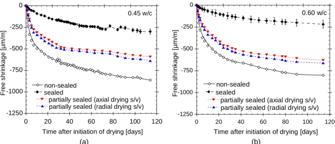
Fig. 3.8 Influence of specimen geometry, S/V and drying direction on free shrinkage recorded: (a) w/cm 0.45 mixture, (b) w/cm 0.60 ... 47
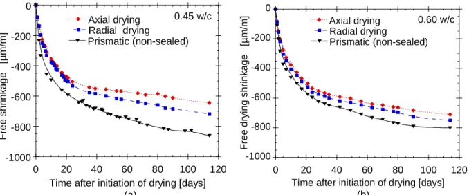
Fig. 3.9 Free shrinkage recorded on prismatic and ring specimens with equal S/V ratio: (a) w/cm 0.45 radial drying specimen, (b) w/cm 0.60 radial drying specimen, (c) w/cm 0.45 axial drying specimen, (d) w/cm 0.60 axial drying specimen ... 48
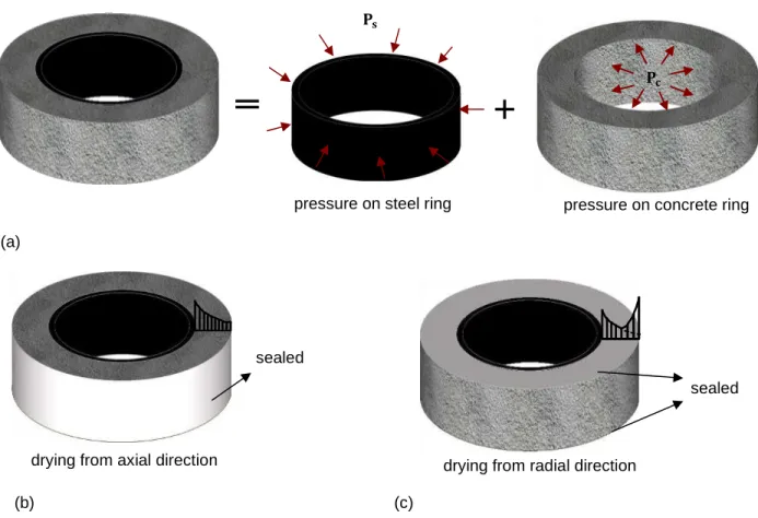
Fig. 4.1 Ring test setup used in the AASHTO T334-08 ring test ... 55
Fig. 4.2 AASHTO T334-08 ring test specimens sealed a) on top and bottom faces (i.e. radial drying), and b) on the outer circumferential face (i.e. axial drying) ... 55
Fig. 4.3 Schematical illustration of (a) contact pressure acting in the steel ring and the concrete ring, (b) stress profile when drying from axial direction, and (c) stress profile when drying from radial direction ... 57
Fig. 4.4 Schematical illustration of the internal forces developing in the rings ... 58
Fig. 4.5 Free shrinkage test results from companion ring specimens subjected to a) radial drying; b) axial drying ... 61
Fig. 4.6 Free shrinkage test results from companion ring specimens – strain rate factors ... 62
Fig. 4.7 AASHTO T334 restrained shrinkage test results – 0.42 w/cm mixture ... 63
Fig. 4.8 AASHTO T334 ring test results – influence of drying conditions ... 65
Fig. 4.9 Age at (visible) cracking of restrained ring specimens ... 65
Fig. 4.10 AASHTO T334 ring test results – strain and stress rates ... 67
Fig. 4.11 Cracking observed in restrained ring specimen (0.45 w/cm mixture) ... 68
Fig. 5.1 Shrinkage test specimens: a) spraying process; b) testing layout ... 73
Fig. 5.2 Shotcrete test panels a) during shotcreting; b) subjected to air and sealed curing ... 74
Fig. 5.3 ASTM C642 volume of permeable void results – standard VPV test ... 77
Fig. 5.4 ASTM C642 volume of permeable void results – modified VPV test for the two slices A and B ... 77
Fig. 5.5 ASTM C157 test results of the tested shotcrete mixtures submitted to different curing regimes .. 79
Fig. 5.6 Drying shrinkage of the tested concrete submitted to different curing regimes ... 79
Fig. 5.7 Strain rate factors determined from ASTM C157 length change data of concrete submitted to different curing regimes, after the specimens were exposed to drying ... 80
Fig. 5.8 Weight change of recorded in the ASTM C157 test specimens submitted to different curing regimes, from the time of demolding ... 81
Fig. 5.9 Weight change of recorded in the ASTM C157 test specimens submitted to different curing regimes, from the time of drying ... 82
xii
Fig. 6.2 (a) Aliva®-246 dry-mix shotcrete machine, (b) typical hydomix nozzle assembly with water ring
1.5 m before exit and (c) double bubble nozzle tip used in this study ... 89
Fig. 6.3 Inclined overhead setup used to spray the shotcrete ring test specimens; (a) setup before spraying, (b) setup after spraying, (c) sealed instrumented restrained ring specimens, and (d) free ring specimens ... 91
Fig. 6.4 Shotcrete test panel (left) and cored samples (right) ... 93
Fig. 6.5 Rebound calculated for the tested mixtures ... 94
Fig. 6.6 Effect of chemical admixtures on the splitting tensile strength ... 100
Fig. 6.7 Results of the elastic modulus test ... 101
Fig. 6.8 Total free shrinkage of the tested dry-mix shotcrete mixtures ... 103
Fig. 6.9 Free shrinkage strain rate factors determined from free ring specimen length change data ... 104
Fig. 6.10 Total percentage of weight loss of the tested dry-mix shotcretes ... 105
Fig. 6.11 Effect of mixture parameters on shrinkage cracking of the tested dry-mix shotcrete mixtures . 108 Fig. 6.12 Cracking age of restrained shotcrete ... 110
Fig. 6.13 Stress rate at age of cracking of the mixtures tested ... 112
Fig. 7.1 Conceptual illustration of concrete strain components ... 121
Fig. 7.2 AASHTO T334-08 ring test specimens: a) cast ring specimen with outer PVC wall (before demolding); b) demolded cast ring specimen at 24 h; c) inclined overhead sprayed ring specimen with outer steel wall (before demolding); and d) sprayed demolded ring specimen at 24 h ... 124
Fig. 7.3 Evolution of free and restrained ring shrinkage of the wet-mix shotcretes in radial drying configuration ... 128
Fig. 7.4 Evolution of free and restrained ring shrinkage of the wet-mix shotcretes in axial drying configuration ... 128
Fig. 7.5 Evolution of free and restrained ring shrinkage of the dry-mix shotcretes with 15% coarse aggregates ... 129
Fig. 7.6 Evolution of free and restrained ring shrinkage of the dry-mix shotcretes with 24% coarse aggregates ... 129
Fig. 7.7 Tensile creep data of the wet-mix shotcretes from the ring tests - evolution of the specific creep deformations ... 131
Fig. 7.8 Tensile creep data of the dry-mix shotcretes from the ring tests - evolution of the specific creep deformations ... 131
Fig. 7.9 Tensile creep data of the wet-mix shotcretes from the ring tests - evolution of the creep coefficients ... 132
Fig. 7.10 Tensile creep data of the dry-mix shotcretes from the ring tests - evolution of the creep coefficients ... 133
Fig. 7.11 Tensile creep data of the wet-mix shotcretes from the ring tests - evolution of the total creep deformations ... 133
xiii
Fig. 7.12 Tensile creep data of the dry-mix shotcretes from the ring tests - evolution of the total creep deformations ... 134 Fig. 7.13 Evolution of the tensile creep strain-to-shrinkage ratio of the wet-mix shotcretes in the ring
experiments ... 135 Fig. 7.14 Evolution of the tensile creep strain-to-shrinkage ratio of the dry-mix shotcretes in the ring
experiments ... 135 Fig. 7.15 Evolution of the tensile stress relaxation versus drying time of the wet-mix shotcretes in the ring
tests ... 136 Fig. 7.16 Evolution of the tensile stress relaxation versus drying time of the dry-mix shotcretes in the ring
tests ... 136 Fig. 7.17 Evolution of the stress-strength ratio of the wet-mix shotcretes in the ring experiments ... 137 Fig. 7.18 Evolution of the stress-strength ratio of the dry-mix shotcretes in the ring experiments ... 137 Fig. 7.19 Tensile creep data of the wet-mix shotcretes from the ring experiments - relationship between
the creep strain and the stress-strength ratio ... 138 Fig. 7.20 Tensile creep data of the dry-mix shotcretes from the ring experiments - relationship between
the creep strain and the stress-strength ratio ... 139
Fig. A.1 Évolution de la résistance à la compression ... 164 Fig. A.2 Évolution du libre retrait sur prisme après 3 et 7 jours de mûrissement à 100% H.R. (t0= 3d et
7d): Comparaison des résultats expérimentaux et de la modélisation - Cas du béton coulé en place ... 166 Fig. A.3 Évolution du retrait libre sur anneau après 3 jours de mûrissement à 100% H.R.: comparaison
des résultats expérimentaux et de la modélisation - Cas du béton coulé en place et projeté. ... 167 Fig. A.4 Évolution de la contrainte moyenne après 3 jours de mûrissement à 100 % H.R. : comparaison
des résultats expérimentaux et de la modélisation - Cas du béton coulé en place. ... 168 Fig. A.5 Évolution de la contrainte moyenne après 3 jours de mûrissement à 100 % H.R. : comparaison
des résultats expérimentaux et de la modélisation - Cas du béton projeté par voie sèche. ... 168 Fig. A.6 Patron des fissurations expérimental (a) et numérique (b) après 3 jours de cure ... 169
xiv
xv
Acknowledgment
I would like to thank everyone that contributed and helped make this dissertation possible. First, my deepest gratitude goes to my supervisor Prof Marc Jolin and co-supervisor Prof Benoît Bissonnette for their advice, guidance, and complete support of my personal and professional development. Their constructive criticisms, effective discussions and suggestions greatly helped me to complete my work successfully. I would also like to thank my ad-hoc co-supervisor Dr Laurent Molez for his advice, guidance, and help in understanding modelling of concrete early age behaviour.
I am also indebted to Mr Jean-Daniel Lemay and Mr Mathieu Thomassin for their outstanding technical support. Their help and experience have been essential to this dissertation and to my development. I would also like to thank Mr. Alexandre Pépin Beaudet for all his help and devotion in the spraying aspect of this project. Working with Samy-Joseph Essalik has made my time at the Université Laval a truly memorable experience. Thanks to my colleagues Pasquale Basso-Trujillo, Antoine Gagnon, and Thomas Jacob Vaillancourt. My sincere gratitude also goes to all the administrative staffs, especially Lyne Dupuis for her kindness and help.
Special thanks to my family and love ones for all their love, support, and encouragement throughout my life to this point. Without their guidance and encouragement, this work and everything it entails would have been impossible. I will always be grateful for everything they have done and owe them a debt that can never be repaid.
xvi
Preface
This research project is intended to accomplish a comprehensive study on the shrinkage and the associated potential for cracking of shotcrete mixtures by evaluating their early age shrinkage and tensile creep properties. This Ph.D. dissertation is written as an article-based thesis and consists of five research papers (main body) and one scientific conference paper (appendix). The author of this dissertation is the main author of all of the above-mentioned articles. The contributions of the first author to the articles consisted of carrying out the research works, gathering the results, doing the analyses, writing the computer codes, plotting the graphs, drafting, and revising of the articles. Co-authors Dr. M. Jolin and Dr. B. Bissonnette supervised the research work, improved the methods of interpretation of the results and the research methodology, and critically revised the papers. Co-author Dr. L. Molez supervised the writing of the computer codes, analysis and interpretation of data, and critically revised the papers, Co-authors Mr. A. Pepin- Beaudet and Mr. T. Jacob-Vaillancourt participated in the experimental work, acquisition of data and initial drafting of articles during their M.Sc. work.
The layout of the articles was revised extensively to reflect imposed the Ph.D. dissertations. Also, for the sake of uniformity, the same citations style was used for all the articles presented in the dissertation.
1
Introduction
A brief insight of the problem at hand and the objective of this thesis are provided in this chapter. This will include brief review of previous research efforts to reduce the shrinkage and, ultimately, the cracking tendency of concrete and/or shotcrete mixtures.
Background
The motivation for this project is the effort to reduce the cracking potential of shotcrete, notably in view of repair applications. Shotcrete has proven to be an advantageous technique for concrete repairs, and with the ever-increasing need for concrete infrastructure rehabilitation and the solid technological background available today, this application technique is in great demand. A great majority of shotcrete repairs have performed satisfactorily over the past years. However, extensive shrinkage cracking is still encountered in some situations, eventually leading to debonding, premature deterioration and failures of shotcrete repairs in service. Early age cracking of repairs is a major concern of the shotcrete repair industry. Cracking is caused mainly by restraint to volume changes resulting from dimensional incompatibility between the repair material and the substrate. The new concrete (repair material) seeks to shrink freely, whereas the old existing concrete in the structure being repaired (substrate) is in a more stable volumetric state. Through adhesion, the repair concrete is prevented from contracting by the old concrete, resulting in the development of internal tensile stresses. If the induced stresses exceed the tensile strength of the repair material, cracks will appear. The likelihood of cracking depends largely on the rate of development of strength (tensile), elastic modulus and creep properties in the repair material, with respect to the existing substrate properties.
Research Objectives
The ultimate goal of this PhD thesis is to gain a better and more up-to-date understanding of the shrinkage and cracking sensitivity of shotcrete. The project seeks to help formulate guidelines that can be employed to predict the likelihood of restrained shrinkage cracking occurrence in shotcrete applications. The improved knowledge from the project will help engineers develop and use repair shotcrete with significantly low sensitivity to shrinkage cracking. Following a review of the information available today, the specific objectives will be reached by focusing mainly on the following:
- Optimize the free ring shrinkage test procedure and correlate the results with the restrained ring test results;
- Correlate the cracking potential with mixture proportions and mechanical properties;
- Investigate the key mix design parameters that influence shrinkage and the cracking behaviour of shotcrete;
2
- Explore the influence of the placement method (i.e., cast-in-place and sprayed) on shrinkage and the cracking characteristics of shotcrete;
- Develop a numerical tool for the study of the shrinkage and the cracking potential of shotcrete mixtures; In parallel, two supplementary specific objectives were naturally linked to this work:
- Explore the effect of curing and protection on shrinkage and the quality of the in-place shotcrete (M.Sc. project of Jacob-Vaillancourt running in parallel);
- Evaluate the significance of the shrinkage ring tests (restrained and unrestrained) as suitable tools for characterizing the sensibility to cracking of repair materials (M.Sc. project of Alexandre Pépin-Beaudet running in parallel).
The originality of this project is the focus on characterizing key factors that lead to cracking of shotcrete through the use of free and restrained shrinkage tests. Moreover, the data will provide sufficient information on the cracking potential of mixtures that will lead to the optimization and improvement of shotcrete mixture designs with reduced sensitivity to cracking.
Previous Works (CRIB, Université Laval)
The problem of shrinkage and cracking of concrete and/or shotcrete has already been the subject of several master's and doctoral thesis at the CRIB (Research Centre on Concrete Infrastructure) of Université Laval. Most notably, Bissonnette (1996) [1] and Modjabi-Sangnier (2010) [2]) has shown that the cracking potential of a concrete mixture cannot be solely weighed by the amplitude of its drying shrinkage because of stress relaxation due to tensile creep. These results demonstrated the importance of considering tensile creep in predicting the risk of cracking, particularly in repairs. The results further showed that concrete tensile creep potential is mostly dependent on certain mixture parameters.
In a subsequent experimental program led by Girard [3], the AASHTO shrinkage ring test procedure (AASHTO T334-08 [4], formerly AASHTO PP 34–99 [5]) was used as a basis towards the development of an approach for the quantitative assessment of dimensional compatibility and sensitivity to cracking of
shotcrete. The results of the study showed that the modified procedure to cast the AASHTO ring test
specimen through pneumatic projection can be used successfully to evaluate the sensitivity to cracking of shotcrete mixtures. Although this test method has only been used at Université Laval’s shotcrete laboratory up to now, it is the aim of this thesis work to further improve the proposed approach proposed and help eventually develop it into a standardized testing method.
Previous research works (such as reference [2, 3]) attempted to combine the free shrinkage ring measurements and restrained ring shrinkage results to perform analytical viscoelastic calculations, but the approach was not conclusive. The calculated creep values calculated from these data were found to be variable and sometimes inconsistent. The current study will thus intend to investigate the cause of the inconsistencies. This will in addition provide a better understanding of the difference between the measured
3
free ring shrinkage and that obtained from a uniaxial shrinkage test (particularly with the same volume/surface ratio exposed to drying) and allow to assess the necessity to use the former in restrained shrinkage investigations involving ring specimens.
Organization of Contents
This Ph.D. dissertation is written as an article-based thesis. The thesis begins with an introduction which includes a background, research objectives and structure of the thesis. Chapter 1 provides an up-to-date account of the present state of knowledge on shotcrete technology and on early-age shrinkage and cracking. Some techniques used in mitigating shrinkage of shotcrete are also highlighted. Chapter 2
provides an overview of the materials used and the detailed experimental programs outlined to address the issues of shrinkage and the associated potential risk of cracking of shotcrete. Chapters 3 to 7 contains the main research findings of the thesis which are presented through five research papers either published or submitted for publication in recognized scientific journal. A supplementary paper presented in a renowned scientific conference is found in Appendix A. Chapter 8 presents a discussion of the results compiled from the different papers. The dissertation is completed by a summary and a conclusion of the overall research, along with some possible future research avenues. The research papers included in this Ph.D. thesis are as follows.
Chapter 3 Article #1 pp 36 - 49
B. Menu, M. Jolin, and B. Bissonnette. 2017. Studies on the influence of drying shrinkage test procedure,
specimen geometry, and boundary conditions on free shrinkage, published in Advances in Materials
Science and Engineering, Article ID 9834159.
The paper describes the research that has been carried out to optimize the free ring shrinkage test procedure. The study demonstrates the influence of the free shrinkage test procedure, the specimen geometry, the boundary conditions, and the surface area-to-volume ratio exposed to drying on the free shrinkage of shotcrete.
Chapter 4 Article #2 pp 50 - 69
B. Menu, M. Jolin, and B. Bissonnette. 2020. Assessing the early-age shrinkage cracking potential of
concrete using ring specimens under different boundary conditions published in Advances in Materials
Science and Engineering, Article ID 4842369.
This paper deals with the potential for cracking due to restraints and is a continuation of the previous paper on free shrinkage. The paper presents information to improve our interpretation of cracking behaviour in
4
of the concrete rings. The findings are used to provide guidance towards the implementation of a suitable drying method for shotcrete ring tests.
Chapter 5 Article #3 pp 70 - 82
B. Menu, T. Jacob-Vaillancourt, M. Jolin, and B. Bissonnette. July 2020. The role of curing methods in
early age moisture loss and drying shrinkage, published in ACI Materials Journal, V. 117, No. 4.
It was shown in article #2 that longer moist curing can delay shrinkage and counteract the risk of early-age cracking. This paper is an extended research to investigate the effectiveness of the most commonly used curing methods on early-age water evaporation and the subsequent shrinkage in freshly applied shotcrete. Among the range of curing methods investigated, moist curing performed better. Dry curing was found to be the least effective and most detrimental, while effectiveness of curing compound was found to be dependent on the w/cm ratio, being less efficient in low w/cm ratio mixture, but beneficial in higher w/cm ratio concrete.
Chapter 6 Article #4 pp 83 - 115
B. Menu, A. Pepin- Beaudet, M. Jolin, and B. Bissonnette. Experimental study on the effect of mixture
parameters on shrinkage and cracking resistance of dry-mix shotcrete, submitted to Cement and
Concrete Composites on September 28, 2020.
While previous articles focused on the influence of specimen geometry, drying layout and curing on shrinkage and cracking of shotcrete. This paper reports results of an experimental study conducted to investigate the influence of key mixture parameters on shrinkage, stress development, and age at cracking of dry-mix shotcrete mixtures using the ring shrinkage test method. In this study, for the first time, an investigation was initiated on the use of crack-reducing admixture in dry-mix shotcrete mixtures. The investigation showed that the addition of silica fume or combine silica fume and fly ash increases the cracking potential of the dry-mix shotcrete, whereas the use polymer, shrinkage-reducing admixture or crack-reducing admixture reduces it. This study also confirms that it is possible to produce shotcrete ring specimens that comply with the AASHTO T 334 ring test standard.
Chapter 7 Article #5 pp 116 - 140
B. Menu, B. Bissonnette and M. Jolin, . Evaluation of early-age viscoelastic characteristics of concrete
using ring specimens, submitted to Journal of Materials in Civil Engineering on October 26, 2020.
This paper illustrates how free shrinkage ring and restrained ring shrinkage measurements from the previous papers can provide data on the tensile creep and relaxation behaviour of different shotcrete mixtures. It was found that mixtures with a higher level of creep or relaxation and lower shrinkage exhibited
5
lower risk of shrinkage cracking in otherwise equal conditions. This indicates that higher tensile creep capacity is only useful in reducing the risk for cracking if the shrinkage is not increased in the same proportion. The study also demonstrated that tensile creep is an essential component in the evaluation of the risk and sensitivity to cracking of shotcrete under restrained conditions.
As complement to the publications mentioned above, a publication on numerical modelling of shotcrete is presented in Appendix A.
Appendix A Article #6 pp 160 - 169
B. Menu, M. Jolin, B. Bissonnette, and L. Molez. 2018. Évaluation de la sensibilité et potentiel à la
fissuration des bétons projetés au jeune âge, published in proceeding of the Conférence Internationale Francophone NoMaD 2018, Liège Université, Liège, Belgique, p. 9.
The present paper is intended to give an overview of the numerical method developed to analyze the behaviour of concrete ring specimens under free and restrained shrinkage. The proposed model and the identified materials parameters validated were used to simulate the shrinkage cracking behaviour of selected shotcretes mixtures from previous papers. It has been found that numerical results agree well with experimental results in terms of cracking ages for both cast and sprayed rings, indicating that the proposed numerical approach is reliable for analyzing cracking in concrete ring specimens subject to restrained shrinkage.
Some additional publications have been made during the project (not presented here). These publications are:
B. Menu, M. Jolin, B. Bissonnette, and N. Ginouse. June 2017. Evaluation of early age shrinkage
cracking tendency of concrete, Proceedings of the CSCE Annual Conference on Leadership in Sustainable Infrastructure, Vancouver, Canada, pp. EMM649-1-EMM649-8.
B. Menu, Pépin Beaudet, M. Jolin, B. Bissonnette, and L. Molez. 2018. Évaluation quantitative de la
sensibilité à la fissuration du béton au moyen de l'essai de retrait restreint annulaire, in 19ème Journées Scientifiques du Regroupement Francophone pour la Recherche et la Formation sur le Béton ((RF)²B), Anglet, France, 10 pages.
6
Chapter 1 Literature Review
1.1 Introduction
This chapter provides an up-to-date account of the present state of knowledge on shotcrete and its deformational properties. This will include a general description and insight into shotcrete technology and what renders shotcrete susceptible to cracking due to shrinkage cracking. Other phenomena and factors that need to be considered in analyzing restrained shrinkage cracking is also discussed and basic terms will be defined. To avoid repetition, this chapter will only focus on specific issues since elements of the literature review are also presented in the various articles.
1.2 Shotcrete Technology
Researchers, engineers, construction managers, developers, and architects have tried over the years to enhance and introduce more efficient concrete placement and construction methods, with the aim of reducing the costs and turnaround time. This led to the introduction of a special type of concreting method known as shotcrete (also known as sprayed concrete in many parts of the world). Shotcrete was first introduced into the construction industry in 1910 [6]. Since its inception, shotcrete applications have expanded consistently, with constant improvements and innovations of the technique and mixture design. Today, shotcrete is receiving more attention in almost all domains of the construction industry. In fact, shotcrete has become an indispensable tool in the repair and rehabilitation of concrete structures. The mining and tunnelling industries are other major users of shotcrete, especially for ground stabilization as a temporary support or final lining. Shotcrete technology has also grown into an important technique wherever irregular and complex geometries are involved. Further, the time needed for shotcreting works is much
faster, making it very attractive in construction projects where scheduling is critical.
Shotcrete is a mortar or concrete that is pneumatically sprayed or projected at high velocity through a pressure resistant conveying hose onto a surface, where it is compacted on impact. Thus, the high velocity is essential for the shotcrete process as it allows the material to stick to the sprayed surface and ensures adequate compaction or consolidation and allows the material to stick to the sprayed surface. Without a proper compaction and consolidation, quality shotcrete cannot be produced [7]. Adequate in-place shotcrete is well-compacted and free of cracks, and it encapsulates the reinforcement and adheres well to the receiving substrate.
1.2.1 Why not Shotcrete?
There is often a debate on how exactly shotcrete differs from ordinary cast-in-place concrete. In reality, shotcrete is unique in some respects: it has its own mixture designs, its own implementation techniques, its own testing and recommendations. Notwithstanding, shotcrete simply remains a method for placing
7
concrete or mortar. In fact, if properly applied, the durability and physical properties of shotcrete are comparable to those of conventional cast-in-place concrete of similar composition. In most cases, the shotcrete placement method provides a significant number of advantages in wide areas of applications where normal cast-in-place techniques cannot be employed, for instance where access to the work area is difficult and where thin layers or variable thicknesses are required.
Shotcrete is also useful in situations where formwork is not expensive or not practical, and it can offer savings on labour. In the case of repairs, shotcrete can provide superior durability and bonding to existing concrete. The many pros and cons of shotcrete are covered elsewhere [6, 8, 9].
1.2.2 Shotcrete Process
Shotcrete can be produced using two different techniques, the wet-mix and the dry-mix processes. Be it the wet-mix or the dry-mix process, the shotcrete material is conveyed through a hose and then projected onto a surface. The major differences between the two processes have to do with the method of conveying the material through the hose and the location where water is added to the mixture. A schematic set-up of both shotcreting processes is presented in Fig. 1.1. The most widely used method in repairs is the dry-mix process, where the dry materials are conveyed through the delivery hose and wetted at the water ring before exiting at the nozzle. The dry materials may be prebagged or mixed on site. The wet-mix process involves the mixing of all of the ingredients (except for certain admixtures) before they enter the delivery hose. Thus, all mixing water is present in the concrete before its introduction into the pump for the wet-mix shotcrete; while for the dry-mix shotcrete process, water is introduced near the end of the delivery hose [8]. Today, the trend towards automated or remote-controlled spraying equipment for shotcreting is gaining grounds, especially in the mining and tunnelling sector. Nevertheless, shotcrete mix produced with conventional batching equipment and applied from a hand-held nozzle remains and still is the most common and widely used method for repairs.
Fig. 1.1 Typical setup for a) dry-mix shotcrete operations; b) wet-mix shotcrete operations Nozzleman Air compressor Reinforcing steel Nozzle Shotcrete materials Water supply Pre-dampener Shotcrete gun (a) Nozzleman Air compressor Reinforcing steel Nozzle Concrete truck Concrete pump (b)
8
1.2.2.1 Consistency
In the dry-mix process, the nozzleman has control over mixing water and thus of the consistency of the mixture at the nozzle to meet variable field conditions whereas in the wet-mix process, the mixing water is controlled at the mixing equipment [9, 10]. The consistency (i.e., degree of wetness or plasticity) of an in-place shotcrete is of utmost importance as it may affect both its strength and shrinkage properties. Shotcrete with a relatively dry (stiff) shooting consistency may adversely affect rebar encapsulation as well as increase rebound [11]. As clearly shown in Fig. 1.2, the amount of material rebound varies linearly with the shooting consistency for a given shotcrete mixture. Reportedly, spraying the dry-mix shotcrete at its so-called wettest stable consistency helps minimizing rebound losses and most importantly, allows proper encasement of the reinforcing steel [8]. To ensure comparability among mixtures with different compositions, a consistency criterion may be set, for which the nozzleman is allowed to adjust the water flow (as opposed to equal w/cm ratio in conventional concrete) [12].
Shooting consistency (MPa)
O ve ral l R eb on d 20% 25% 30% 35% 40% 45% 50% 55% 0.0 0.5 1.0 1.5 2.0 2.5 3.0 3.5 4.0 OPC Shotcrete
OPC + Silica fume shotcrete
"dry" or "stiff" shotcrete "soft" shotcrete
Fig. 1.2 Rebound as a function of the shooting consistency of the mixture [8]
1.2.2.2 Rebound
A very distinctive aspect of shotcrete is that a certain portion of the materials misses the target or does not adhere to the surface during spraying. The amount of materials bouncing off the receiving surface is known as rebound. Rebound is perhaps one of the biggest challenges facing the shotcrete industry today. How much rebound is acceptable for a shotcrete application is not entirely clear, but it is desired to minimize rebound. Generally, the dry-mix process produces greater rebound losses than the wet-mix process. The amount of rebound by weight of total sprayed materials is generally in the range of 5 to 15% for the wet-mix process [6, 8] and 15 to 40% for the dry-mix process [8, 12, 13]. How much is acceptable for a given shotcrete application may vary, but it is desirable to minimize rebound. Unfortunately, rebound in shotcrete
9
is not only expected but is inevitable and to a certain extent. For example, aggregates bouncing off the surface may create a sticky surface for subsequent shotcrete material to become compacted into the surface [13]. Thus, some rebound is necessary to achieve the needed consolidation and desired properties of the shotcrete.
Nevertheless, it must be emphasized that rebound affects the final in-place mixture composition by reducing the amount of coarse aggregate and consequently, the as-shot mechanical properties. Furthermore, rebound also has a major economical consequence on the final construction cost. More importantly, shotcrete often exhibits higher shrinkage tendency in comparison with ordinary concrete due to rebound. This is primarily because a high proportion of the rebounding materials corresponds to the coarse aggregates which play key roles in opposing shrinkage of concrete and diluting the paste content. Many factors related to the shooting parameters (air velocity, shooting angle, orientation, and thickness of shooting) and mix design proportion parameters (e.g. cement, silica fume, set accelerator, and water content) will affect the overall rebound [6, 13]. As can be seen in Fig. 1.2, silica fume as well as the shooting consistency (water content) influence shotcrete rebound.
1.2.3 Cementitious Materials
Like any other ordinary concrete, pozzolanic materials such as slag, fly ash and silica fume are often incorporated into shotcrete mixtures. Silica fume, a highly pozzolanic mineral additives is added at a typical dosage of about 5 to 10% by weight of cement to produce superior quality shotcrete as it improves the cohesion and adhesion of shotcrete mixture. In addition, adding silica fume also reduces the amount of rebound during the spraying process as shown clearly in Fig. 1.2. Silica fume is also added to increase strength, impermeability and enhances the thickness of build-up in a single pass, without having to resort to the use of high addition rates of accelerators [6]. Thus, silica fume shotcrete is ideal for overhead shotcrete applications. Fly ash, on the other hand, is primarily added to facilitate pumping shotcrete materials over long distances. Moreover, fly ash can also reduce rebound of shotcrete and improve its durability. The dosage of fly ash is typically between 15 to 25% by weight of the total binder, through a replacement level of as high as 40% is possible in the wet-mix process. It should be mentioned that fly ash can reduce the early-age strength development of shotcrete. Slag is not often used in shotcrete, but can improve its long-term hardened properties.
1.2.4 Admixtures
The advent of modern shotcrete technology has been driven by increasing use of chemical admixtures in shotcreting. Water-reducers and superplasticizers are commonly used in the wet-mix process to improve workability and cohesiveness. They are primarily used in silica fume shotcrete to reduce the water demand (because silica fume has a high-water demand) and the cement content, thereby reducing shrinkage. Obviously, the overall effect is dependent on the dosage. Air entraining admixtures are added to shotcrete to enhance its pumpability, freeze/thaw durability and scaling resistance in the presence of de-icing
10
chemicals [14]. Set accelerators are employed in both dry-mix and wet-mix. They are primarily used to shorten the setting time and increase early strength. Reports, however, suggest that the use of accelerators at high dosages can reduce the long-term strength of the shotcret [8, 15]. Accelerators can also increase drying shrinkage and hence the potential for shrinkage cracking [6].
1.3 Shrinkage Cracking: Phenomena and Influencing Factors
1.3.1 Volume Change of Cementitious Materials
All cement-based materials undergo significant volume changes (i.e., contraction or expansion) in response to chemical reactions, temperature variations, and moisture variations within their porosity, even without the presence of any external forces.
Desiccation shrinkage it the one of the most significant cause involved in cracking of cementitious materials. It is a gradual process, so naturally, time is a key factor in shrinkage as it can take place over a long period of time. The rate of shrinkage is higher at early age and evolves at a constantly decreasing rate with time. There are three types of desiccation shrinkage caused by a reduction in relative humidity inside the porosity of cement-based materials: plastic shrinkage, autogenous shrinkage, and drying shrinkage. In reality, all these types of shrinkage are interrelated and may occur simultaneously. For example, drying shrinkage can occur simultaneously with autogenous shrinkage when concrete is subjected to drying conditions immediately after curing.
In addition to the various forms of desiccation shrinkage, cement-based materials are subject to thermal volume changes and carbonation shrinkage. All these volume changes are discussed in more detail in the following subsections.
1.3.2 Desiccation Shrinkage
1.3.2.1 Mechanisms of Desiccation Shrinkage
Despite decades of research into the origins of shrinkage, current knowledge suggests that the mechanisms still remain not completely understood. The most prominent shrinkage mechanisms that have been proposed to explain the shrinkage phenomena are related to capillary tension, disjoining pressure, and (change in) surface free energy. The capillary tension mechanism is based on the Kelvin-Laplace law, which indicates that the capillary stress increase as the pore size decreases. The theory stipulates that concrete shrinkage is a result of the evaporation of “free” water from the pores. The pores are emptied such that larger pores are gradually emptied first, then progressively followed by the smaller ones. Partial eEmptying of pores results in the formation of a meniscus between the liquid-gas interfaces, which induces a tensile stresses in the liquid phase. This is in turn balanced by compressive forces induced in the solid, which gives rise macroscopically to shrinkage.
11
The disjoining pressure theory stipulates that ‘excess’ pressure caused by the natural tendency to adsorb more water beyond saturation exists in the narrower gel pores. According to the theory, the disjoining pressure in hindered adsorption areas is a function of the pore radius, increasing as the latter gets smaller
[16]. This pressure is caused by surface forces acting in the adsorbed water confined within the small narrow spaces which creates repulsive forces. So, when capillaries begin to dry out due to decreases in R.H., the water contained in areas of hindered adsorption moves to freely adsorbing zones. The movement of water relieves the disjoining pressure between the solid particles which causes shrinkage as the water layer becomes thinner. In other words, when the pore humidity decreases, the disjoining pressure is reduced, causing shrinkage.
Shrinkage deformation may also result from changes in surface energy of calcium silicate hydrate (C-S-H) gel particles at low R.H. levels. Evaporation of adsorbed water from C-S-H gel surfaces causes surface energy to increase, which leads in turn to a compression of the solid particles and gives rise macroscopically to shrinkage.
1.3.2.2 Plastic Shrinkage
Plastic shrinkage occurs due to loss of water by evaporation from freshly placed concrete within the first few hours, up to setting. The magnitude of the plastic shrinkage is affected by the rate of evaporation, which is influenced by the air temperature, temperature of concrete at the evaporating surface, relative humidity (R.H.), and wind velocity. It is generally believed that plastic shrinkage cracking is likely to occur when the rate of evaporation exceeds the rate at which the bleeding water rises to the surface [17]. According to CSA A23.1-14 [18], the conditions for plastic shrinkage should be considered to exist when the rate of surface moisture evaporation exceeds about 0.50 kg/m2/h, whiles the ACI 305R [19] suggests a value of 1.0
kg/m2/h. Shotcrete is particularly prone to plastic shrinkage because of the inherent reduced rate of bleeding
and excessive surface moisture evaporation. The problem is further aggravated by the relatively large areas of unprotected fresh shotcrete that are often exposed to drying immediately after spraying. The use silica fume in shotcrete can potentially increase its plastic shrinkage potential. In most cases, plastic shrinkage is higher the larger the cement content is in the mixture (i.e., smaller aggregate content by volume). To some extent, however, the risk of plastic shrinkage cracking can be reduced through proper curing and protection practices.
1.3.2.3 Self-desiccation Shrinkage
Autogenous shrinkage occurs as a result of self-desiccation or internal drying of concrete during hydration. Thus, the volume change occurs without any moisture transfer with the surrounding environment, and is normally observed in high strength or high-performance concrete with low water-to-cement ratio [20]. Autogenous shrinkage must not be confused with chemical shrinkage. The latter is the intrinsic volume deficit of the hydration reaction, the products of hydration occupying less space than the reactants. In the plastic phase, the macroscopical volume change is equal to the chemical shrinkage. After setting, the
12
rigidity of the paste opposes the contraction and the chemical shrinkage results instead in the apparition of empty spaces in the porosity (if not supplied with external water), which equates to a reduction in the relative humidity within the pore network, which is hence referred to self-desiccation [21].
The risk of autogenous shrinkage is known to increase with a decrease in the water-to-cementitious materials (w/cm) ratio [22, 23]. It is, therefore, not surprising that autogenous shrinkage is a major concern in high strength or high-performance concrete with low w/cm ratios. Yet, the contribution of autogenous shrinkage is still often neglected in design of concrete structures.
1.3.2.4 Drying Shrinkage
All cementitious materials experience drying shrinkage as the hardened concrete element is subjected to unsaturated exposure conditions. Drying shrinkage can be described as a time-dependent mechanical response of a concrete subjected to drying condition(s). When concrete is exposed to unsaturated ambient air, some of the water (moisture or adsorbed water) contained in the pores begins to exit by evaporation causing the concrete to exhibit a contraction referred to as drying shrinkage. Drying occurs as soon as the internal R.H. inside the concrete pores is higher than that of the surrounding air and proceed until a thermodynamical equilibrium is established. Conversely, when exposed to a medium with a higher relative humidity, concrete will absorb water. Drying shrinkage is a long-term process and the severity of the shrinkage depends on the rate of drying and drying conditions. The drying rate is largely influenced by the volume-to-surface of the concrete exposed to drying environment and the water to binder ratio. Since the rate of drying necessarily varies across the thickness of a concrete member, differential volumetric changes take place [24]. As a result, the internal mass of the concrete being kept more humid will partly restrain the shrinkage that occurs the surface, resulting in tensile stresses at the surface. The magnitude and kinetics of shrinkage that may occur depend on the mixture materials and proportions.
It should be added that drying shrinkage can occur simultaneously with autogenous shrinkage when concrete is subjected to drying conditions, the competition being more significant the earlier the age of the material at the time drying is initiated.
1.3.2.5 Thermal Volume Changes
Cementitious materials are not immune to the effects of temperature changes, which result from the chemical reaction of hydration of the binder (internal source of heat) or from the exposure conditions (external source or sink of heat).
The hydration process generates heat that can subject concrete elements to a substantial temperature variation. Heat of hydration causes the concrete temperature inside the mass to initially rise and expand. As the rate of hydration decelerates and the heat is released progressively by diffusion, concrete subsequently cools down and undergoes contraction. The difference between the temperature within the concrete and its surroundings may lead to significant thermal gradients, thereby causing non-uniform
13
volume changes and a potentially harmful state of stress. The heat of hydration released is dependent on the mineral composition of cement and the size of the concrete element. In practice, cracking resulting from early temperature changes primarily affects massive structures, where the heat generated cannot be easily dissipated. Thus, thermal cracking due to cement hydration is usually not significant in thin concrete members, where shotcrete is more frequently employed.
Through their service life, cementitious materials are subject to thermal variations in response to the exposure conditions (variable ambient temperature, solar radiations, etc.). As a result, they undergo volumes changes proportional to their thermal expansion coefficient. Again, depending on the conditions, thermal gradients may arise and induce significant internal stresses.
1.3.2.6 Carbonation Shrinkage
Carbonation shrinkage occurs as a result of a carbon dioxide reacting in the presence of pore moisture. The carbonation process starts at the surface moving inwards and is very slow under natural conditions. As the reaction itself, carbonation shrinkage essentially affects the surface, but can slowly penetrate the concrete depending on the moisture content and CO2 exposure. Carbonation makes concrete vulnerable
to corrosion of reinforcement(s) because it reduces the overall pH of the pore water, but the induced shrinkage is usually not a major cause of deterioration of shotcrete structures and repairs.
1.3.3 Why is Shotcrete Sensitive to Shrinkage?
Shotcrete is prone to shrinkage due in part to the shotcrete mix composition itself, the placement process and finishing operations. One main advantage of shotcrete is the capacity to cover large surfaces (e.g., a wall or abutment repair) without the use of formwork. However, once the finishers have completed their work on the shotcrete surface, unless suitable curing is achieved promptly, a relatively large area of unprotected fresh concrete/shotcrete is left unprotected and surface water evaporation will quickly lead to differential shrinkage through the relatively thin (typically 75-150 mm) shotcrete layer. Furthermore, the shotcrete mixture composition itself contains some of the essential ingredients known to aggravate shrinkage. For example, shotcrete mixes are typically high cement content mixtures with low coarse aggregate content (maximum nominal aggregate size of 10-14 mm), and often contains mineral additives, set accelerators and other admixtures. As a result, shotcrete mixtures generally exhibit higher shrinkage compared to conventional concrete mixtures [6, 9, 25]. This explains the need for a better understanding of how the mix design factors are influencing shrinkage in shotcrete. For instance, set accelerators influence both the mechanisms and kinetics of early cement hydration process. It would seem logical that the influential factors upon shrinkage of shotcrete may be different from those of ordinary cast-in-place concrete since they may develop a different internal structure.
14
1.3.4 Restrained Shrinkage Cracking
The primary concern regarding shrinkage of cementitious materials in real-life service conditions is the potential for cracking. Shrinkage would not be a problem if there were no restraint. This, however, is never the case in practice due to the highly restrained conditions that are inherent in most concrete elements. This particularly true in the case of shotcrete repairs where shrinkage due to drying of the new repair material is restrained by the old stable material (i.e. substrate). When concrete is prevented from undergoing free volumetric changes, internal tensile stresses are progressively induced. Depending on the degree of restraint within the material, shrinkage strains may induce quite significant tensile stresses in the concrete. These stresses add up to the inherent state of stress that results from the highly non-linear moisture gradient.
Cracking occurs when the maximum tensile stress induced by the restrained deformation exceeds the concrete tensile strength (as shown in Fig. 1.3). Considering the low tensile strength of concrete, should cement-based materials be purely elastic, the amount of shrinkage leading to cracking would be much less than the actual long-term shrinkage values recorded in standard shrinkage tests such as ASTM C157. In reality, the tensile stress developed due to restrained shrinkage can be relaxed by tensile creep as illustrated in Fig. 1.3. This beneficial effect prevents or at least delays cracking quite significantly.
From a structural point of view, shrinkage cracking will almost always occur at the weakest point within the areas of the concrete element subjected to stress reaching the material’s strength. The prediction of such a location and the exact conditions which will lead to cracking falls under the purview of fracture mechanics
[26, 27] , which emphasize the key role of stress concentration and material composition with regards to crack formation. This, however, is not explored here since the conditions leading to the formation of a crack depend on material properties difficult to evaluate experimentally, particularly in the early ages when the material evolves rapidly. It is instead the presence, or not, of a crack in the repair material that is of interest here.
The presence of cracks provide easy access for oxygen, moisture, chlorides, and other aggressive chemicals into the matrix, and can therefore impact the long-term durability and service life of concrete structures [28, 29]. In addition, cracking can also have a huge financial implication in terms of repairs. Even from a purely aesthetic point of view, cracking of concrete surface is often unacceptable. Shrinkage cracking remains arguably one of the major problems in the concrete industry today.
It is thus desirable to prevent or at least minimize concrete shrinkage cracks. Concrete/shotcrete engineers and researchers must recognize the need to predict the occurrence of shrinkage cracking in order to design mixtures with low cracking potential. Also, in the case of repair and rehabilitation of existing concrete structures, selecting the right repair material with low shrinkage characteristics and higher dimensional compatibility [30] can help prevent cracking and loss of bond.